

Electro-Voice E-V 1180, E-V 1159, E-V 1122 Electronic Service Manual
Effi76ice.
EI.ECTFICII\IICEi
SEFIVICE
MANUAL
Form
No.
1406
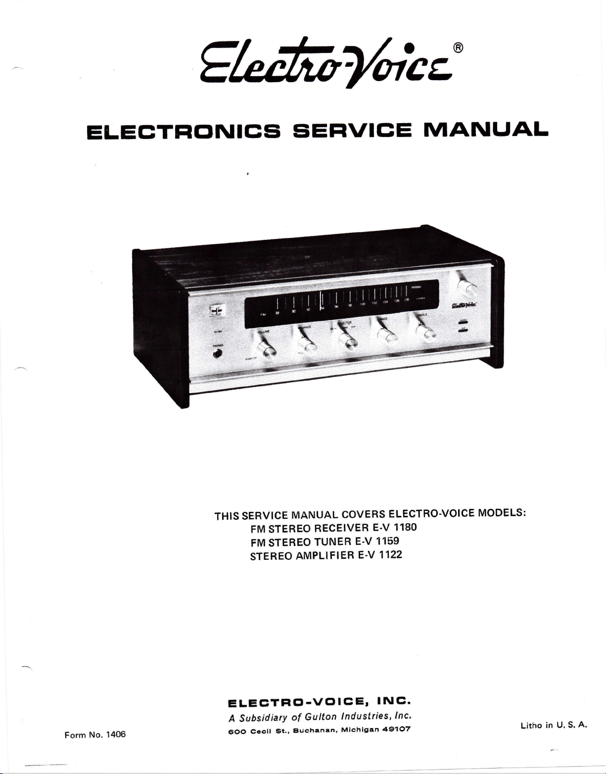
THIS SERVICE
FM STEREO
FM STEREO
STEREO
MANUAL
BECEIVER
TUNER
AMPLIFIER
ELEETFICl-VCllCEr
Gulton
A Subsidiary
ccclt
5OO
of
Buchanan,
St.,
COVERS
E-V
1159
E-V
1122
E-V
INE'
1ndLt517iss,
Mlchigan
ELECTRO.VOICE
1180
lnc'
49107
MODELS:
Litho
in u. s.
A,
INTRODUCTION
tt has
'youi
manual
been
manner.
problems
additional
need
service
This
*inO.
over-simplification.
it*p-Uv-tt"p
'of
all
*uv
vou-
SPECIFICATIONS
AMPLIFIER
(E-V
Output,
Power
IHF
Continuous
FrequeucY
and
Hum
---l
rxitiary
Magnetic
Channel
Power:
Musie
Sine
ResPonse:
Noise.
tnprt'
Phono
Separation:
lnnuts:
SensitivitY,
lnimt
Phono:
er-li-v
nu*
Controls
l18o):
irzzi,
iE-v
(rotarY)'
Volume
Balance
Selector
Bass
Treble
Outputs,
Speakers
Recorder
TaPe
Siereo
A*iop"on"t
5i*iio
was designed
as
kept
procedures are
All
Althaugh
questions,
and
guidance' Address
&E-V
1180
Wave:
lnput:
Total
Tstai
technician
the
with
possible without
as
brief
presented in a clear
tried
have
we
in special
to anticipate
instances
anv
SECTION
11221
30
watts
l0
11.5
d8,20-20,000
Better
Betrer
Mag
with
cllannel
Per
rated
dB
65
than
rated
dB below
50
than
rated
i,000
at
dB
40
Pirono-AuxiliarY
onloff
witu
P-uil/mono
Phono-Tuner-Auxiliary
4-16
of 22-dB
dB
22
of
ohms
on
at
Per
front
variation
variation
such
watts
into
8 oltms
Hz
outPut
below
output
output
4 mv
250
loo
switch
switch
50 Hz
at
kHz
10
channel
Panel
in
at
Hz
mv
mv
Technical
our
inquiries
The
any
easity
Data
to
punched to
are
sheets
production changes
added.
as uP'to'date
This
tE-v
Sensitivity:
Fruooun"u
-
'-a-----r
Hum
Tumng
Tuning
Drift:
Harmonic
Capture
Channel
SCA
Audio
StereolMono
Stereo'Indicator:
Antenna
Power
Dimensions,
Response:
Noise:
and
Range:
Indicator:
Distortion:
Ratio;
Separation:
Rejection:
Output
Input:
Requirements:
1180:
E-V
1159:
E-V
1122:
E-V
tti*it
(E'V 1159):
Switching:
Department'
fit
three-ring
a
additional
your
SECTION
E'V
specs.
Better
modulation
will
as
Possible.
TUNER
11S0&
IHF
of
Service
and
keep
at |AA%modulation
-
A11
Panel
of stereo
Tern:inals
GENERAL
110-120
binder
service
Electro-Voice
1159)
tl
d8,30-15,000
response
Actual
exceed
dBbeiow
55
than
for full
to 108
88
Zero center
Lessthan.A2%
than
Less
22
volt
.5
and
electronic
light
bloadcast
for 300
5"
and
indicates
Pull/nlono
ohm
volts. 50-60
157+"
h.,
4/a" 1t.,157+"
1t..157r"
41h"
so that
tips can
Service
uv,I$f
3
Hz
greatly
{igure.)
this
100%
quieting
megahertz
meter
l0O7o
17o at
modulation
2.s
kHz
I
dB at
40 dB
channel
Pet
quieting
full
automatic
presence^
regardless
switch
aotenna
FM
Hz AC
w" 8%"
w..$Yz"
w.,8%"
be
dB
of
d'
d.
d'
SERVICING
EOUIPMENT
TEST
FM signal
1.
kHz.
FM
2.
caiiuiaieo
Audio
3.
4. DCVTVM
Oscilloscope
5.
Harmonic
6.
STANDARD
2
generator,
Attenuator
Multiplex
nr
VTVM
Distortion
generator
livel
POWER
HARIVIONIC
(E-V
TEST
accurate
and
1'..22&
CONDITIONS:
PROCEDURE
i;v'
modulated
equivalent
or
88-108.MHz
tuning
'AnalYzer
to
down
(98
MHZ
modulation)'
OUTPUT
DISTORTION
E'V
1
.cirrier
AND
1180)
+
with
75
CONTROLS
TONE
BALANCE
SELECTOR
INPUT
SPEAKER
Terminate
1,
"
lnJr"iG
Simultaneously
2.
I".aiiei with
I""rirtulv
Connect
3.
input
1000
,Apply
4.
Ublurrnglontrol
wattsl.
TOTAL
5.
less.
E-V
The
"pu-"iiicationt
, .
LOAD
both
load
calibrated
lowdistortion
a
iacfs.
Hz'
AC
HARMONIC
and
1122
siren
amplifier
resistors,
perform the
resistor,
load
each
audio
generator output
Set
power
to
cloikwise
DISIORTION
1190
E'V
{ront
the
at
output,channels
minimum
watt
12
tollowing
conneit
and
VTVM
generator-to
audio
level
receiver
the
full
for
m?y.
!e
manuai'
this
of
tor both
the
H'D'
a
to
and
power
should
checked
CENTEHED
.,..AUX
oHMS
. .8
.
8-ohrn
into
rating'
channels'
leads
input
analvzer'
the
mV+
25O
carefullv
I
output
measure'l'37o
the
to
FLAT
non'
of an
"AUX"
1 dB @
advance
(10
volts
additional
ln
or
FM.MULTIPLEX
ALIGNMENT
permanent
1. Defeat
2. Tune
3.
4. Connect
5, Connect
6.
7. Adjust the
8. Adjust
9.
10. Tune
1
1
,
12.
the
on the l.F.
input.
assembly
Adiust with
Adjust the top slug
tuner-meter
generator
kHz deviation.
output or E-V
Tune
meter reading, NOTE;
alignment,
good
sensitivity
maximum output.
l.F.
in
well-balancd signal
Adiust
maiimum output,
the antenna,
tuning unit
setting at
Repeat steps 9 &
Remove AFC
pcb
receiver to the low
the
Adjust
with
FM
at 90
an audio
in the
additional signal
output
is improved.
bottom
the lop,
pcb
asserirbly
FM
tuning
the antenna
the signal
106 MHz.
MULTIPLEX
perlorm
and
Check
alignment
will
make
FM
ALIGNMENT
(E-V
1159
&
AFC action
a$sembly.
the AGC
respect
100 kSapot
reading
signal
1 180 tape
signal
level.
then
unit)
generator
interstage
for
ground!
"FM
proper
voltage at
to chassis
(1).
ratio
of
noise.
on
generator
MHz,3
W
VTVM and oscilloscope
output.
generator
lf
Signal
of the
slug
bottorn
ineluding slugs of
for
maximum
on oscilloscope.
coil T1
pointer
Dial
and
and
maximum
proper
for
1 0
Alignment"
MPX
E-V 1180)
grounding
by
end
FM
of
point
ground,
detector
the
to
antenna
R.F.40O Hz modulation
receiver at
on
the unit
level may be
level may be
ratio detector
of l.F.
slugs
transform€r
output consistent
in the
should
FM tuner
oscillator TR
output.
Dial
tracking and
with
band
"A"
+10.5
for
transformer
terminals. Set
the
to
MHz
90
is
completely
required to obtain a
reduced as
transformer
transformers
FM tuning unit
be setting at 9O
to 106
trimmers
pointer
best
MHz. Adiust
ALIGNMENT
necessary. lmproper
if
alignment
impossible.
point
no signal
l.F'
on
volts
for center
E-V
for
out
receiver
on the
(located
T2
with
in the FM
should
results.
"D"
pcb
DC.
t75
159
1
center
for
for
MHz.
FM
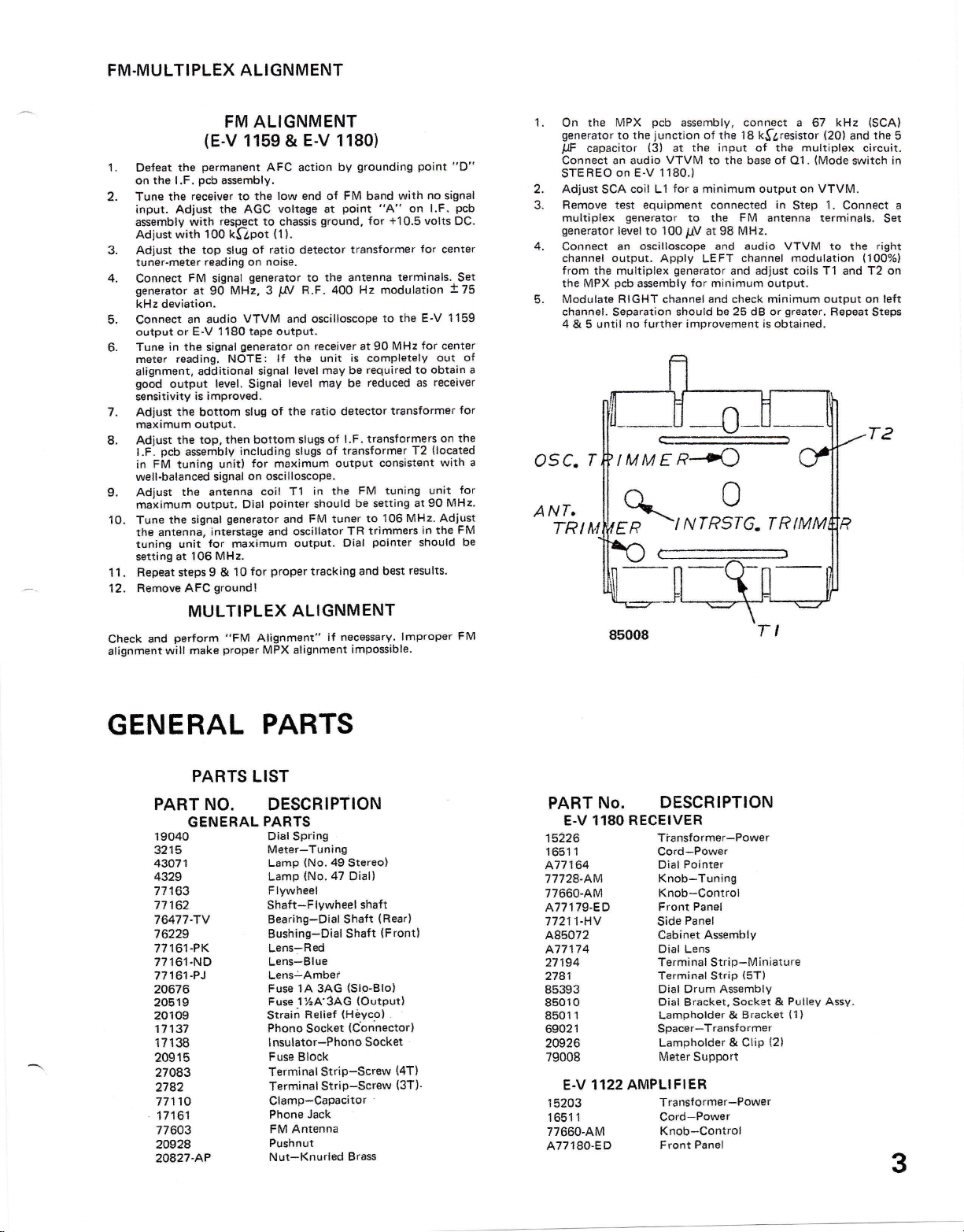
1.
the
On
generator
capacitor {3}
llF
Connect
STEREO
2. Adjust SCA coil L1
Bemove test equipment
3.
multiplex
generator
4. Connect
channel
from
the multiplex
the MPX
Modulate RIGHT
5.
channel.
4
until
& 5
pcb
MPX
to thejunction of the 18 k$l,resistor
an audio
on E-V 1180.)
g€nerator
level to 100 pV at 98 MHa.
an
output. Apply
pcb
Separation
no further improvement is
assembly,
at the
VTVM
for
a
to
oscilloscope
generator
asemb{y
for
channel
should be 25
connect a 67
input
of ths
to the base of
minimum output on VTVM.
connected
FM
the
and audio
channel
LEFT
and adjust coils
minimum output.
and
che6k minimum
Ql .
in
Step
antenna terminals,
VTVM
modulation
greater,
dB
or
obtained.
kHz
(20)
multiplex
(Mode
1,
Connect a
to the
T1
and T2 on
output
Repeat
{SCA}
and the
eircuit.
switch
right
(1007o1
on left
Steps
5
in
Set
of
L-
T
a
05C.
ANT,
be
TRllvt
IMME,?4
q_0
-i lYfRSf
ER
8soo8
G.
T I
TRTMM
GENERAL
PARTS
PARTS
LIST
PART NO. DESCRIPTION
GENERAL
lgorto
3215
43071
4329
77163
17 162
76477-TV
76229
77161-PK
77161.ND
77161-PJ
20676
20519
2010s
1713?
171 38
20915
27083
2182
77110
11161
776p3
2A928
2A827-AP
PARTS
Dial Spring
Meter-Tuning
Lamp
Lamp
Flywheel
Shaft*Flywheel
Bearihg-Dial
Bushing-Dial
Lens-Red
Lens*Blue
Lensi-Ambef
Fuse 1A 3AG {Slo-Blo}
Fuse 1Y.A
Strairi
Phono
lnsulator-Phono Sock€t
Fuse
Terminal
Terminal
(No.
49
Stereo)
(No.
47
Oiall
shaft
Shaft
Shafi
3AG {Output}
(Hiyeo)
Retief
(Cbnnector)
Socket
Block
Strip-Screw
Strip-Screw
Clamp-Capacitor
Jack
Phone
FM Antenna
Pushnut
Nut-Knurled Brass
(Rear)
{Front}
(4Tl
(3T)-
PART
No. DESCRIPTION
E.V 118O RECEIVER
15226
1651 1
A77164
77724.AM
77660-AM
A7717g-ED
77211-HV
A850]2
A77 17 4
2-1184
2781
85393
85010
8501 1
69021
20926
79008
E.V 1122 AMPLIFIER
1
5203
1
1651
77660-AM
A77180-ED
Tiansformer-Power
Cord-Power
Pointer
Dial
Knob-Tuning
Knob-Control
Panel
Front
Panel
Side
Assembly
Cabinet
Dial Lens
Terminal
Terminal Strip {5T)
Dial
Dial
Lampholder &
Spacer-Transformer
Lampholder
Meter Support
Transf ormer-Power
Cord-Power
Strip-Miniature
Drum Assembly
Eracket.
Socket &
Brackat
& Clip
Knob-Control
Front Panel
{2}
Pulley
(1
l
Assy.
3
PART NO.
DESCRIPTION
PART
No.
DESCRIPTION
77212-HU
A85073
27050
27036
77178
zGrr9
E.V 1159
15211
A17241
16/.12
77210-AM
7727o-AM
A77?34-ED
85r01
77212-HV
Panel
Side
Assy.
Cabinet
Terminal Strip
Terminal
I nsulator-Fishpaper
Lampholder
Strip
TUNER
Transformer-Powgr
Pointer
Dial
AC Line Cord
Knob
Tuning
-
Knob
Selector
-
Front Panel
Cabinet AssBmbly
Panel
Side
t3Tl
(5T)
(81t"1
A77235
20889
20s33
56089
27050
20797
85132
20920
77265
PACKING PARTS
96755
96754
533400
633644
53sSX)
Dial
Lens
Fuse
1/10A
Lampholder
Switch-Power
Terminal
Strain Relief
Dlal
Dial Drum
Spacer-Panel
carton
Carton
lnstruction
lnsruction
lnstruction
Strip
Bracket,
Assy.
(E-v
(E-V
Sheet
She6t
Sheet
(Slo-Blo)
Socket
(3T)
(Heyco)
Socket
1180)
1 159
&
{E-V
(E-V
(E"V
Pulley
&
E.V r
118O}
1159)
1 1221
Assy.
1221
4
2300MF
2500
ilF
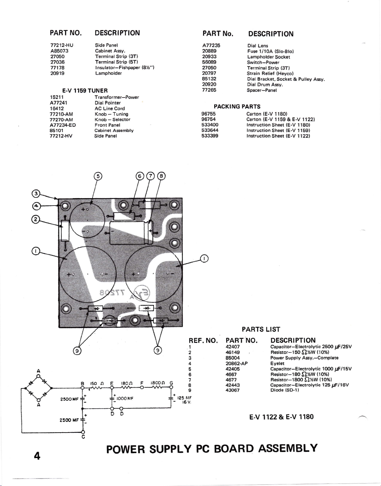
POWER
J
4
5
6
7
8
s
+
I25 ttlF
-
16V,
SUPPLY
PC
BOARD
PART
42447
48149
85004
20862-AP
424oE
4657
&77
42443
43067
PARTS
NO.
LIST
DESCBIPTION
Gapacitor-E
Besistor-t50
Power
Eyalet
Capcitor-El€clrolytic
Resistor-l80
Resistor*18@
Capacitor-Electrolytic
Diode
1122&
Ery
ASSEMBLY
lectrolytic 26ff)
O:aw
Assy.-Complste
Supply
$ll(w
(SD-1)
1180
E-V
O}.w
{lox}
1fi)O
t o%l
{
{tox,
125
ltrlz6v
rf
16V
I
tfr
5V
/1
 Loading...