

Page 1
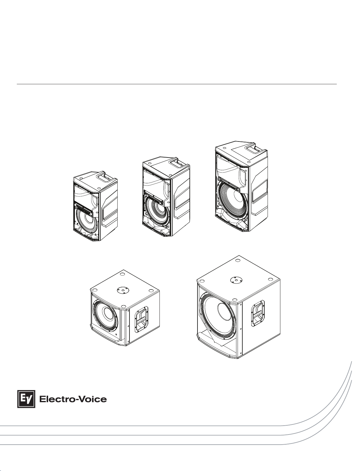
ELX200 Passive Loudspeakers
ELX200-10 | ELX200-12 | ELX200-15 | ELX200-12S | ELX200-18S
en | Installation manual
Page 2

Page 3

Table of contents
en 3
1
1.1 Important safety instructions 4
1.2 Suspension 4
1.3 Precautions 5
1.4 Notices 5
2
2.1 System features 6
3
3.1 Tripod or pole mount 8
3.2 Floor monitor 10
4
5
5.1 Basic stereo system using full-range systems 14
5.2 Using full-range systems as stage monitors 15
5.3 Stacking full-range systems with subwoofers 16
6
7
7.1 Dimensions 20
7.2 Frequency response 21
Safety 4
Description 6
Tripod and floor monitor operation 8
Suspension 11
Recommended configurations 14
Troubleshooting 18
Technical data 19
Electro-Voice Installation manual 2017.10 | 01 | F.01U.326.890
Page 4

!
!
ELX200 Passive Loudspeakers
1
1.1
1.2
Safety
Important safety instructions
1. Read these instructions.
2. Keep these instructions.
3. Heed all warnings.
4. Follow all instructions.
5. Clean only with a dry cloth.
6. Do not install near any heat sources such as radiators, heat registers, stoves, or other
apparatus (including amplifiers) that produce heat.
7. Only use attachments/accessories specified by the manufacturer.
8. Use only with the cart, stand, tripod, bracket, or table specified by the manufacturer, or
with the apparatus. When a cart is used, use caution when moving the cart/apparatus
combination to avoid injury from tip-over.
Suspension
Warning!
Suspending any object is potentially dangerous and should only be attempted by individuals
who have a thorough knowledge of the techniques and regulations of suspending objects
overhead. Electro-Voice strongly recommends all loudspeakers be suspended taking into
account all current national, federal, state, and local laws and regulations. It is the
responsibility of the installer to ensure all loudspeakers are safely installed in accordance
with all such requirements. When loudspeakers are suspended, Electro-Voice strongly
recommends the system be inspected at least once per year or as laws and regulations
require. If any sign of weakness or damage is detected, remedial action should be taken
immediately. The user is responsible for making sure the wall, ceiling, or structure is capable
of supporting all objects suspended overhead. Any hardware used to suspend a loudspeaker
not associated with Electro-Voice is the responsibility of others.
Warning!
Do not suspend this product in any other manner than explicitly described in this manual, or
Electro-Voice installation guides. Do NOT use handles to suspend the loudspeaker. Handles
on Electro-Voice loudspeakers are intended to only be used for temporary transport by
people. Items, such as fiber rope, wire rope, cables, or other types of materials cannot be
used to suspend loudspeaker from the handles.
2017.10 | 01 | F.01U.326.890 Installation manual Electro-Voice
Page 5
!
!
!
en 5
1.3
1.4
Precautions
Do not use Electro-Voice loudspeakers in an environment where temperatures
are below 0°C (32°F) or exceed +40°C (104°F).
Never expose an Electro-Voice loudspeaker to rain, water, or high moisture.
Electro-Voice loudspeakers are easily capable of generating sound pressure
levels sufficient to cause permanent hearing damage to anyone within normal
coverage distance. Caution should be taken to avoid prolonged exposure to
sound pressure levels exceeding 90 dB.
Notices
Old electrical and electronic appliances
Electrical or electronic devices that are no longer serviceable must be collected separately and
sent for environmentally compatible recycling (in accordance with the European Waste
Electrical and Electronic Equipment Directive).
To dispose of old electrical or electronic devices, you should use the return and collection
systems put in place in the country concerned.
Copyright and disclaimer
All rights reserved. No part of this document may be reproduced or transmitted in any form by
any means, electronic, mechanical, photocopying, recording, or otherwise, without the prior
written permission of the publisher. For information on getting permission for reprints and
excerpts, contact Electro-Voice.
The content and illustrations are subject to change without prior notice.
Electro-Voice Installation manual 2017.10 | 01 | F.01U.326.890
Page 6

ELX200 Passive Loudspeakers
2
Description
Thank you for choosing an Electro-Voice passive loudspeaker system. Please take time to
consult the manual to understand all the features built into your EV system and fully utilize its
performance capabilities.
ROCK SOLID SOUND: Electro-Voice ELX200 portable loudspeakers
The ELX200 series is the newest member of the best-selling Electro-Voice portable
loudspeaker family. Positioned above ZLX and below the EKX series, the ELX200 series
features ten models (five powered and five passive), including 10-inch, 12-inch and 15-inch
two-way models, and 12-inch and 18-inch subwoofers.
The ELX200 series is designed to deliver an unprecedented combination of sound quality,
portability and durability at its price point. All-new custom components—tested to levels far
exceeding the industry norm—make ELX200 a robust workhorse capable of handling real-world
abuse and professional applications beyond the capability of competitors’ products in its
category.
Every aspect of ELX200 is designed for ideal results as part of the whole - the acoustical,
electrical and mechanical components all work together seamlessly. The full-range models
feature a low profile form factor designed with a high-spec composite enclosure to balance
weight, manageability, as well as structural integrity. The subwoofers pack powerful lowfrequency output into a surprisingly compact footprint, and feature tuned 15 mm thick wood
enclosures with a premium top-coat finish. The proprietary features that have made the other
members of the EV portable speaker family a go-to for best-in-class performance are also
present: Signal Synchronized Transducers (SST) waveguide concept.
EV's industry-leading quality and testing procedures yield efficient transducer design and
meaningful specs, resulting in components that deliver accurate, linear response at the
system’s highest output levels. Translation: loud and clear all the way up to the limit. Unified in
one of the strongest full-range composite enclosures ever built by EV. The ELX200 is
established as the new benchmark for toughness - both acoustically and physically; maximum
efficiency with maximum toughness.
2.1
2017.10 | 01 | F.01U.326.890 Installation manual Electro-Voice
System features
ELX200-10 — 10" two-way passive loudspeaker system
▪ 1200 W (Peak), 127 dB peak SPL system that is reliability verified with over 500 hours of
abuse testing and endurance testing to 4x typical industry practices.
▪ 1.4 inch DH-1C (1 inch exit) titanium compression driver for extended transparent high-
frequency response.
▪ High-output EVS-10M woofer designed to exacting specifications for superior durability
and exceptional low-frequency reproduction.
▪ EV-patented Signal Synchronized Transducers (SST) waveguide design provides precise
and consistent coverage, minimal distortion, and maximized acoustical loading.
▪ Professional-grade hardware: three M10 threaded mounting points for forged eyebolts,
integrated pole-mounts and the proven ZLX two-handle design for easy lifting.
Page 7

en 7
ELX200-12 — 12" two-way passive loudspeaker system
▪ 1200 W (peak), 128 dB peak SPL system that is reliability verified with over 500 hours of
abuse testing and endurance testing to 4x typical industry practices.
▪ 1.4 inch DH-1C (1 inch exit) titanium compression driver for extended transparent high-
frequency response.
▪ High-output EVS-12M woofer designed to exacting specifications for superior durability
and exceptional low-frequency reproduction.
▪ EV-patented Signal Synchronized Transducers (SST) waveguide design provides precise
and consistent coverage, minimal distortion, and maximized acoustical loading.
▪ Professional-grade hardware: three M10 threaded mounting points for forged eyebolts,
integrated pole-mounts and the proven ZLX three-handle design for easy lifting.
ELX200-15 — 15" two-way passive loudspeaker system
▪ 1200 W (peak), 130 dB peak SPL system that is reliability verified with over 500 hours of
abuse testing and endurance testing to 4x typical industry practices.
▪ 1.4 inch DH-1C (1 inch exit) titanium compression driver for extended transparent high-
frequency response.
▪ High-output EVS-15M woofer designed to exacting specifications for superior durability
and exceptional low-frequency reproduction.
▪ EV-patented Signal Synchronized Transducers (SST) waveguide design provides precise
and consistent coverage, minimal distortion, and maximized acoustical loading.
▪ Professional-grade hardware: three M10 threaded mounting points for forged eyebolts,
integrated pole-mounts and the proven ZLX three-handle design for easy lifting.
ELX200-12S — 12" passive subwoofer system
▪ 1600 W (peak), 129 dB peak SPL utilizing high-sensitivity transducer designed and
engineered by EV for maximum punch.
▪ High-output EVS-12L woofer designed to exacting specifications for superior durability
and exceptional low-frequency reproduction.
▪ System reliability verified with over 500 hours of abuse testing and endurance testing.
▪ Ideal for portable and installed applications. Lightweight, compact 15 mm wood
enclosure with internal bracing with durable polyurea top-coat finish.
▪ Professional-grade hardware: integrated M20 threaded pole mount plate and two-handle
design for easy lifting.
ELX200-18S — 18" passive subwoofer system
▪ 1600 W (peak), 133 dB peak SPL utilizing high-sensitivity transducer designed and
engineered by EV for maximum punch.
▪ High-output EVS-18L woofer designed to exacting specifications for superior durability
and exceptional low-frequency reproduction.
▪ System reliability verified with over 500 hours of abuse testing and endurance testing.
▪ Ideal for portable and installed applications. Lightweight, compact 15 mm wood
enclosure with internal bracing with durable polyurea top-coat finish.
▪ Professional-grade hardware: integrated M20 threaded pole mount plate and two-handle
design for easy lifting.
Electro-Voice Installation manual 2017.10 | 01 | F.01U.326.890
Page 8
!
!
A
ELX200 Passive Loudspeakers
3
3.1
Tripod and floor monitor operation
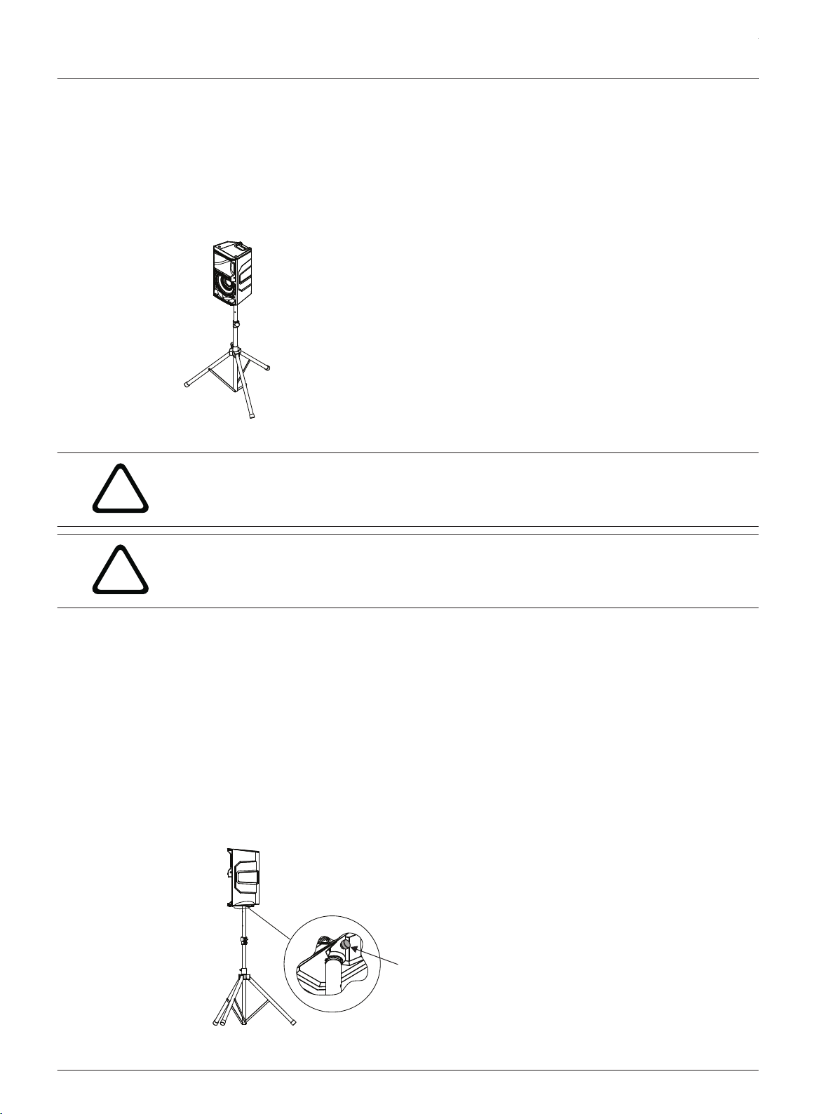
Tripod or pole mount
ELX200-10, ELX200-12, and ELX200-15 loudspeakers mount on a tripod stand or on a pole
above a subwoofer.
Mounting a loudspeaker on a tripod stand
Figure 3.1: Full-Range models on a tripod stand
Caution!
Tripod is not evaluated for safety with this loudspeaker. Check the specifications of the tripod
stand to be certain it is capable of supporting the weight of the loudspeaker.
Caution!
Two person lift and placement is recommended for the heavier loudspeakers. Single person
lift and placement of heavier loudspeakers could cause injury.
To mount a loudspeaker on a tripod stand, do the following:
1. Place the tripod stand on a level and stable surface.
▪ Fully extend the legs on the tripod stand.
▪ Do not compromise the tripod stands structural integrity by trying to make the stand
taller.
▪ Do not attempt to suspend more than one loudspeaker on a stand designed for a single
loudspeaker.
2. Using two hands lift the loudspeaker.
3. Set the pole cup located on the bottom of the loudspeaker onto the pole.
4. Tighten the thumb screw (A) to secure the loudspeaker to the pole.
The thumb screw is only available on the 12" and 15" full-range loudspeaker models. The 10"
full-range loudspeaker does not have a thumb screw.
2017.10 | 01 | F.01U.326.890 Installation manual Electro-Voice
Page 9

!
en 9
Mounting a loudspeaker on a pole
Caution!
Two person lift and placement is recommended for the heavier loudspeakers. Single person
lift and placement of heavier loudspeakers could cause injury.
To mount a loudspeaker on a pole, do the following:
1. Place the subwoofer on a level and stable surface.
2. Insert the M20 threaded pole into the combo pole cup on the top of the subwoofer.
3. Turn the M20 threaded pole clockwise to secure the pole to the subwoofer.
4. Using two hands lift the loudspeaker.
5. Set the pole cup located on the bottom of the loudspeaker onto the pole.
6. Tighten the thumb screw to secure the loudspeaker to the pole.
The thumb screw is only available on the 12" and 15" full-range loudspeaker models. The 10"
full-range loudspeaker does not have a thumb screw.
Electro-Voice Installation manual 2017.10 | 01 | F.01U.326.890
Page 10

90°
50°
60°
OPTIMAL
COVERAGE
OPTIMAL
COVERAGE
ELX200 Passive Loudspeakers
3.2
Floor monitor
ELX200-10, ELX200-12, and ELX200-15 loudspeakers may be used as a floor monitor by
placing the loudspeaker on the integral monitor angle.
To set up a loudspeaker as a floor monitor, do the following:
1. Place the loudspeaker on a level and stable surface.
2. Safely route cables to prevent injury to performers, production crew, and audience
members.
Notice!
Secure cables with wire ties or tape whenever possible.
Figure 3.2: Optimum coverage in monitor position (side view left and front view right)
2017.10 | 01 | F.01U.326.890 Installation manual Electro-Voice
Page 11

!
A
B
en 11
4
Suspension
The ELX200 enclosures have three M10 threaded points; two points on top of the enclosure
and one point on the bottom. Forged shoulder eyebolts rated for overhead suspension may be
used to suspend an individual loudspeaker, such as the EBK1-M10-3PACK accessory.
Warning!
Suspending any object is potentially dangerous and should only be attempted by individuals
who have a thorough knowledge of the techniques and regulations of suspending objects
overhead. Electro-Voice strongly recommends all loudspeakers be suspended taking into
account all current national, federal, state, and local laws and regulations. It is the
responsibility of the installer to ensure all loudspeakers are safely installed in accordance
with all such requirements. When loudspeakers are suspended, Electro-Voice strongly
recommends the system be inspected at least once per year or as laws and regulations
require. If any sign of weakness or damage is detected, remedial action should be taken
immediately. The user is responsible for making sure the wall, ceiling, or structure is capable
of supporting all objects suspended overhead. Any hardware used to suspend a loudspeaker
not associated with Electro-Voice is the responsibility of others.
Figure 4.1: Suspension points (A top, B bottom)
Prior to use, inspect the suspension points and associated hardware for any cracks,
deformations, broken welds, corrosion, missing or damaged components which could reduce
the suspension points strength. Replace any damaged hardware. Never exceed the limitations
or maximum recommended load intended for the suspension points. As an added safety
measure, it is suggested the user install an extra suspension point back to the building
structural supports. This redundant safety point should have as little slack as possible (less
than one inch is preferable). Prior to each use, inspect the loudspeaker enclosures for any
cracks, deformations, missing or damaged components, which could reduce enclosure
strength. Replace any loudspeaker systems that are damaged or missing hardware.
Electro-Voice Installation manual 2017.10 | 01 | F.01U.326.890
Page 12

!
B
A
ELX200 Passive Loudspeakers
Installing the eyebolts
To install the eyebolts, do the following:
1. Remove the three fly point covers from the suspension points.
2. Install M10 eyebolts and washers into the suspension points.
Warning!
Eyebolts must be fully seated and oriented in the plane of pull. Always use washers under the
eyebolt to distribute the load on the enclosure.
Figure 4.2: Eyebolt shown with washers (A) and without washers (B)
2017.10 | 01 | F.01U.326.890 Installation manual Electro-Voice
Page 13

!
5° MAX
5° MAX
5° MAX
5° MAX
90°
10°
90°
!
Figure 4.3: Eyebolts shown orientated in the plane of pull (left correct, right incorrect)
en 13
Warning!
Never exceed the limitations or maximum recommended working load for Electro-Voice
loudspeakers.
Disregarding this warning could result in serious injury or death.
Figure 4.4: Maximum working load - vertical orientation 50 lb per suspension point
Warning!
Never suspend ELX200 Series loudspeakers in a vertical column array.
Disregarding this warning could result in serious injury or death.
Figure 4.5: Loudspeaker vertical suspension (Correct, left; Incorrect, right)
Electro-Voice Installation manual 2017.10 | 01 | F.01U.326.890
Page 14

Input A
Input B
Mixer
Amplifier
Output 1
Output 2
ELX200-10,
ELX200-12,
or
ELX200-15
!
ELX200 Passive Loudspeakers
5
5.1
Recommended configurations
Basic stereo system using full-range systems
Basic stereo system using ELX200-10, ELX200-12 or ELX200-15 loudspeakers (ELX200-15
versions shown).
NL4 Pin Configuration
Pin 1+ and 1- Used
Pin 2+ and 2- Not used
Caution!
Do not exceed the maximum load rating of the amplifier.
# of Speakers Nominal Minimum
1 8 Ohms 7.2 Ohms
2 4 Ohms 3.6 Ohms
3 2.7 Ohms 2.4 Ohms
4 2 Ohms 1.8 Ohms
Amplifier Load (per Output Channel)
2017.10 | 01 | F.01U.326.890 Installation manual Electro-Voice
Page 15

Amplifier
Mixer
Output 1
Output 2
Input B
Input A
!
en 15
5.2
Using full-range systems as stage monitors
Multiple ELX200-10, ELX200-12 or ELX200-15 loudspeakers in monitor position (ELX200-15
versions shown).
NL4 Pin Configuration
Pin 1+ and 1- Used
Pin 2+ and 2- Not used
Caution!
Do not exceed the maximum load rating of the amplifier.
Amplifier Load (per Output Channel)
# of Speakers Nominal Minimum
1 8 Ohms 7.2 Ohms
2 4 Ohms 3.6 Ohms
3 2.7 Ohms 2.4 Ohms
4 2 Ohms 1.8 Ohms
Electro-Voice Installation manual 2017.10 | 01 | F.01U.326.890
Page 16

Mixer
Output 2
Input A
Input B
Output 1
ELX200-10,
ELX200-12,
or
ELX200-15
ELX200-12S
or
ELX200-18S
Amplifier
!
ELX200 Passive Loudspeakers
5.3
Stacking full-range systems with subwoofers
This configuration allows a user to increase the low frequency performance without using
additional amplifier channels (ELX200-15 and ELX200-18S versions shown).
NL4 Pin Configuration
Pin 1+ and 1- Used
Pin 2+ and 2- Not used
Caution!
Do not exceed the maximum load rating of the amplifier.
2017.10 | 01 | F.01U.326.890 Installation manual Electro-Voice
Page 17

en 17
Amplifier Load (per Output Channel)
# of Subwoofer/Full-Range
Combinations
1 4 Ohms 3.8 Ohms
2 2 Ohms 1.9 Ohms
Nominal Minimum
Electro-Voice Installation manual 2017.10 | 01 | F.01U.326.890
Page 18

ELX200 Passive Loudspeakers
6
Problem Possible Cause(s) Action
1. No sound Amplifier Connect a known working test loudspeaker to the
2. Poor
Low-Frequency
Response
Troubleshooting
amplifier outputs. If there is no sound, verify all the
electronics are on, the signal routing is correct, the
source is active; the volume is turned up, etc.
Correct/repair/replace as necessary. If there is sound,
the problem is in the wiring.
Wiring Verify you have connected the correct cables to the
amplifier. Play something at a low level through the
amplifier. Connect the test loudspeaker in parallel with
the malfunctioning line. If the sound level is gone or is
very weak, the line has a short in it (possibly a severe
scrape, pinch, or a missed connection). Using the test
loudspeaker, move down the line and test each
connection/junction until you find the problem and
correct it. Observe proper polarity.
Loudspeakers wired
out-of-polarity
When two loudspeakers are connected out of polarity,
the low frequencies will cancel each other acoustically.
Carefully observe the wire markings or tracers on your
loudspeaker wires. Verify the amplifier (+) terminal is
connected to pin 1+ of the NL4 connector and the
amplifier (-) terminal is connected to pin 1-of the NL4
connector.
3. Intermittent output
such as cracking or
distortion
4. Constant noise
such as buzzing,
hissing or humming
If these suggestions do not solve your problem, contact your nearest Electro-Voice dealer or
Electro-Voice distributor.
Faulty connection Check all connections at amplifier and loudspeakers to
ensure they are all clean and tight. If the problem
persists, check the wiring. See problem 1.
Defective source or
other electronic
device
Poor system
grounding or ground
loop
If noise is present, but no program material is playing,
evaluate each component as necessary to isolate the
problem. Most likely there is a break in the signal path.
Check and correct the system grounding, as required.
2017.10 | 01 | F.01U.326.890 Installation manual Electro-Voice
Page 19

en 19
7
Technical data
ELX200-10, ELX200-12, and ELX200-15
ELX200-10 ELX200-12 ELX200-15
Freq. response (-3 dB): 65 Hz - 20 kHz
Freq. range (-10 dB): 49 Hz - 22 kHz
Axial sensitivity: 90 dB
Maximum SPL: 127 dB
Recommended high-pass
1
1,2
55 Hz 50 Hz 42 Hz
1
1
77 Hz - 17 kHz
51 Hz - 20 kHz
1
93 dB
128 dB
1,2
1
1
77 Hz - 16 kHz
52 Hz - 19 kHz
1
95 dB
130 dB
1,2
freq.:
Coverage (H x V): 90˚x 60˚
Power handling: 300 W Continuous, 1200 W Peak
LF transducer: EVS-10M 254 mm
(10 in)
EVS-12M 300 mm
(12 in)
EVS-15M 381 mm
(15 in)
HF transducer: DH-1C 1-inch titanium compression driver
Crossover freq.: 2 kHz 1.7 kHz 1.6 kHz
Nominal impedance: 8 Ω
1
1
Minimum impedance: 7.2 Ω 7.5 Ω 7.0 Ω
Connectors: Dual NL4
Suspension: (3) M10 suspension points
Dimensions (H x W x D):
Net weight: 13.4 kg (29.6 lb) 15.2 kg (33.4 lb) 18.7 kg (41.2 lb)
Shipping weight: 15.3 kg (33.7 lb) 17.1 kg (37.7 lb) 21.4 kg (47.2 lb)
Enclosure: Polypropylene
Grille: 18 AWG steel with powdercoat
Color: Black
531 x 330 x 319
mm (in)
1
Full-space measurement.
2
Maximum SPL is measured at 1 m using broadband pink noise at rated peak power rating.
(21.0 x 13.0 x 12.6)
629 x 363 x 344
(24.8 x 14.3 x 13.6)
710 x 423 x 384
(28.0 x 16.6 x 15.1)
Electro-Voice Installation manual 2017.10 | 01 | F.01U.326.890
Page 20

330 mm
[13 in]
273 mm [11 in]
140 mm [6 in]
531 mm
[21 in]
226 mm [9 in]
220mm
[9 in]
319 mm [13 in]
118 mm [5 in]
363 mm
[14 in]
311 mm
[12 in]
155 mm [6 in]
629 mm
[25] in
253 mm [10 in]
256 mm
[10 in]
344 mm [14 in]
163 mm
[6 in]
ELX200 Passive Loudspeakers
ELX200-12S and ELX200-18S
ELX200-12S ELX200-18S
Freq. response (-3 dB): 42 Hz - 220 Hz
Freq. range (-10 dB): 33 Hz - 300 Hz
Axial sensitivity: 93 dB
Maximum SPL: 129 dB
1
1,2
1
1
45 Hz - 200 Hz
28 Hz - 300 Hz
1
94 dB
1,2
133 Hz
1
1
Recommended high-pass
Power handling: 400 W Continuous, 1600 W Peak
LF transducer: EVS-12L 300 mm (12 in) EVS-18L 457 mm (18 in)
Nominal Impedance: 8 Ω
Minimum impedance: 6.9 Ω 7.2 Ω
Connectors: Dual NL4
Enclosure: 15 mm plywood with durable polyurea top-coat finish
Dimensions (H x W x D):
Net weight: 17.2 kg (38.0 lb) 26.6 kg (58.7 lb)
Shipping weight: 20.2 kg (44.6 lb) 30.5 kg (67.3 lb)
42 Hz 35 Hz
freq.:
Grille: 18 AWG steel with powdercoat
Color: Black
397 x 445 x 457
mm (in)
1
Half-space measurement.
2
Maximum SPL is measured at 1 m using broadband pink noise at rated peak power rating.
16.7 x 17.6 x 18.0
600 x 507 x 574
23.7 x 20.0 x 22.6
7.1
Dimensions
Figure 7.1: ELX200-10 dimensions
Figure 7.2: ELX200-12 dimensions
2017.10 | 01 | F.01U.326.890 Installation manual Electro-Voice
Page 21

366 mm
[14.40 in]
710 mm
[27.94 in]
164 mm
6.44 in
384 mm
[15.12 in]
422 mm
[16.61 in]
445 mm
[18 in]
397 mm
[16 in]
225 mm
[9 in]
160 mm [6 in]
229 mm
[9in]
223 mm
[9 in]
457 mm [18 in]
229 mm
[9 in]
222 mm
[9 in]
507 mm
[20 in]
256 mm
[10 in]
229 mm
[9 in]
160 mm [6 in]
274 mm
[11 in]
600 mm
24 in
287 mm
[11 in]
574 mm
[23 in]
Figure 7.3: ELX200-15 dimensions
Figure 7.4: ELX200-12S dimensions
en 21
Figure 7.5: ELX200-18S dimensions
7.2
Electro-Voice Installation manual 2017.10 | 01 | F.01U.326.890
Frequency response
Figure 7.6: ELX200-10 frequency response and impedance
Page 22

ELX200 Passive Loudspeakers
Figure 7.7: ELX200-12 frequency response and impedance
Figure 7.8: ELX200-15 frequency response and impedance
Figure 7.9: ELX200-12S frequency response and impedance
2017.10 | 01 | F.01U.326.890 Installation manual Electro-Voice
Page 23

Figure 7.10: ELX200-18S frequency response and impedance
en 23
Electro-Voice Installation manual 2017.10 | 01 | F.01U.326.890
Page 24

Bosch Sicherheitssysteme GmbH
Robert-Bosch-Ring 5
85630 Grasbrunn
Germany
www.boschsecurity.com
© Bosch Sicherheitssysteme GmbH, 2017
Bosch Security Systems, Inc
12000 Portland Avenue South
Burnsville MN 55337
USA
www.electrovoice.com
 Loading...