

Electro-Voice ELX200-18SP-US, ELX200-15P-EU, ELX200-12SP-EU, ELX200-18SP-EU, ELX200-10P-AP Installation Manual
...Page 1
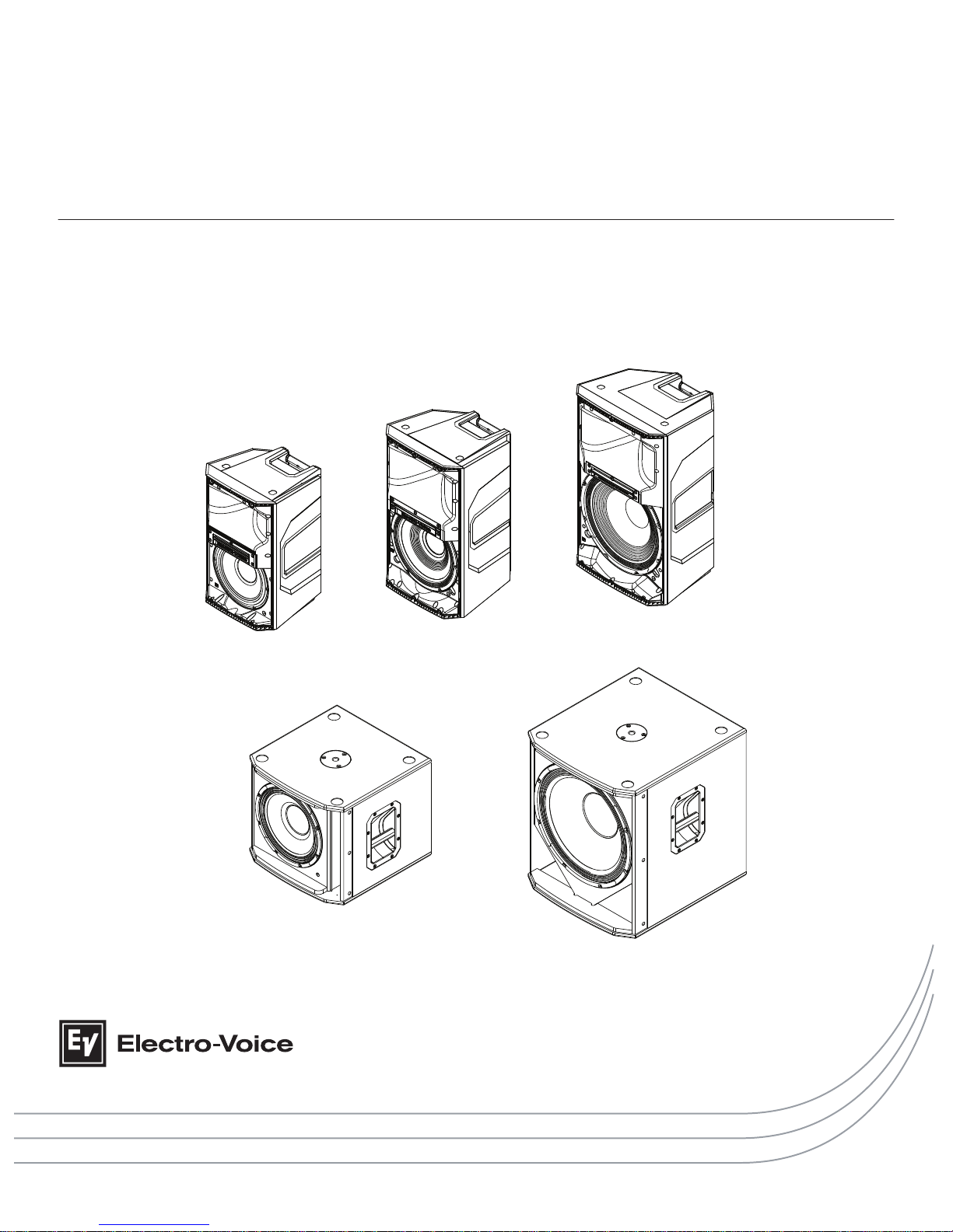
ELX200 Powered Loudspeakers
en | Installation manual
Page 2

Page 3

Table of contents
1
Safety 4
1.1 Important safety instructions 4
1.2 Suspension 5
1.3 FCC information 6
1.4 Precautions 6
1.5 Notices 7
2
Description 8
2.1 Short information 8
2.2 System features 9
2.3 Quick setup 11
3
Tripod and floor monitor operation 13
3.1 Tripod or pole mount 13
3.2 Floor monitor 15
4
Suspension 16
5
Amplifier DSP 19
5.1 Amplifier DSP controls 19
5.2 System status 21
5.3 DSP controls 22
5.3.1 Full-Range loudspeaker DSP control menu 22
5.3.2 Subwoofer DSP control menu 27
6
Pairing the QuickSmart Mobile application 32
7
Recommended configurations 33
7.1 Daisy-chaining full-range systems 33
7.2 MP3 player MONO configuration 34
7.3 MP3 player STEREO configuration 35
7.4 Using full-range systems as monitors 36
7.5 Stacking full-range systems with subwoofers 37
8
Troubleshooting 38
9
Technical data 40
9.1 Dimensions 41
9.2 Frequency Response 42
en 3
Electro-Voice Installation manual 2017.06 | 01 | F.01U.326.891
Page 4
Safety
Important safety instructions
WARNING: TO REDUCE THE RISK OF
FIRE OR ELECTRIC SHOCK, DO NOT
OVEREXPOSE THIS APPLIANCE TO RAIN
OR MOISTURE
AVIS: RISQUE DE CHOC ELECTRIQUE,
NE PAS OUVRIR.
WARNING: THE MAINS PLUG OR AC
INLET IS USED AS A DISCONNECT
DEVICE. THE DISCONNECT DEVICE
SHALL REMAIN READILY OPERABLE.
WARNING: CONNECT ONLY TO MAINS
SOCKET WITH PROTECTIVE EARTHING
CONNECTION.
WARNING: TO REDUCE THE RISK OF
ELECTRIC SHOCK, DO NOT REMOVE
COVER (OR BACK) AS THERE ARE NO
USER-SERVICABLE PARTS INSIDE.
REFER SERVICING TO QUALIFIED
PERSONNEL.
The lightening flash with arrowhead
symbol, within an equilateral triangle is
intended to alert the user to the
presence of uninsulated “dangerous
voltage” within the product’s enclosure
that may be sufficient magnitude to
constitute a risk of electric shock to
persons.
!
The exclamation point within an
equilateral triangle is intended to alert
the user to the presence of important
operating and maintenance (servicing)
instructions in the literature
accompanying the appliance.
The asterisk within an equilateral
triangle is intended to inform the user to
necessary installation or removal
instructions regarding equipment or
hardware use relating to the system.
1. Read these instructions.
2. Keep these instructions.
3.
Heed all warnings.
4. Follow all instructions.
5. Do not use this apparatus near water.
6. Clean only with a dry cloth.
7. Do not block any ventilation openings. Install in accordance with the manufacturer's
instructions.
8. Do not install near any heat sources such as radiators, heat registers, stoves, or other
apparatus (including amplifiers) that produce heat.
9. Do not defeat the safety purpose of the polarized or grounding-type plug. A polarized plug
has two blades with one wider than the other. A grounding type plug has two blades and
a third grounding prong. The wide blade or the third prong is provided for your safety. If
the provided plug does not fit into your outlet, consult an electrician for replacement of
the obsolete outlet.
10. Protect the power cord from being walked on or pinched particularly at plugs,
convenience receptacles, and the point where they exit from the apparatus.
11. Only use attachments/accessories specified by the manufacturer.
12. Use only with the cart, stand, tripod, bracket, or table specified by the manufacturer, or
with the apparatus. When a cart is used, use caution when moving the cart/apparatus
combination to avoid injury from tip-over.
13. Unplug the apparatus during lightning storms or when unused for long periods of time.
1
1.1
ELX200 Powered Loudspeakers
2017.06 | 01 | F.01U.326.891 Installation manual Electro-Voice
Page 5
14. Refer all servicing to qualified service personnel. Servicing is required when the
apparatus has been damaged in any way, such as power-supply cord or plug is damaged,
liquid has been spilled or objects have fallen into the apparatus, the apparatus has been
exposed to rain or moisture, does not operate normally, or has been dropped.
15. No naked flame sources, such as lighted candles, should be placed on the apparatus.
16.
To reduce the risk of fire or electric shock, do not expose this apparatus to rain or
moisture. The apparatus should not be exposed to dripping or splashing. Objects filled
with liquids, such as vases should not be placed on apparatus.
17. Do not block any ventilation openings. Install in accordance with the manufacturer's
instructions.
18. Minimum 60 cm (2 ft) distances around the apparatus for sufficient ventilation.
19. The ventilation should not be impeded by covering the ventilation openings with items,
such as newspapers, table-cloths, curtains, etc.
20. To completely disconnect AC power from this apparatus, the power supply cord must be
unplugged.
Suspension
!
Warning!
Suspending any object is potentially dangerous and should only be attempted by individuals
who have a thorough knowledge of the techniques and regulations of suspending objects
overhead. Electro-Voice strongly recommends all loudspeakers be suspended taking into
account all current national, federal, state, and local laws and regulations. It is the
responsibility of the installer to ensure all loudspeakers are safely installed in accordance
with all such requirements. When loudspeakers are suspended, Electro-Voice strongly
recommends the system be inspected at least once per year or as laws and regulations
require. If any sign of weakness or damage is detected, remedial action should be taken
immediately. The user is responsible for making sure the wall, ceiling, or structure is capable
of supporting all objects suspended overhead. Any hardware used to suspend a loudspeaker
not associated with Electro-Voice is the responsibility of others.
!
Warning!
Do not suspend this product in any other manner than explicitly described in this manual, or
Electro-Voice
installation guides. Do NOT use handles to suspend the loudspeaker. Handles
on Electro-Voice
loudspeakers are intended to only be used for temporary transport by
people. Items, such as fiber rope, wire rope, cables, or other types of materials cannot be
used to suspend loudspeaker from the handles.
1.2
en 5
Electro-Voice Installation manual 2017.06 | 01 | F.01U.326.891
Page 6
FCC information
IMPORTANT: Do not modify this unit! Changes or modifications not expressly approved by the
manufacturer could void the user’s authority, granted by the FCC, to operate the equipment.
Notice!
This equipment has been tested and found to comply with the limits for a Class B digital
device, pursuant to Part 15 of the FCC Rules. These limits are designed to provide reasonable
protection against harmful interference in a residential installation. This equipment generates,
uses and can radiate radio frequency energy and, if not installed and used in accordance with
the instructions, may cause harmful interference to radio communications. However, there is
no guarantee interference will not occur in a particular installation.
If this equipment does cause harmful interference to radio or television reception or receive
audible interference from radio, television or communications equipment, which can be
determined by turning the equipment off and on. The user is encouraged to try to correct the
interference by one or more of the following measures:
▪ Reorient or relocate the receiving antenna.
▪ Increase the separation between the equipment and receiver.
▪ Connect the equipment into an outlet on a circuit different from that to which the
receiver is connected.
▪ Consult the dealer or an experienced radio/TV/communications equipment technician.
Precautions
!
If an Electro-Voice loudspeaker is used outdoors on a sunny day, place the
loudspeaker in a shaded or covered area. The loudspeaker amplifiers have
protection circuits that temporarily shut the loudspeaker off when extremely
high temperatures are reached. This can happen on hot days when the
loudspeaker is in direct sunlight.
!
Do not use Electro-Voice loudspeakers in an environment where temperatures
are below 0°C (32°F) or exceed +35°C (95°F).
!
Never expose an Electro-Voice loudspeaker to rain, water, or high moisture.
!
Electro-Voice loudspeakers are easily capable of generating sound pressure
levels sufficient to cause permanent hearing damage to anyone within normal
coverage distance. Caution should be taken to avoid prolonged exposure to
sound pressure levels exceeding 90 dB.
1.3
1.4
ELX200 Powered Loudspeakers
2017.06 | 01 | F.01U.326.891 Installation manual Electro-Voice
Page 7
Notices
Old electrical and electronic appliances
Electrical or electronic devices that are no longer serviceable must be collected separately and
sent for environmentally compatible recycling (in accordance with the European Waste
Electrical and Electronic Equipment Directive).
To dispose of old electrical or electronic devices, you should use the return and collection
systems put in place in the country concerned.
Copyright and disclaimer
All rights reserved. No part of this document may be reproduced or transmitted in any form by
any means, electronic, mechanical, photocopying, recording, or otherwise, without the prior
written permission of the publisher. For information on getting permission for reprints and
excerpts, contact Electro-Voice
.
The content and illustrations are subject to change without prior notice.
Notice!
Bluetooth® is available in select countries.
Contact your nearest
Electro-Voice
dealer or Electro-Voice distributor for more information.
The Bluetooth® word mark and logos are registered trademarks owned by Bluetooth SIG, Inc.
and any use of such marks by Bosch Security Systems, Inc. is under license. Other trademarks
and trade names are those of their respective owners.
1.5
en 7
Electro-Voice Installation manual 2017.06 | 01 | F.01U.326.891
Page 8

Description
Thank you for choosing an Electro-Voice
powered loudspeaker system. Please take time to
consult the manual to understand all the features built into your EV system and fully utilize its
performance capabilities.
ROCK SOLID SOUND: Electro-Voice ELX200 portable loudspeakers
The ELX200 series is the newest member of the best-selling Electro-Voice portable
loudspeaker family. Positioned above ZLX and below the EKX series, the ELX200 series
features ten models (five powered and five passive), including 10-inch, 12-inch and 15-inch
two-way models, and 12-inch and 18-inch subwoofers.
Every aspect of ELX200 is designed for ideal results as part of the whole – the acoustical,
electrical and mechanical components all work together seamlessly. The full-range models
feature a low profile form factor designed with a high-spec composite enclosure to balance
weight, manageability, as well as structural integrity. The subwoofers pack powerful lowfrequency output into a surprisingly compact footprint, and feature tuned 15 mm thick wood
enclosures with a premium top-coat finish. The proprietary features that have made the other
members of the EV portable speaker family a go-to for best-in-class performance are also
present: Class-D amplifier design (1200 W), QuickSmartDSP, and the Signal Synchronized
Transducers (SST) waveguide concept.
The new QuickSmart Mobile wireless control and monitoring application, using Bluetooth®
Low Energy (BTLE) technology, allows intuitive system control, configuration and monitoring
of up to six powered ELX200 loudspeakers simultaneously. Receive alerts when your system is
being overdriven, and control your system while in front of your speakers, not behind.
Bluetooth® is available in select countries.
EV's industry-leading quality and testing procedures yield efficient transducer design and
meaningful specs, resulting in components that deliver accurate, linear response at the
system’s highest output levels. Translation: loud and clear all the way up to the limit. Unified in
one of the strongest full-range composite enclosures ever built by EV. The ELX200 is
established as the new benchmark for toughness – both acoustically and physically; maximum
efficiency with maximum toughness.
Short information
The following table lists products in a family, with CTN (Commercial Type Number) and
identifying product name DESCRIPTION.
CTN Description
ELX200-10P-US 10" 2-way powered speaker, US cord
ELX200-12P-US 12" 2-Way powered speaker, US cord
ELX200-15P-US 15" 2-Way powered speaker, US cord
ELX200-12SP-US 12" powered subwoofer, US cord
ELX200-18SP-US 18" powered subwoofer, US cord
ELX200-10P-EU 10" 2-way powered speaker, EU cord
2
2.1
ELX200 Powered Loudspeakers
2017.06 | 01 | F.01U.326.891 Installation manual Electro-Voice
Page 9

CTN Description
ELX200-12P-EU 12" 2-Way powered speaker, EU cord
ELX200-15P-EU 15" 2-Way powered speaker, EU cord
ELX200-12SP-EU 12" powered subwoofer, EU cord
ELX200-18SP-EU 18" powered subwoofer, EU cord
ELX200-10P-AP 10" 2-way powered speaker, AP
ELX200-12P-AP 12" 2-Way powered speaker, AP
ELX200-15P-AP 15" 2-Way powered speaker, AP
ELX200-12SP-AP 12" powered subwoofer, AP
ELX200-18SP-AP 18" powered subwoofer, AP
ELX200-10P-GL 10" 2-way powered speaker, Global, No BT
ELX200-12P-GL 12" 2-way powered speaker, Global, No BT
ELX200-15P-GL 15" 2-way powered speaker, Global, No BT
ELX200-12SP-GL 12" powered subwoofer, Global, No BT
ELX200-18SP-GL 18" powered subwoofer, Global, No BT
System features
ELX200-10P — 10" two-way powered loudspeaker system
▪ EV QuickSmart Mobile application: quickly and wirelessly configure, control and monitor
up to six ELX200 loudspeakers simultaneously, and receive immediate notification during
critical performance conditions. Bluetooth® is available in select countries.
▪ QuickSmartDSP features best-in-class processing. Easy setup via four presets, sub/top
system-match, three-band EQ, five user-programmable presets, visual monitoring of
limiter status, input level control and meters, and master volume control to optimize gain
structure, all via LCD.
▪ System reliability verified with over 500 hours of abuse and endurance testing. High-
efficiency 1200 W Class-D power amplifier delivers up to 130 dB peak SPL utilizing
transducers designed and engineered by EV.
▪ Professional-grade hardware: three M10 threaded mounting points for forged eyebolts,
integrated pole-mounts and the proven ZLX two-handle design for easy lifting.
ELX200-12P — 12" two-way powered loudspeaker system
▪ EV QuickSmart Mobile application: quickly and wirelessly configure, control and monitor
up to six ELX200 loudspeakers simultaneously, and receive immediate notification during
critical performance conditions. Bluetooth® is available in select countries.
▪ QuickSmartDSP features best-in-class processing. Easy setup via four presets, sub/top
system-match, three-band EQ, five user-programmable presets, visual monitoring of
limiter status, input level control and meters, and master volume control to optimize gain
structure, all via LCD.
▪ System reliability verified with over 500 hours of abuse and endurance testing. High-
efficiency 1200 W Class-D power amplifier delivers up to 130 dB peak SPL utilizing
transducers designed and engineered by EV.
2.2
en 9
Electro-Voice Installation manual 2017.06 | 01 | F.01U.326.891
Page 10

▪ EV-patented Signal Synchronized Transducers (SST) waveguide design provides precise
and consistent coverage, minimal distortion, and maximized acoustical loading.
▪ Professional-grade hardware: three M10 threaded mounting points for forged eyebolts,
integrated pole-mounts and the proven ZLX three-handle design for easy lifting.
ELX200-15P — 15" two-way powered loudspeaker system
▪ EV QuickSmart Mobile application: quickly and wirelessly configure, control and monitor
up to six ELX200 loudspeakers simultaneously, and receive immediate notification during
critical performance conditions. Bluetooth® is available in select countries.
▪ QuickSmartDSP features best-in-class processing. Easy setup via four presets, sub/top
system-match, three-band EQ, five user-programmable presets, visual monitoring of
limiter status, input level control and meters, and master volume control to optimize gain
structure, all via LCD.
▪ System reliability verified with over 500 hours of abuse and endurance testing. High-
efficiency 1200 W Class-D power amplifier delivers up to 132 dB peak SPL utilizing
transducers designed and engineered by EV.
▪ EV-patented Signal Synchronized Transducers (SST) waveguide design provides precise
and consistent coverage, minimal distortion, and maximized acoustical loading.
▪ Professional-grade hardware: three M10 threaded mounting points for forged eyebolts,
integrated pole-mounts and the proven ZLX three-handle design for easy lifting.
ELX200-12SP
— 12" powered subwoofer system
▪ EV Quick
Smart Mobile application: quickly and wirelessly configure, control and monitor
up to six ELX200 loudspeakers simultaneously, and receive immediate notification during
critical performance conditions. Bluetooth® is available in select countries.
▪ QuickSmartDSP features best-in-class processing. Easy setup via four presets, sub/top
system-match, three-band EQ, five user-programmable presets, visual monitoring of
limiter status, input level control and meters, and master volume control to optimize gain
structure, all via LCD.
▪ System reliability verified with over 500 hours of abuse and endurance testing. High-
efficiency 1200 W Class-D power amplifier delivers up to 129 dB peak SPL utilizing ultraefficient, high-sensitivity transducer designed and engineered by EV.
▪ Ideal for portable and installed applications. Professional-grade hardware: integrated M20
threaded pole mount plate and two-handle design for easy lifting.
ELX200-18SP — 18" powered subwoofer system
▪ EV QuickSmart Mobile application: quickly and wirelessly configure, control and monitor
up to six ELX200 loudspeakers simultaneously, and receive immediate notification during
critical performance conditions. Bluetooth® is available in select countries.
▪ QuickSmartDSP features best-in-class processing. Easy setup via four presets, sub/top
system-match, three-band EQ, five user-programmable presets, visual monitoring of
limiter status, input level control and meters, and master volume control to optimize gain
structure, all via LCD.
▪ System reliability verified with over 500 hours of abuse and endurance testing. High-
efficiency 1200 W Class-D power amplifier delivers up to 132 dB peak SPL utilizing ultraefficient, high-sensitivity transducer designed and engineered by EV.
▪ Ideal for portable and installed applications. Professional-grade hardware: integrated M20
threaded pole mount plate and two-handle design for easy lifting.
ELX200 Powered Loudspeakers
2017.06 | 01 | F.01U.326.891 Installation manual Electro-Voice
Page 11
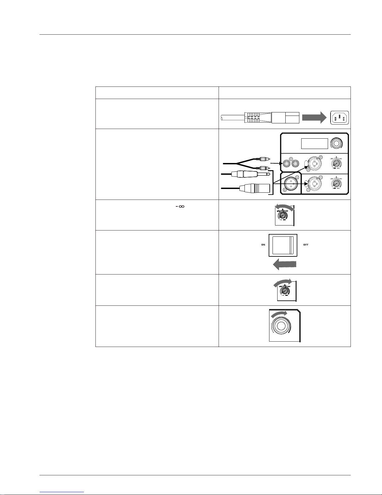
Quick setup
Full-Range loudspeaker
Models: ELX200-10P, ELX200-12P, and
ELX200-15P
To set up a full-range loudspeaker, do the following:
Step Illustration
1. Connect the AC power cord from a
grounded line receptacle to the MAINS
IN.
MAINS IN
2. Connect the XLR, TRS, or RCA cable
from an audio source to INPUT 1 or
INPUT 2.
RL
QuickSmartDSP MONITOR|
AUX IN
OUTPUT
MASTER VOL
INPUT1
INPUT2
PUSH FOR DSP
3. Adjust the input gain to (infinity).
INPUT1INPUT1
4. Switch POWER to ON.
5. From the DSP home screen, increase
the input gain to the desired sound
output.
INPUT1INPUT1
6. Adjust the MASTER VOL
knob to the
desired volume.
MASTER VOL
PUSH FOR D SP
2.3
en 11
Electro-Voice Installation manual 2017.06 | 01 | F.01U.326.891
Page 12

Subwoofer
Models: ELX200-12SP and ELX200-18SP
To
set up a subwoofer, do the following:
Step Illustration
1. Connect the AC power cord from a
grounded line receptacle to the MAINS
IN.
MAINS IN
2. Connect the XLR or TRS cable from an
audio source to INPUT 1 or
INPUT 2.
MASTER VOL
INPUT1
INPUT2
OUTPUT1
OUTPUT2
PUSH FOR DSP
QuickSmartDSP MONITOR|
3. Switch POWER to ON.
4. Adjust the MASTER VOL knob to the
desired volume.
MASTER VOL
PUSH FOR D SP
ELX200 Powered Loudspeakers
2017.06 | 01 | F.01U.326.891 Installation manual Electro-Voice
Page 13
Tripod and floor monitor operation
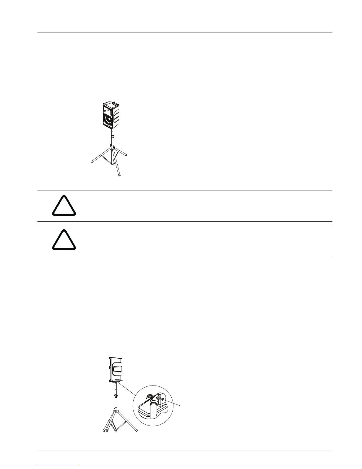
Tripod or pole mount
ELX200-10P, ELX200-12P, and ELX200-15P loudspeakers mount on a tripod stand or on a pole
above a subwoofer.
Mounting a loudspeaker on a tripod stand
Figure 3.1: Full-Range models on a tripod stand
!
Caution!
Tripod is not evaluated for safety with this loudspeaker. Check the specifications of the tripod
stand to be certain it is capable of supporting the weight of the loudspeaker.
!
Caution!
Two person lift and placement is recommended for the heavier loudspeakers. Single person
lift and placement of heavier loudspeakers could cause injury.
To mount a loudspeaker on a tripod stand, do the following:
1. Place the tripod stand
on a level and stable surface.
▪ Fully extend the legs on the tripod stand.
▪ Do not compromise the tripod stands structural integrity by trying to make the stand
taller.
▪ Do not attempt to suspend more than one loudspeaker on a stand designed for a single
loudspeaker.
2. Using two hands lift the loudspeaker.
3. Set the pole cup located on the bottom of the loudspeaker onto the pole.
4. Tighten the thumb screw (A) to secure the loudspeaker to the pole.
The thumb screw is only available on the 12" and 15" full-range loudspeaker models. The 10"
full-range loudspeaker does not have a thumb screw.
A
3
3.1
en 13
Electro-Voice Installation manual 2017.06 | 01 | F.01U.326.891
Page 14
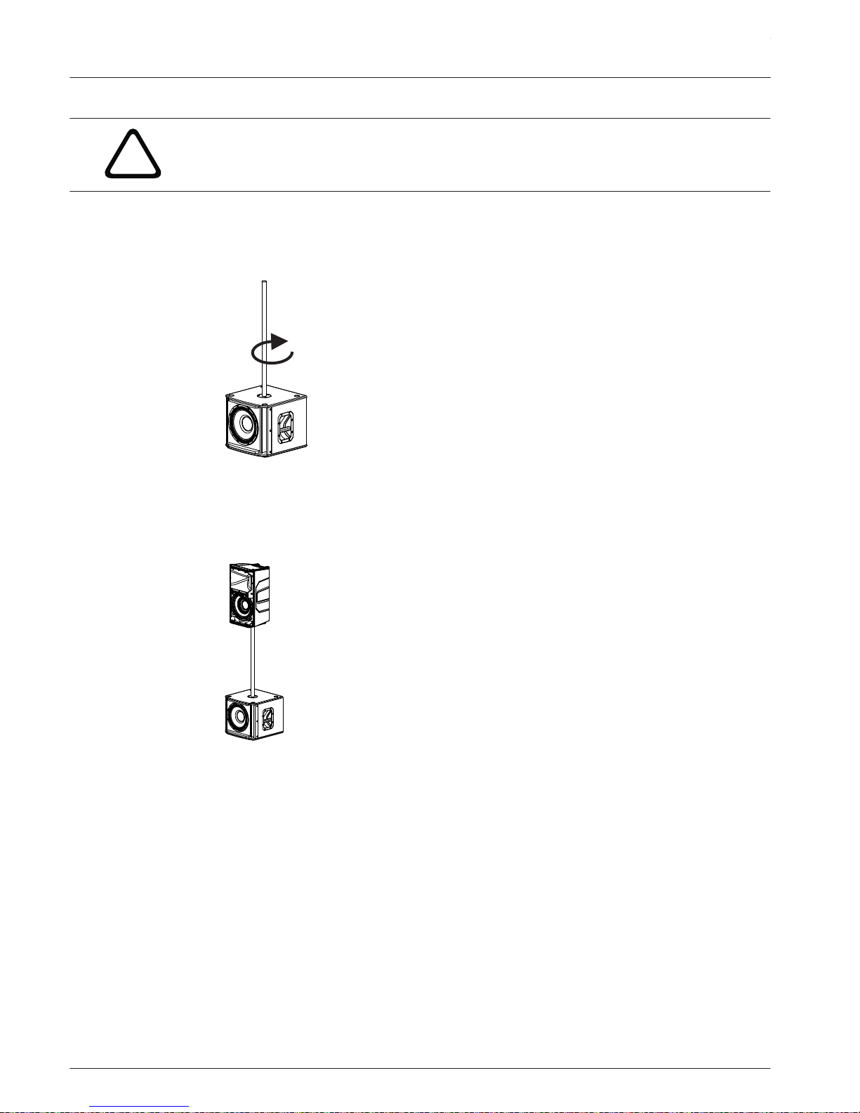
Mounting a loudspeaker on a pole
!
Caution!
Two person lift and placement is recommended for the heavier loudspeakers. Single person
lift and placement of heavier loudspeakers could cause injury.
To mount a loudspeaker on a pole, do the following:
1. Place the subwoofer on a level and stable surface.
2. Insert the M20 threaded pole into the combo pole cup on the top of the subwoofer.
3. Turn the M20 threaded pole clockwise to secure the pole to the subwoofer.
4. Using two hands lift the loudspeaker.
5. Set the
pole cup located on the bottom of the loudspeaker onto the pole.
6. Tighten the thumb screw to secure the loudspeaker to the pole.
The thumb screw is only available on the 12" and 15" full-range loudspeaker models. The 10"
full-range loudspeaker does not have a thumb screw.
See also
• DSP controls, page 22
ELX200 Powered Loudspeakers
2017.06 | 01 | F.01U.326.891 Installation manual Electro-Voice
Page 15

Floor monitor
ELX200-10P, ELX200-12P, and ELX200-15P
loudspeakers may be used as a floor monitor by
placing the loudspeaker on the integral monitor angle.
To set up a loudspeaker as a floor monitor, do the following:
1. Place the loudspeaker on a level and stable surface.
2. Safely route cables to prevent injury to performers, production crew, and audience
members.
Notice!
Secure cables with wire ties or tape whenever possible.
90°
50°
60°
OPTIMAL
COVERAGE
OPTIMAL
COVERAGE
Figure 3.2: Optimum coverage in monitor position (side view left and front view right)
See also
• Full-Range loudspeaker DSP control menu, page 22
3.2
en 15
Electro-Voice Installation manual 2017.06 | 01 | F.01U.326.891
Page 16

Suspension
The ELX200 enclosures have three M10 threaded points; two points on top of the enclosure
and one point on the bottom. Forged shoulder eyebolts rated for overhead suspension may be
used to suspend an individual loudspeaker, such as the EBK1-M10-3PACK accessory.
!
Warning!
Suspending any object is potentially dangerous and should only be attempted by individuals
who have a thorough knowledge of the techniques and regulations of suspending objects
overhead. Electro-Voice strongly recommends all loudspeakers be suspended taking into
account all current national, federal, state, and local laws and regulations. It is the
responsibility of the installer to ensure all loudspeakers are safely installed in accordance
with all such requirements. When loudspeakers are suspended, Electro-Voice strongly
recommends the system be inspected at least once per year or as laws and regulations
require. If any sign of weakness or damage is detected, remedial action should be taken
immediately. The user is responsible for making sure the wall, ceiling, or structure is capable
of supporting all objects suspended overhead. Any hardware used to suspend a loudspeaker
not associated with Electro-Voice is the responsibility of others.
A
B
Figure 4.1: Suspension points (A top, B bottom)
Prior to use, inspect the suspension points and associated hardware for any cracks,
deformations, broken welds, corrosion, missing or damaged components which could reduce
the suspension points strength. Replace any damaged hardware. Never exceed the limitations
or maximum recommended load intended for the suspension points. As an added safety
measure, it is suggested the user install an extra suspension point back to the building
structural supports. This redundant safety point should have as little slack as possible (less
than one inch is preferable). Prior to each use, inspect the loudspeaker enclosures for any
cracks, deformations, missing or damaged components, which could reduce enclosure
strength. Replace any loudspeaker systems damaged or missing hardware.
4
ELX200 Powered Loudspeakers
2017.06 | 01 | F.01U.326.891 Installation manual Electro-Voice
Page 17

Installing the eyebolts
To install the eyebolts, do the following:
1. Remove the three fly point covers
from the suspension points.
2. Install M10 eyebolts and fender washers into the suspension points.
!
Warning!
Eyebolts must be fully seated and oriented in the plane of pull. Always use fender washers at
least 1.5 inch in diameter and 1/16 inch thick under the eyebolt to distribute the load on the
enclosure.
B
A
Figure 4.2: Eyebolt shown with washers (A) and without washers (B)
en 17
Electro-Voice Installation manual 2017.06 | 01 | F.01U.326.891
Page 18

Figure 4.3: Eyebolts shown orientated in the plane of pull (left correct, right incorrect)
!
Warning!
Never exceed the limitations or maximum recommended working load for Electro-Voice
loudspeakers.
Disregarding this warning could result in serious injury or death.
5° MAX
5° MAX
5° MAX
5° MAX
90°
10°
90°
Figure 4.4: Maximum working load - vertical orientation 50 lb per suspension point
!
Warning!
Never suspend ELX200 Series loudspeakers in a vertical column array.
Disregarding this warning could result in serious injury or death.
Figure 4.5: Loudspeaker vertical suspension (Correct, left; Incorrect, right)
See also
• Full-Range loudspeaker DSP control menu, page 22
ELX200 Powered Loudspeakers
2017.06 | 01 | F.01U.326.891 Installation manual Electro-Voice
Page 19

Amplifier DSP
Amplifier DSP controls
The amplifier has a combination of controls and connectors to ensure the most versatile
loudspeaker system.
Full-Range loudspeaker control and monitoring interface
The full-range loudspeaker DSP control menu selections are available for the ELX200-10P,
ELX200-12P, and
ELX200-15P.
RL
QuickSmartDSP MONITOR|
AUX IN
OUTPUT
MASTER VOL
INPUT1
INPUT2
PUSHFOR D SP
ELX200
WARNING: ,TOREDUCE RI SK OF SHOCK DONOT
.EXPOSETHI S APPLIANCE TO RAIN OR MOISTURE
MAINS IN
CAUTION
RISK OF ELECTRIC SHOCK
DO NOT OPEN
RISQUE DE CHOC ELECTRIQUE NE
PAS OUVRIR
AVIS
1
2
3
4
8
7
5
6
Figure 5.1: Full-Range loudspeaker amplifier panel
1. LCD – DSP control and monitoring interface.
2. MASTER VOL – Adjusts the sound level.
DSP – Scroll through the menu and select the available choices. Push the MASTER VOL
knob to enter the DSP menu.
3. INPUT LEVEL – Level control for adjusting the individual inputs’ level. The 12 o’clock
position is unity gain (no gain or attenuation), the range to the left of zero (0) is for
adjusting line level sources, and the range to the right of zero (0) is for adjusting
microphone levels. LINE and MIC input level control is available for both INPUT 1 and
INPUT 2.
4. INPUT – Balanced input for the connection of signal sources like mixing consoles,
instruments, or microphones. Connections can be established using ¼ inch TRS or XLR
connectors.
5. POWER – AC switch for switching the power ON or OFF. The LCD screen lights up when
the power is turned ON, after approximately 3 seconds.
6. MAINS IN – AC connection is established via an IEC-connector.
7. OUTPUT
– XLR output sends the mix of both input signals to another loudspeaker or
subwoofer. INPUT LEVEL controls the signal level to OUTPUT. The MASTER VOL or DSP
control settings do not affect OUTPUT.
5
5.1
en 19
Electro-Voice Installation manual 2017.06 | 01 | F.01U.326.891
Page 20

8. AUX INPUT – Stereo unbalanced RCA inputs for connecting external audio media devices,
such as MP3 players. Both RCA inputs are summed and can be controlled with INPUT 1
level. The inputs can be used simultaneously with XLR/TRS INPUT 1.
Subwoofer control and monitoring interface
The subwoofer DSP control menu selections are available for the ELX200-12SP
and
ELX200-18SP.
MAINS IN
MASTER VOL
INPUT1
INPUT2
OUTPUT1 OUTPUT
2
PUSHF OR DSP
WARNING: ,TOREDUCE R ISK OF SHOCK DONOT
.EXPOSETH IS APPLIANCE TO RAI N OR MOISTURE
CAUTION
RISK OF ELECTRIC SHOCK
DO N
OT OPEN
RISQUE DE CHOC ELECTRIQUE NE
PAS OUVRIR
AVIS
QuickSmartDSP MONITOR|
ELX200
1
2
3
4
5
6
Figure 5.2: Subwoofer amplifier panel
1. LCD – DSP control and monitoring interface.
2. MASTER VOL – Adjusts the sound level.
DSP – Scroll through the menu and select the available choices. Push the MASTER VOL
knob to enter the DSP menu.
3. INPUT – Balanced input for the connection of signal sources like mixing consoles,
instruments, or microphones. Connections can be established using ¼ inch TRS or XLR
connectors.
4. POWER – AC switch for switching the power ON or OFF. The LCD screen lights up when
the power is turned ON, after approximately 3 seconds.
5. MAINS IN – AC connection is established via an IEC-connector.
6. OUTPUT
– XLR output sends the input signal to another loudspeaker or subwoofer.
INPUT 1 is linked to OUTPUT 1 and INPUT 2 is linked to OUTPUT 2. The MASTER VOL or
DSP control settings do not affect OUTPUT.
ELX200 Powered Loudspeakers
2017.06 | 01 | F.01U.326.891 Installation manual Electro-Voice
Page 21

System status
Normal
Figure 5.3: Normal system status home screen with Bluetooth® status
1. LEVEL – Indicates the master gain of the system in dB. The range is from mute to +10 dB,
in 1 dB increments.
2. IN1 – VU meter displays the signal level of INPUT 1 into the amplifier INPUT 1 XLR
connector. IN1 and IN2 are independent of each other.
3. IN2 – VU meter displays the signal level of INPUT 2 into the amplifier INPUT 2 XLR
connector. IN1 and IN2 are independent of each other.
4. C - Control app; the available options are:
OFF - DISABLED
FLASHING - PAIRING MODE
SOLID - CONNECTED
5. 1 - Indicates the selected preset number. There are five user defined presents available.
6. E - Indicates the preset is not saved. When the preset is saved the E is not displayed.
Notice!
Bluetooth® is available in select countries.
Contact your nearest
Electro-Voice
dealer or Electro-Voice distributor for more information.
System protection
System protection limiters indicate when a system is exceeding recommended usage by
indicating CLIP or LIMIT on the LCD display.
CLIP
Figure 5.4: Clipping system status
CLIP indicates the signal to the loudspeaker is too high, resulting in a clipped signal into the
loudspeaker. If CLIP is shown, reduce the input gain knob and/or the signal on the mixer or
source equipment.
LIMIT
OR
Figure 5.5: Limit system status
5.2
en 21
Electro-Voice Installation manual 2017.06 | 01 | F.01U.326.891
Page 22

LIMIT protects the loudspeaker from short-term peaks which can cause distortion. When
LIMIT is shown small on the screen, the limiter is active but keeps distortion under control.
The large LIMIT indicates the sound is negatively affected. Reducing the output volume
(MASTER VOL) is strongly recommended when the large limit indication is shown.
DSP controls
An integrated DSP control menu allows the user to select multiple DSP system settings on the
loudspeaker.
QuickSmartDSP MONITOR|
MASTER VOL
PUSH FO R DSP
Accessing the DSP control menu
To access the DSP controls menu, do the following:
1. Push the MASTER VOL knob
.
The DSP Control menu appears.
2. Using the MASTER VOL knob, scroll through the menu items.
3. Push the MASTER VOL knob to select the menu item you want to modify.
The focus moves to the parameters on the right side of the DSP menu.
4. Using the MASTER VOL knob, scroll through the parameters.
5. Push the MASTER VOL knob to confirm the selected parameter.
The setting is saved. The focus returns to the menu items on the left side of the DSP menu.
6. Repeat steps 2 through 5 to modify additional DSP and system settings.
7. Select EXIT to return to the home screen.
Full-Range loudspeaker DSP control menu
The full-range loudspeaker DSP control menu selections are available for the ELX200-10P,
ELX200-12P, and
ELX200-15P loudspeakers.
EXIT
MODE MUSIC (Default)
LIVE
SPEECH
CLUB
LOCATION TRIPOD (Default)
MONITOR
WALL
SUSPEND
SUB OFF (Default)
80Hz
100Hz
5.3
5.3.1
ELX200 Powered Loudspeakers
2017.06 | 01 | F.01U.326.891 Installation manual Electro-Voice
Page 23

120Hz
150Hz
ELX200-12SP
ELX200-18SP
ZXA1-SUB
EKX-15SP
EKX-18SP
ELX118P
TREBLE 0 db (Default)
-12 dB to +6 dB
MID 0 db (Default)
-12 dB to +6 dB
BASS 0 db (Default)
-12 dB to +6 dB
LED ON (Default)
OFF
LIMIT
DISPLAY BACK
LCD DIM ON (Default)
OFF
BRIGHT 5 (Default)
1 - 10
CONTRAST 5 (Default)
1 - 10
BACK
STORE EXIT, 1, 2, 3, 4, 5, EXIT
RECALL EXIT, 1, 2, 3, 4, 5, EXIT
LOCK NO (Default)
YES
CONTROL APP ON
OFF (Default)
RESET RESET ARE YOU SURE?
NO (Default)
YES
en 23
Electro-Voice Installation manual 2017.06 | 01 | F.01U.326.891
Page 24

INFO [PRODUCT NAME]
[FIRMWARE VERSION]
©2017 Electro-Voice
EXIT
Table 5.1: Full-Range Loudspeaker DSP Control Menu
EXIT Menu
The Exit menu is used to return to the home screen.
Notice!
The display returns to the home screen after two minutes of inactivity.
MODE Menu
The Mode menu is used to configure the type of sound the loudspeaker delivers.
Available options for this selection are: MUSIC, LIVE, SPEECH and CLUB.
▪ MUSIC – is used for recorded music playback and electronic dance music applications.
(Default)
▪ LIVE – is used for live sound applications.
▪ SPEECH – is used for spoken word applications.
▪ CLUB – is used for recorded electronic music playback.
The default is MUSIC
.
LOCATION Menu
The Location menu is used to optimize the loudspeaker for different boundaries.
Available options for this selection are: TRIPOD, MONITOR, WALL, and SUSPEND.
▪ TRIPOD – is used when the loudspeaker is placed on a tripod stand or placed on a pole.
(Default)
▪ MONITOR – is used when the loudspeaker is placed on the angled monitor panel in
monitor position. This setting compensates for the amount of low frequency boost
created by placing the speaker close to the floor.
▪ WALL – is used when the loudspeaker is mounted to the wall using the mounting bracket
(Mounting Bracket accessory sold separately). This setting compensates for the amount
of low frequency boost created by placing the loudspeaker close to the wall. If used on a
column, it is recommended to use the SUSPEND mode.
▪ SUSPEND – is used when the loudspeaker is suspended in a 3-point suspension by
eyebolts.
The default is TRIPOD.
SUB Menu
The Sub menu is used to select a high pass frequency for use with a subwoofer or a matched
subwoofer.
Available options for this selection are: OFF, 80Hz, 100Hz, 120Hz, 150Hz, ELX200-12SP,
ELX200-18SP, ZXA1-SUB, EKX-15SP, EKX-18SP, and ELX118P. The high passes are 24 dB/
octave Linkwitz/Riley crossovers. The 80 Hz, 100 Hz, 120 Hz, and 150 Hz choices are generic
high pass settings for use with other subwoofers. The ELX200-12SP, ELX200-18SP, ZXA1-SUB,
EKX-15SP, EKX-18SP, and ELX118P settings are specifically optimized for subwoofers by
including delay for best summation.
The default is OFF.
ELX200 Powered Loudspeakers
2017.06 | 01 | F.01U.326.891 Installation manual Electro-Voice
Page 25

TREBLE Menu
The Treble menu is used to adjust the high frequency performance of the loudspeaker for
different applications or personal preference. The parameter controls a high shelving filter
that is centered on 6 kHz.
The default is zero (0).
MID Menu
The MID menu is used to adjust the midrange frequency performance of the loudspeaker for
different applications or personal preference. The parameter controls a parametric EQ that is
centered on 1.8 kHz.
The default is zero (0).
BASS Menu
The Bass menu is used to adjust the low frequency performance of the loudspeaker for
different applications or personal preference. The parameter controls a parametric EQ filter
that is centered on 60 Hz.
The default is zero (0).
LED Menu
The LED menu shows power on and indicates limit. Available options for this selection are:
ON, OFF or LIMIT.
▪ ON
– turns the LED on when the power to the loudspeaker is ON. (Default)
▪ OFF
– turns the LED off.
▪ LIMIT – turns the LED off under normal operation. The LED brief blinking indicates the
limiter is activating. Short-term blinking is not critical because the integrated limiter
keeps distortion under control. Constant lighting of the LED indicates the sound is
negatively affected. If the LED is constantly lit, check the rear LCD for more information.
Reducing the output volume is strongly recommended.
LCD DIM Menu
The LCD Dim menu is used to dim the display when the display is idle for two minutes.
Available options for this selection are: ON or OFF.
The default is ON.
BRIGHT Menu
The Bright menu is used to determine the brightness of the LCD.
The range is 1 to 10.
The default is five (5).
CONTRAST Menu
The Contrast menu is used to increase or decrease the visibility of the LCD screen.
The range is 1 to 10.
The default is five (5).
STORE Menu
The Store menu allows you create up to five customized user settings. Available options for
this selection are: EXIT, 1, 2, 3, 4, and 5.
Notice!
The customized user setting name can contain a combination of alphanumeric characters
including spaces. The alphanumeric character range is A to Z and 0-9.
The name field length is 12 characters.
Storing customized user settings
To store customized user settings, do the following:
1.
From the DSP menu, scroll to STORE.
en 25
Electro-Voice Installation manual 2017.06 | 01 | F.01U.326.891
Page 26

2. Push the MASTER VOL knob to select STORE.
The store screen appears.
3.
Push the MASTER VOL knob to select 1.
The Enter name for 1 screen appears.
4. Use the MASTER VOL knob to scroll through the characters.
The characters appear.
5. Push the MASTER VOL knob to select the desired character.
6. Turn the MASTER VOL knob to move to the next character entry.
Continue selecting characters until the desired name is entered.
7. Use the MASTER VOL knob to scroll to SAVE.
8. Push the MASTER VOL knob to select SAVE.
9. Repeat steps 3 through 8 to store additional customized user settings.
10. Select EXIT to return to the home screen.
RECALL Menu
The Recall menu allows you retrieve up to five customized user settings. Available options for
this selection are: EXIT, 1, 2, 3, 4, and 5.
Recalling customized user settings
To recall customized user settings, do the following:
1. From the DSP menu, scroll to RECALL.
2. Push the MASTER VOL knob to select RECALL.
The recall screen appears.
3. Push the MASTER VOL knob to select 1.
The selected item is loaded.
4. Select EXIT to return to the home screen.
LOCK Menu
The Lock menu is designed to prevent users from inadvertently changing settings. Available
options for this selection are: NO or YES.
The default is NO.
Locking the DSP menu
To lock the DSP menu, do the following:
1. From the DSP menu, scroll to LOCK.
2. Select ON.
Notice!
If menu lock is ON, the user is allowed to adjust the MASTER VOL.
Unlocking the DSP menu
To unlock the DSP menu, do the following:
> Press and hold the MASTER VOL knob for three seconds.
The DSP menu unlocks.
CONTROL APP Menu
The Control App menu is used to enable the QuickSmart Mobile wireless control and
monitoring application. Available options for this selection are: ON or OFF.
The default is OFF.
Notice!
Bluetooth® is available in select countries.
Contact your nearest
Electro-Voice
dealer or Electro-Voice distributor for more information.
ELX200 Powered Loudspeakers
2017.06 | 01 | F.01U.326.891 Installation manual Electro-Voice
Page 27

The Bluetooth® word mark and logos are registered trademarks owned by Bluetooth SIG, Inc.
and any use of such marks by Bosch Security Systems, Inc. is under license. Other trademarks
and trade names are those of their respective owners.
Turning Bluetooth® ON or OFF
To turn Bluetooth® ON or OFF, do the following:
1. From the DSP menu, scroll to CONTROL APP
.
2. Select ON.
OR
Select OFF.
RESET Menu
The Reset menu is used to reset the loudspeaker to original factory settings. Available options
for this selection are: NO or YES.
The default is NO.
Resetting the system
To reset the system to original factory settings, do the following:
1. From the DSP menu, select RESET.
The reset "Are you sure?" message appears.
2. Select YES.
The loudspeaker restarts and resets the system to the original factory settings.
Notice!
The reset menu item is used to revert the loudspeaker to the original factory default settings.
All user settings will be deleted. The user customized settings in the STORE and RECALL
menus return to <EMPTY>.
INFO Menu
The Information menu is used to display the product name and firmware version.
Subwoofer DSP control menu
The subwoofer DSP control menu selections are available for the ELX200-12SP and
ELX200-18SP
subwoofers.
EXIT
MODE MUSIC (Default)
LIVE
CLUB
LOW PASS 80Hz
100Hz (Default)
120Hz
150Hz
ELX200-10P
ELX200-12P
ELX200-15P
ZXA1
5.3.2
en 27
Electro-Voice Installation manual 2017.06 | 01 | F.01U.326.891
Page 28

EKX-12P
EKX-15P
ELX112P
ELX115P
ZLX-12P
ZLX-15P
LED ON (Default)
OFF
LIMIT
DISPLAY BACK
LCD DIM ON (Default)
OFF
BRIGHT 5 (Default)
1 to 10
CONTRAST 5 (Default)
1 to 10
BACK
STORE EXIT, 1, 2, 3, 4, 5, EXIT
RECALL EXIT, 1, 2, 3, 4, 5, EXIT
LOCK NO (Default)
YES
CONTROL APP ON
OFF (Default)
RESET RESET ARE YOU SURE?
NO (Default)
YES
INFO [PRODUCT NAME]
[FIRMWARE VERSION]
©2017 Electro-Voice
EXIT
Table 5.2: Subwoofer DSP Control Menu
EXIT Menu
The Exit menu is used to return to the home screen.
ELX200 Powered Loudspeakers
2017.06 | 01 | F.01U.326.891 Installation manual Electro-Voice
Page 29

Notice!
The display returns to the home screen after two minutes of inactivity.
MODE Menu
The Mode menu is used to configure the type of sound the subwoofer delivers.
▪ MUSIC – is used for recorded music playback and electronic dance music applications.
(Default)
▪ LIVE
– is used for live sound applications.
▪ CLUB – is used for recorded electronic music playback.
LOW PASS Menu
The LOW PASS menu is used to select low pass frequency for proper summation with a fullrange loudspeaker.
The low passes are 24 dB/octave Linkwitz/Riley slopes. The 80 Hz, 100 Hz, 120 Hz, and 150 Hz
selections are generic low pass settings for use with other full-range loudspeaker systems. The
ELX200-10P, ELX200-12P, ELX200-15P, ZXA1, EKX-12P, EKX-15P, ELX112P, ELX115P,
ZLX-12P , and ZLX-15P settings are specifically optimized for full-range loudspeakers for best
summation.
The default is 100 Hz.
LED Menu
The LED menu shows power on and indicates limit. Available options for this selection are:
ON, OFF or LIMIT.
▪ ON – turns the LED on when the power to the loudspeaker is ON. (Default)
▪ OFF – turns the LED off.
▪ LIMIT – turns the LED off under normal operation. The LED brief blinking indicates the
limiter is activating. Short-term blinking is not critical because the integrated limiter
keeps distortion under control. Constant lighting of the LED indicates the sound is
negatively affected. If the LED is constantly lit, check the rear LCD for more information.
Reducing the output volume is strongly recommended.
The default is ON.
LCD DIM Menu
The LCD Dim menu is used to dim the display when the display is idle for two minutes.
Available options for this selection are: ON or OFF.
The default is ON.
BRIGHT Menu
The Bright menu is used to determine the brightness of the LCD.
The range is 1 to 10.
The default is five (5).
CONTRAST Menu
The Contrast menu is used to increase or decrease the visibility of the LCD screen.
The range is 1 to 10.
The default is five (5).
STORE Menu
The Store menu allows you create up to five customized user settings. Available options for
this selection are: EXIT, 1, 2, 3, 4, and 5.
en 29
Electro-Voice Installation manual 2017.06 | 01 | F.01U.326.891
Page 30

Notice!
The customized user setting name can contain a combination of alphanumeric characters
including spaces. The alphanumeric character range is A to Z and 0-9.
The name field length is 12 characters.
Storing customized user settings
To store customized user settings, do the following:
1. From the DSP menu, scroll to STORE.
2. Push the MASTER VOL knob to select STORE.
The store screen appears.
3. Push the MASTER VOL knob to select 1.
The Enter name for 1 screen appears.
4. Use the MASTER VOL knob to scroll through the characters.
The characters appear.
5. Push the MASTER VOL knob to select the desired character.
6. Turn the MASTER VOL knob to move to the next character entry.
Continue selecting characters until the desired name is entered.
7. Use the MASTER VOL knob to scroll to SAVE.
8. Push the MASTER VOL knob to select SAVE.
9. Repeat steps 3 through 8 to store additional customized user settings.
10. Select EXIT to return to the home screen.
RECALL Menu
The Recall menu allows you retrieve up to five customized user settings. Available options for
this selection are: EXIT, 1, 2, 3, 4, and 5.
Recalling customized user settings
To recall customized user settings, do the following:
1. From the DSP menu, scroll to RECALL.
2. Push the MASTER VOL knob to select RECALL.
The recall screen appears.
3. Push the MASTER VOL knob to select 1.
The selected item is loaded.
4. Select EXIT to return to the home screen.
LOCK Menu
The Lock menu is designed to prevent users from inadvertently changing settings. Available
options for this selection are: NO or YES.
The default is NO.
Locking the DSP menu
To lock the DSP menu, do the following:
1. From the DSP menu, scroll to LOCK.
2. Select ON.
Notice!
If menu lock is ON, the user is allowed to adjust the MASTER VOL.
Unlocking the DSP menu
To unlock the DSP menu, do the following:
> Press and hold the MASTER VOL knob for three seconds.
The DSP menu unlocks.
ELX200 Powered Loudspeakers
2017.06 | 01 | F.01U.326.891 Installation manual Electro-Voice
Page 31

CONTROL APP Menu
The Control App menu is used to enable the QuickSmart Mobile wireless control and
monitoring application. Available options for this selection are: ON or OFF.
The default is OFF
.
Notice!
Bluetooth® is available in select countries.
Contact your nearest
Electro-Voice
dealer or Electro-Voice distributor for more information.
The Bluetooth® word mark and logos are registered trademarks owned by Bluetooth SIG, Inc.
and any use of such marks by Bosch Security Systems, Inc. is under license. Other trademarks
and trade names are those of their respective owners.
Turning Bluetooth® ON or OFF
To turn Bluetooth® ON or OFF, do the following:
1. From the DSP menu, scroll to CONTROL APP
.
2. Select ON.
OR
Select OFF.
RESET Menu
The Reset menu is used to reset the loudspeaker to original factory settings. Available options
for this selection are: NO or YES.
The default is NO.
Resetting the system
To reset the system to original factory settings, do the following:
1. From the DSP menu, select RESET.
The reset "Are you sure?" message appears.
2. Select YES.
The loudspeaker restarts and resets the system to the original factory settings.
Notice!
The reset menu item is used to revert the loudspeaker to the original factory default settings.
All user settings will be deleted. The user customized settings in the STORE and RECALL
menus return to <EMPTY>.
INFO Menu
The Information menu is used to display the product name and firmware version.
en 31
Electro-Voice Installation manual 2017.06 | 01 | F.01U.326.891
Page 32

Pairing the QuickSmart Mobile application
The EV Quick
Smart Mobile app is available for download for the iOS 10 and higher tablets and
smart phones from the iTunes App Store or Android Marshmallow and higher tablets and
smart phones from the Google Play Store.
Notice!
The EV QuickSmart Mobile app is designed to only find speakers from Electro-Voice with
Bluetooth® enabled.
The EV QuickSmart Mobile app will not display other types of Bluetooth® devices, e.g.
phones, laptops, tablets, or headsets.
Notice!
Bluetooth® is available in select countries.
Contact your nearest
Electro-Voice
dealer or Electro-Voice distributor for more information.
Prior to pairing the EV QuickSmart Mobile app with loudspeakers by Electro-Voice
ensure
Bluetooth® is enabled on the smart phone or tablet, and the loudspeaker.
First time pairing:
To pair the loudspeaker with the EV QuickSmart Mobile app, do the following:
1. Open the EV QuickSmart Mobile app.
2. Finding nearby speakers is displayed on the screen
The EV QuickSmart Mobile app is looking for available Bluetooth® enabled Electro-Voice
loudspeakers.
3. The available loudspeakers are displayed on the screen.
The app will display up to eight available loudspeakers.
4.
Tap the loudspeaker you want to pair with the app.
The selected loudspeaker will have a red line under it acknowledging it is selected.
5. Repeat the previous step until all of the desired loudspeakers are selected.
6. Tap the red CONNECT button.
7. The app pairs with the desired loudspeaker.
The app can connect to up to six loudspeakers.
Subsequent pairing:
To pair the loudspeaker with the EV QuickSmart Mobile app, do the following:
1. Tap the EV QuickSmart Mobile app icon.
2. Finding nearby speakers is displayed on the screen
The EV QuickSmart Mobile app is looking for available Bluetooth® enabled Electro-Voice
loudspeakers.
3. The available loudspeakers are displayed on the screen.
The app will display up to eight available loudspeakers.
4.
Tap the loudspeaker you want to pair with the app.
The selected loudspeaker will have a red line under it acknowledging it is selected.
5. Repeat the previous step until all of the desired loudspeakers are selected.
6. Tap the red CONNECT button.
7. The app pairs with the desired loudspeaker.
The app can connect to up to six loudspeakers.
6
ELX200 Powered Loudspeakers
2017.06 | 01 | F.01U.326.891 Installation manual Electro-Voice
Page 33

Recommended configurations
Daisy-chaining full-range systems
LINE and MIC input level control is available for both INPUT 1 and INPUT 2. The 12 o’clock
position is unity gain (no gain or attenuation) and the range to the right of zero (0) is for
adjusting microphone levels.
RL
QuickSmartDSP MONITOR|
AUX IN
OUTPUT
MASTER VOL INPUT1 INPUT 2
PUSHFOR D SP
ELX200
RL
QuickSmartDSP MONITOR|
AUX IN
OUTPUT
MASTER VOL INPUT1 INPUT 2
PUSHFOR D SP
ELX200
Notice!
The direction of the arrow indicates the signal path.
Mode: Speech
Location: Tripod
Sub: Off
Table 7.1: DSP settings loudspeaker on a tripod
See also
• Amplifier DSP controls, page 19
• Full-Range loudspeaker DSP control menu, page 22
7
7.1
en 33
Electro-Voice Installation manual 2017.06 | 01 | F.01U.326.891
Page 34

MP3 player MONO configuration
RL
QuickSmartDSP MONITOR|
AUX IN
OUTPUT
MASTER VOL INPUT1 INPUT 2
PUSHFOR D SP
ELX200
RL
QuickSmartDSP MONITOR|
AUX IN
OUTPUT
MASTER VOL INPUT1 INPUT 2
PUSHFOR D SP
ELX200
Notice!
The direction of the arrow indicates the signal path.
Mode: Music
Location: Tripod
Sub: Off
Table 7.2: DSP settings loudspeaker on a tripod
See also
• Full-Range loudspeaker DSP control menu, page 22
7.2
ELX200 Powered Loudspeakers
2017.06 | 01 | F.01U.326.891 Installation manual Electro-Voice
Page 35

MP3 player STEREO configuration
RL
QuickSmartDSP MONITOR|
AUX IN
OUTPUT
MASTER VOL INPUT1
INPUT2
PUSHFOR D SP
ELX200
RL
QuickSmartDSP MONITOR|
AUX IN
OUTPUT
MASTER VOL INPUT1
INPUT2
PUSHFOR D SP
ELX200
Mode: Music
Location: Tripod
Sub: Off
Table 7.3: DSP settings loudspeaker on a tripod
See also
• Full-Range loudspeaker DSP control menu, page 22
7.3
en 35
Electro-Voice Installation manual 2017.06 | 01 | F.01U.326.891
Page 36

Using full-range systems as monitors
LINE and MIC input level control is available for both INPUT 1 and INPUT 2. The 12 o’clock
position is unity gain (no gain or attenuation) and the range to the right of zero (0) is for
adjusting microphone levels.
RL
QuickSmartDSP MONITOR|
AUX IN
OUTPUT
MASTER VOL INPUT1
INPUT2
PUSHFOR D SP
ELX200
RL
QuickSmartDSP MONITOR|
AUX IN
OUTPUT
MASTER VOL INPUT1
INPUT2
PUSHFOR D SP
ELX200
Notice!
The direction of the arrow indicates the signal path.
Mode: Live
Location: Monitor
Sub: Off
Table 7.4: DSP settings loudspeakers as monitors
See also
• Amplifier DSP controls, page 19
• Full-Range loudspeaker DSP control menu, page 22
7.4
ELX200 Powered Loudspeakers
2017.06 | 01 | F.01U.326.891 Installation manual Electro-Voice
Page 37

Stacking full-range systems with subwoofers
ELX200-15P
ELX200-18SP
RL
QuickSmartDSP MONITOR|
AUX IN
OUTPUT
MASTER VOL INPUT1
INPUT2
PUSHFORDS P
ELX200
RL
QuickSmartDSP MONITOR|
AUX IN
OUTPUT
MASTER VOL INPUT1 INPUT2
PUSHFORDS P
ELX200
MASTER VOL INPUT1
INPUT2
OUTPUT1 OUTPUT 2
PUSHFORDSP
WARNING: ,TOREDUCERISKOFSHOC K D O NOT
.EXPOSETHISAPPLIANCETORAI N OR MOISTUR E
CAUTION
RISK OF ELECTRIC SHOCK
DO NO
T OPEN
RISQUE DE CHOC ELECTRIQUE NE
P
AS OUVRIR
AVIS
QuickSmartDSPMONITOR|
ELX200
MASTER VOL INPUT1
INPUT2
OUTPUT1 OUTPUT
2
PUSHFORDSP
WARNING: ,TOREDUCERISKOFSHOC K D O NOT
.EXPOSETHISAPPLIANCETORAI N OR MOISTUR E
CAUTION
RISK OF ELECTRIC SHOCK
DO NO
T OPEN
RISQUE DE CHOC ELECTRIQUE NE
P
AS OUVRIR
AVIS
QuickSmartDSPMONITOR|
ELX200
Notice!
The direction of the arrow indicates the signal path.
ELX200-15P
Mode: Live
Location: Tripod
Sub: ELX200-18SP
ELX200-18SP
Mode: Live
Location: Normal
Low Pass: ELX200-15P
Table 7.5: DSP settings loudspeaker and subwoofer stacked
See also
• Full-Range loudspeaker DSP control menu, page 22
• Subwoofer DSP control menu, page 27
7.5
en 37
Electro-Voice Installation manual 2017.06 | 01 | F.01U.326.891
Page 38

Troubleshooting
Problem Possible Cause(s) Action
1. No sound Amplifier Connect a known working test loudspeaker to the
amplifier outputs. If there is no sound, verify all the
electronics are on, the signal routing is correct, the
source is active; the volume is turned up, etc.
Correct/repair/replace as necessary. If there is sound,
the problem is wiring.
Wiring Verify you have connected the correct cables to the
amplifier. Play something at a low level through the
amplifier. Connect the test loudspeaker in parallel with
the malfunctioning line. If the sound level is gone or is
very weak, the line has a short in it (possibly a severe
scrape, pinch, or a missed connection). Using the test
loudspeaker, move down the line and test each
connection/junction until you find the problem and
correct it. Observe proper polarity.
2. Poor Low-
Frequency
Response
With SUB menu
cross-over frequency
activated
If no subwoofers are used with the system, select the
OFF position.
3. Intermittent output
such as cracking or
distortion
Faulty connection Check all connections at amplifier and loudspeakers to
ensure they are all clean and tight. If the problem
persists, check the wiring. See problem 1.
4. Constant noise
such as buzzing,
hissing or humming
Defective source or
other electronic
device
If noise is present, but no program material is playing,
evaluate each component as necessary to isolate the
problem. Most likely there is a break in the signal path.
Poor system
grounding or ground
loop
Check and correct the system grounding, as required.
Input gain knob is
not in the MIC
position
Slowly increase the input gain knob level to engage the
microphone pre-amp.
5. No sound produced
with microphone
connected to INPUT
1 or INPUT 2
Microphone requires
phantom power.
Use a dynamic microphone that does not require
phantom power. If using a microphone requiring
phantom power, an external phantom power source is
needed
Input gain knob is
not in the MIC
position
Slowly increase the input gain knob level to engage the
microphone pre-amp.
6. Sound is distorted
front LED is OFF,
LCD screen LIMIT is
ON
Excessive input level Reduce the input level or loudspeaker level knobs to
prevent limit.
8
ELX200 Powered Loudspeakers
2017.06 | 01 | F.01U.326.891 Installation manual Electro-Voice
Page 39

Problem Possible Cause(s) Action
Incorrect gain
structure or source
input (mixing
console/preamp) is
overdriven
Verify level controls of the source are properly structured
by using the VU meter indicator on the LCD screen. If the
VU meter bar is solid or the system indicates LIMIT, the
input or source level is too high.
7. Microphone
produces acoustic
feedback when
input level is
amplified
Incorrect gain
structure
Reduce the microphone levels at the mixing console or
input source. If the microphone is connected directly to
the speaker, reduce the input level on the speaker.
Positioning the microphone close to the sound source
increases gain-before-feedback. See problem 6.
MODE is set to
MUSIC
Change the MODE to LIVE or SPEECH.
Microphone position
is too close to the
front of the
loudspeaker
Whenever possible setup the loudspeakers so the
microphone is behind them. If using the loudspeaker in a
monitor position, aim the loudspeaker to the back of the
microphone.
8. DSP menu is locked The Menu Lock
function has been
turned on. A lock
symbol displays on
the LCD screen.
Press and hold the MASTER VOL knob for 5 seconds.
9. QuickSmart Mobile
app does not
detect the
loudspeaker
Enable Bluetooth® Ensure Bluetooth® is enabled on the loudspeaker.
If these suggestions do not solve your problem, contact your nearest Electro-Voice dealer or
Electro-Voice
distributor.
See also
• System status, page
21
• DSP controls, page 22
en 39
Electro-Voice Installation manual 2017.06 | 01 | F.01U.326.891
Page 40

Technical data
ELX200-10P, ELX200-12P, and ELX200-15P
.
ELX200-10P ELX200-12P ELX200-15P
Freq. Response (-3 dB): 59 Hz – 18 kHz
1
57 Hz – 16 kHz
1
55 Hz – 16 kHz
1
Freq. Range (-10 dB): 53 Hz – 20 kHz
1
51 Hz – 20 kHz
1
48 Hz – 19 kHz
1
Maximum SPL: 130 dB
2
130 dB
2
132 dB
2
Coverage (H x V): 90° x 60°
Power Rating: 1200 W
LF Transducer: EVS-10M 254 mm (10 in) EVS-12M 300 mm (12 in) EVS-15M 381 mm (15 in)
HF Transducer: DH-1C 1-inch titanium compression driver
Crossover Freq.: 1800 Hz 1700 Hz 1600 Hz
Connectors: (1) Stereo RCA Input, (2) XLR/TRS combo jack, and (1) XLR
Enclosure: Polypropylene
Grille: 18 AWG steel with powdercoat
Suspension: (3) M10 suspension points
Color: Black
Dimensions:
mm, (in)
390 x 594 x 394
(15.4 x 23.4 x 15.5)
415 x 664 x 419
(16.3 x 26.1 x 16.5)
500 x 744 x 444
(19.7 x 29.3 x 17.5)
Net Weight: 13.5 kg (29.9 lb) 15.6 kg (34.4 lb) 18.9 kg (41.7 lb)
Shipping Weight: 15.6 kg (34.4 lb) 17.7 kg (39.1 lb) 21.8 kg 48.1 lb)
Power Consumption: 100 - 240 V~, 50 - 60 Hz, 1.8A
3
1
Full space measurement using music DSP preset.
2
Maximum SPL is measured at 1 m using broadband pink noise at maximum output.
3
Current rating is 1/8 power.
ELX200-12SP and ELX200-18SP
ELX200-12SP ELX200-18SP
Freq. Response (-3 dB): 49 Hz – 135 Hz
1
47 Hz – 105 Hz
1
Freq. Range (-10 dB): 41 Hz – 165 Hz
1
40 Hz – 145 Hz
1
Maximum SPL: 129 dB
2
132 dB
2
Power Rating: 1200 W
LF Transducer: EVS-12M 300 mm (12 in) EVS-18M 457 mm (18 in)
Low Pass Frequency: Adjustable: 80 Hz, 100 Hz, 120 Hz, 150 Hz
Connectors: (2) XLR/TRS combo jacks and (2) XLR link outputs
Enclosure: 15 mm plywood with EVCoat
9
ELX200 Powered Loudspeakers
2017.06 | 01 | F.01U.326.891 Installation manual Electro-Voice
Page 41

ELX200-12SP ELX200-18SP
Grille: 18 AWG steel with powdercoat
Color: Black
Dimensions:
mm, (in)
434 x 504 x 490
(17.1 x 19.8 x 19.3)
636 x 598 x 518
(25.0 x 23.5 x 20.4)
Net Weight: 19.1 kg (42.2 lb) 29.0 kg (64 lb)
Shipping Weight: 22.3 kg (49.2 lb) 33.1 kg (73.0 lb)
Power Consumption: 100 - 240 V~, 50 - 60 Hz, 1.8 A
3
1
Half space measurement.
2
Maximum SPL is measured at 1 m using broadband pink noise at maximum output.
3
Current rating is 1/8 power.
Dimensions
330 mm
[13 in]
220 mm
[9 in]
226 mm
[9 in]
319 mm
[13 in]
118 mm
[5 in]
179 mm
[7 in]
273 mm
[11 in]
531 mm
[21 in]
Figure 9.1: ELX200-10P dimensions
363mm
[14in]
155 mm
[6in]
311 mm
[12 in]
629 mm
[25in]
253 mm [10in]
256 mm
[10in]
344 mm
[14 in]
Figure 9.2: ELX200-12P dimensions
423 mm
[17 in]
366 mm
[14 in]
207 mm
[8 in]
710 mm
[28 in]
277 mm
[11 in]
300 mm
[12in]
384 mm
[15 in]
164 mm
[6 in]
Figure 9.3: ELX200-15P dimensions
9.1
en 41
Electro-Voice Installation manual 2017.06 | 01 | F.01U.326.891
Page 42

445 mm
[18 in]
397 mm
[16 in]
225 mm
[9 in]
229 mm
[9 in]
160 mm
[6 in]
223 mm
[9 in]
457 mm
[18 in]
229 mm
[9 in]
222 mm
[9 in]
Figure 9.4: ELX200-12SP dimensions
FRONT VIEW
RIGHT VIEW
REAR VIEW
507 mm
[20 in]
256 mm
[10 in]
229 mm
[9 in]
160 mm [6 in]
275 mm
[11 in]
287 mm
[11 in]
574 mm
[23 in]
TOP VIEW
600 mm
[24 in]
LEFT VIEW
Figure 9.5: ELX200-18SP dimensions
Frequency Response
Figure 9.6: ELX200-10P Frequency response graph: Live, Music, Speech, and Club modes
Figure 9.7: ELX200-12P Frequency response graph: Live, Music, Speech, and Club modes
9.2
ELX200 Powered Loudspeakers
2017.06 | 01 | F.01U.326.891 Installation manual Electro-Voice
Page 43

Figure 9.8: ELX200-15P Frequency response graph: Live, Music, Speech, and Club modes
Figure 9.9: ELX200-12SP Frequency response graph: Live, Music, Speech, and Club modes
Figure 9.10: ELX200-18SP Frequency response graph: Live, Music, Speech, and Club modes
en 43
Electro-Voice Installation manual 2017.06 | 01 | F.01U.326.891
Page 44

Bosch Sicherheitssysteme GmbH
Robert-Bosch-Ring 5
85630 Grasbrunn
Germany
www.boschsecurity.com
© Bosch Sicherheitssysteme GmbH, 2017
Bosch Security Systems, Inc
12000 Portland Avenue South
Burnsville MN 55337
USA
www.electrovoice.com
 Loading...