

Page 1
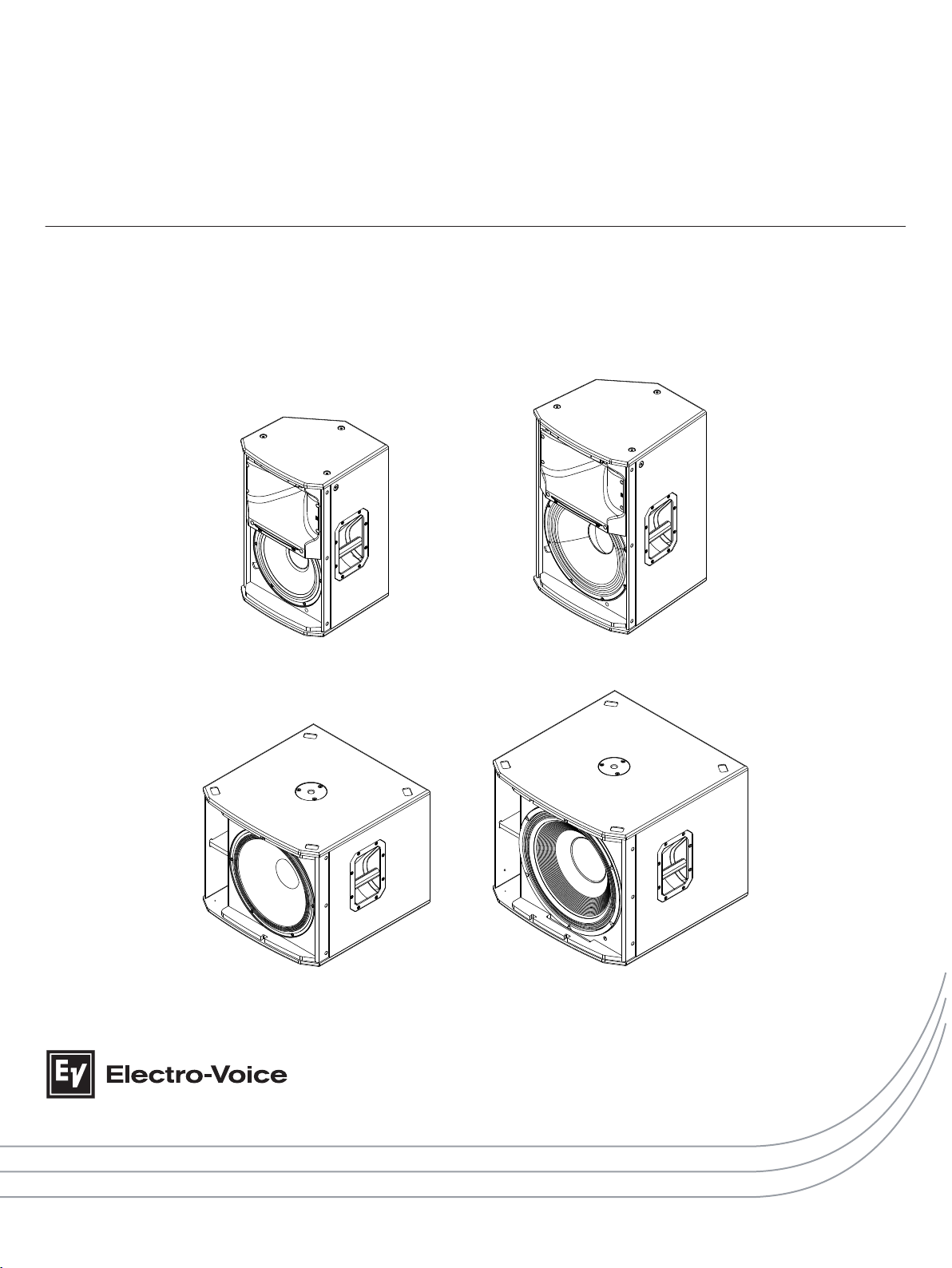
EKX Powered Loudspeakers
EKX-12P, EKX-15P, EKX-15SP, and EKX-18SP
en | User Manual
Page 2

Page 3

Table of contents
en 3
1
1.1 Important Safety Instructions 4
1.2 FCC Information 5
1.3 Precautions 6
1.4 Suspension 6
2
2.1 System features 8
2.2 Quick Setup 9
3
3.1 Dimensions 11
4
4.1 Tripod or pole mount 12
4.2 Floor monitor 14
5
6
6.1 Amplifier DSP controls 19
6.2 System status 21
6.3 DSP controls 22
6.3.1 Full-Range loudspeaker DSP control menu 23
6.3.2 Subwoofer DSP control menu 28
7
7.1 Daisy-chaining full-range systems 33
7.2 MP3 player MONO configuration 34
7.3 MP3 player STEREO configuration 35
7.4 Using full-range systems as monitors 36
7.5 Stacking full-range systems with subwoofers 37
7.6 Cardioid Control Technology 38
8
9
9.1 Frequency response 44
Safety 4
Description 7
System overview 11
Tripod and floor monitor operation 12
Suspension 15
Amplifier DSP 19
Recommended configurations 33
Troubleshooting 40
Technical data 42
Electro-Voice User Manual 2015.02 | 03 | F.01U.308.095
Page 4
!
EKX Powered Loudspeakers
1
1.1
Safety
Important Safety Instructions
WARNING: TO REDUCE THE RISK OF
FIRE OR ELECTRIC SHOCK, DO NOT
OVEREXPOSE THIS APPLIANCE TO
RAIN OR MOISTURE
AVIS: RISQUE DE CHOC ELECTRIQUE,
NE PAS OUVRIR.
WARNING: THE MAINS PLUG OR AC
INLET IS USED AS A DISCONNECT
DEVICE. THE DISCONNECT DEVICE
SHALL REMAIN READILY OPERABLE.
WARNING: CONNECT ONLY TO
MAINS SOCKET WITH PROTECTIVE
EARTHING CONNECTION.
WARNING: TO REDUCE THE RISK OF
ELECTRIC SHOCK, DO NOT REMOVE
COVER (OR BACK) AS THERE ARE NO
USER-SERVICABLE PARTS INSIDE.
REFER SERVICING TO QUALIFIED
PERSONNEL.
The lightening flash with arrowhead
symbol, within an equilateral triangle
is intended to alert the user to the
presence of uninsulated “dangerous
voltage” within the product’s
enclosure that may be sufficient
magnitude to constitute a risk of
electric shock to persons.
The exclamation point within an
equilateral triangle is intended to alert
the user to the presence of important
operating and maintenance (servicing)
instructions in the literature
accompanying the appliance.
The asterisk within an equilateral
triangle is intended to inform the user
to necessary installation or removal
instructions regarding equipment or
hardware use relating to the system.
1. Read these instructions.
2. Keep these instructions.
3. Heed all warnings.
4. Follow all instructions.
5. Do not use this apparatus near water.
6. Clean only with a dry cloth.
7. Do not install near any heat sources such as radiators, heat registers, stoves, or other
apparatus (including amplifiers) that produce heat.
8. Only use attachments/accessories specified by the manufacturer.
9. Do not expose this apparatus to dripping or splashing and ensure that no objects filled
with liquids, such as vases, are placed on this apparatus.
10. Do not block any ventilation openings. Install in accordance with the manufacturers
instructions.
11. Do not defeat the safety purpose of the polarized or grounding-type plug. A polarized plug
has two blades with one wider than the other. A grounding type plug has two blades and
a third grounding prong. The wide blade or the third prong is provided for your safety. If
the provided plug does not fit into your outlet, consult an electrician for replacement of
the obsolete outlet.
12. Protect the power cord from being walked on or pinched particularly at plugs,
convenience receptacles, and the point where they exit from the apparatus.
13. Unplug the apparatus during lightning storms or when unused for long periods of time.
2015.02 | 03 | F.01U.308.095 User Manual Electro-Voice
Page 5
en 5
14. Refer all servicing to qualified service personnel. Servicing is required when the
apparatus has been damaged in any way, such as power-supply cord or plug is damaged,
liquid has been spilled or objects have fallen into the apparatus, the apparatus has been
exposed to rain or moisture, does not operate normally, or has been dropped.
15. To completely disconnect AC power from this apparatus, the power supply cord must be
unplugged.
Old electrical and electronic appliances
Electrical or electronic devices that are no longer serviceable must be collected separately and
sent for environmentally compatible recycling (in accordance with the European Waste
Electrical and Electronic Equipment Directive).
To dispose of old electrical or electronic devices, you should use the return and collection
systems put in place in the country concerned.
1.2
FCC Information
IMPORTANT: Do not modify this unit! Changes or modifications not expressly approved by the
manufacturer could void the user’s authority, granted by the FCC, to operate the equipment.
Notice!
This equipment has been tested and found to comply with the limits for a Class B digital
device, pursuant to Part 15 of the FCC Rules. These limits are designed to provide reasonable
protection against harmful interference in a residential installation. This equipment generates,
uses and can radiate radio frequency energy and, if not installed and used in accordance with
the instructions, may cause harmful interference to radio communications. However, there is
no guarantee interference will not occur in a particular installation. If this equipment does
cause harmful interference to radio or television reception, which can be determined by
turning the equipment off and on, the user is encouraged to try to correct the interference by
one or more of the following measures:
▪ Reorient or relocate the receiving antenna.
▪ Increase the separation between the equipment and receiver.
▪ Connect the equipment into an outlet on a circuit different from that to which the
receiver is connected.
▪ Consult the dealer or an experienced radio/TV technician.
Electro-Voice User Manual 2015.02 | 03 | F.01U.308.095
Page 6
!
!
!
!
!
EKX Powered Loudspeakers
1.3
Precautions
If an Electro-Voice loudspeaker is used outdoors on a sunny day, place the
loudspeaker in a shaded or covered area. The loudspeaker amplifiers have
protection circuits that temporarily shut the loudspeaker off when extremely
high temperatures are reached. This can happen on hot days when the
loudspeaker is in direct sunlight.
Do not use Electro-Voice loudspeakers in an environment where temperatures
are below 0°C (32°F) or exceed +40°C (104°F).
Never expose an Electro-Voice loudspeaker to rain, water, or high moisture.
Electro-Voice loudspeakers are easily capable of generating sound pressure
levels sufficient to cause permanent hearing damage to anyone within normal
coverage distance. Caution should be taken to avoid prolonged exposure to
sound pressure levels exceeding 90 dB.
1.4
Suspension
Warning!
Suspending any object is potentially dangerous and should only be attempted by individuals
who have a thorough knowledge of the techniques and regulations of suspending objects
overhead. Electro-Voice strongly recommends all loudspeakers be suspended taking into
account all current national, federal, state, and local laws and regulations. It is the
responsibility of the installer to ensure all loudspeakers are safely installed in accordance
with all such requirements. When loudspeakers are suspended, Electro-Voice strongly
recommends the system be inspected at least once per year or as laws and regulations
require. If any sign of weakness or damage is detected, remedial action should be taken
immediately. The user is responsible for making sure the wall, ceiling, or structure is capable
of supporting all objects suspended overhead. Any hardware used to suspend a loudspeaker
not associated with Electro-Voice is the responsibility of others.
2015.02 | 03 | F.01U.308.095 User Manual Electro-Voice
Page 7

en 7
2
Description
Thank you for choosing an Electro-Voice powered loudspeaker system. Please take time to
consult the manual to understand all the features built into your EV system and fully utilize its
performance capabilities.
The EKX series is the newest member of the Electro-Voice portable loudspeaker family, and
combines legendary EV sound quality and reliability with the latest technology — all in a
compact package suitable for a wide range of sound reinforcement scenarios, including
musicians/DJs and live/club/installed sound applications. The EKX series features eight (8)
models (four (4) powered and four (4) passive), including 12-inch and 15-inch two-way
models and 15-inch and 18-inch subwoofers.
EV-engineered components, Signal Synchronized Transducers (SST) waveguide design, and
Class D amplifiers (up to 1500 W) coupled with QuickSmartDSP all work together to provide
precise coverage and superior sound quality at high SPLs. EV’s award-winning industrial
design — with robust wood enclosures and durable EVCoat finish — ensures that EKX speakers
look as great as they sound.
Powered EKX models feature high-efficiency Class-D power amplifiers (up to 1500 W) with
integrated QuickSmartDSP, and deliver up to 134 dB SPL utilizing high-sensitivity transducers
designed and engineered by EV (12-inch EVS-12M woofer / 15-inch EVS-15M woofer, each
coupled with a DH-1M 1-inch titanium compression driver; 15-inch EVS-15C subwoofer / 18inch EVS-18C subwoofer).
The EKX amplifier incorporates intelligent thermal management (with a variable-speed fan
controlled by multiple onboard sensors) which ensures superior performance and reliability in
demanding environmental conditions.
Powered models allow easy setup via four (4) presets (Music, Live, Speech*, Club), sub/top
system-match crossovers, three-band EQ*, five (5) user-programmable presets (Store and
Recall settings), visual monitoring of limiter status, input level control* and meters, and
master volume control to ensure optimal gain structure. (* not available on subwoofers)
Adapted from our touring systems, EV’s exclusive Cardioid Control Technology allows output
to be steered towards the audience with up to 35 dB reduction on stage when multiple subs
are deployed.
EKX powered models are ideal for portable and installed applications, with lightweight and
compact 15-mm wood enclosures with internal bracing, durable EVCoat finish, eight (8) M10
threaded mounting points (full-range only), aluminum pole-mounts, and all-metal handles.
Electro-Voice User Manual 2015.02 | 03 | F.01U.308.095
Page 8

EKX Powered Loudspeakers
2.1
System features
EKX-12P – 12-inch two-way powered loudspeaker system
▪ QuickSmartDSP features best-in-class processing, EV’s signature single-knob user
interface, and intuitive menu navigation via LCD.
▪ High-efficiency 1500 W Class-D power amplifier delivers up to 132 dB SPL via high-
sensitivity transducers designed and engineered by EV.
▪ Intelligent thermal management with a
variable-speed fan controlled by multiple onboard sensors.
▪ EV-patented Signal Synchronized Transducers (SST) waveguide design provides precise
and consistent coverage.
▪ Lightweight, compact 15-mm wood enclosure with internal bracing, durable EVCoat
finish, eight (8) M10 threaded mounting points, aluminum
pole-mounts, and all-metal handles.
EKX-15P – 15-inch two-way powered loudspeaker system
▪ QuickSmartDSP features best-in-class processing, EV’s signature single-knob user
interface, and intuitive menu navigation via LCD.
▪ High-efficiency 1500 W Class-D power amplifier delivers up to 134 dB SPL via next-
generation
high-sensitivity transducers designed and engineered by EV.
▪ Intelligent thermal management with a
variable-speed fan controlled by multiple onboard sensors.
▪ EV-patented Signal Synchronized Transducers (SST) waveguide design provides precise
and consistent coverage.
▪ Lightweight, compact 15-mm wood enclosure with internal bracing, durable EVCoat
finish, eight (8) M10 threaded mounting points, aluminum
pole-mounts, and all-metal handles.
EKX-15SP – 15-inch powered subwoofer loudspeaker system
▪ QuickSmartDSP features best-in-class processing, EV’s signature single-knob user
interface, and intuitive menu navigation via LCD.
▪ Cardioid Control Technology allows output to be steered towards the audience with up to
35 dB reduction on stage when multiple subs are deployed.
▪ High-efficiency 1300 W Class-D power amplifier delivers up to 133 dB SPL utilizing high-
sensitivity transducers designed and engineered by EV.
▪ Intelligent thermal management with a
variable-speed fan controlled by multiple onboard sensors.
▪ Two (2) XLR outputs for easy system expansion to additional loudspeakers or
subwoofers. Large slot ports for low distortion and excellent bass extension. Metal grille
reinforcement bar. M20 threaded pole mount plate.
EKX-18SP – 18-inch powered subwoofer loudspeaker system
▪ QuickSmartDSP features best-in-class processing, EV’s signature single-knob user
interface, and intuitive menu navigation via LCD.
▪ Cardioid Control Technology allows output to be steered towards the audience with up to
35 dB reduction on stage when multiple subs are deployed.
▪ High-efficiency 1300 W Class-D power amplifier delivers up to 134 dB SPL utilizing high-
sensitivity transducers designed and engineered by EV.
2015.02 | 03 | F.01U.308.095 User Manual Electro-Voice
Page 9
en 9
▪ Intelligent thermal management with a
variable-speed fan controlled by multiple onboard sensors.
▪ Two (2) XLR outputs for easy system expansion to additional loudspeakers or
subwoofers. Large slot ports for low distortion and excellent bass extension. Two (2)
metal grille reinforcement bar. M20 threaded pole mount plate.
2.2
Quick Setup
The EKX powered loudspeakers from Electro-Voice with carefully matched electronics and
transducers. These products make it easy to set up a high quality system quickly with a
minimum amount of cables and external electronics.
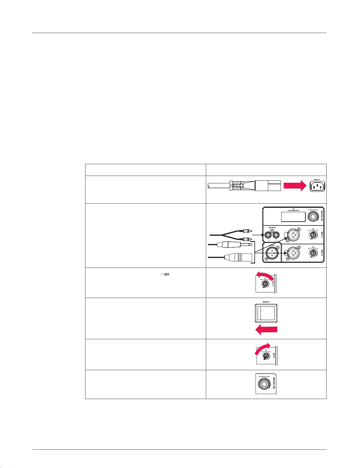
Full-Range loudspeaker
Models: EKX-12P and EKX-15P
To set up a full-range loudspeaker, do the following:
Step Illustration
1. Connect the AC power cord from a
grounded line receptacle to the MAINS
IN.
2. Connect the XLR, TRS, or RCA cable
from an audio source to INPUT 1 or
INPUT 2.
3. Adjust the input gain to (infinity).
4. Switch POWER to ON.
5. From the DSP home screen, increase the
input gain to the desired sound output.
6. Adjust the MASTER VOL knob to the
desired volume.
Electro-Voice User Manual 2015.02 | 03 | F.01U.308.095
Page 10
EKX Powered Loudspeakers
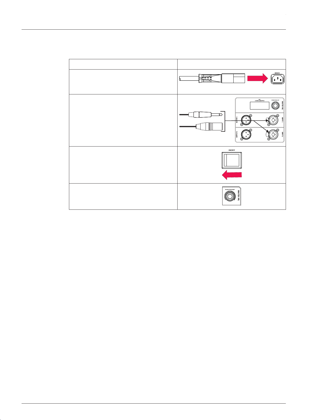
Subwoofer
Models: EKX-15SP and EKX-18SP
To set up a subwoofer, do the following:
Step Illustration
1. Connect the AC power cord from a
grounded line receptacle to the MAINS
IN.
2. Connect the XLR or TRS cable from an
audio source to INPUT 1 or INPUT 2.
3. Switch POWER to ON.
4. Adjust the MASTER VOL knob to the
desired volume.
2015.02 | 03 | F.01U.308.095 User Manual Electro-Voice
Page 11
en 11
3
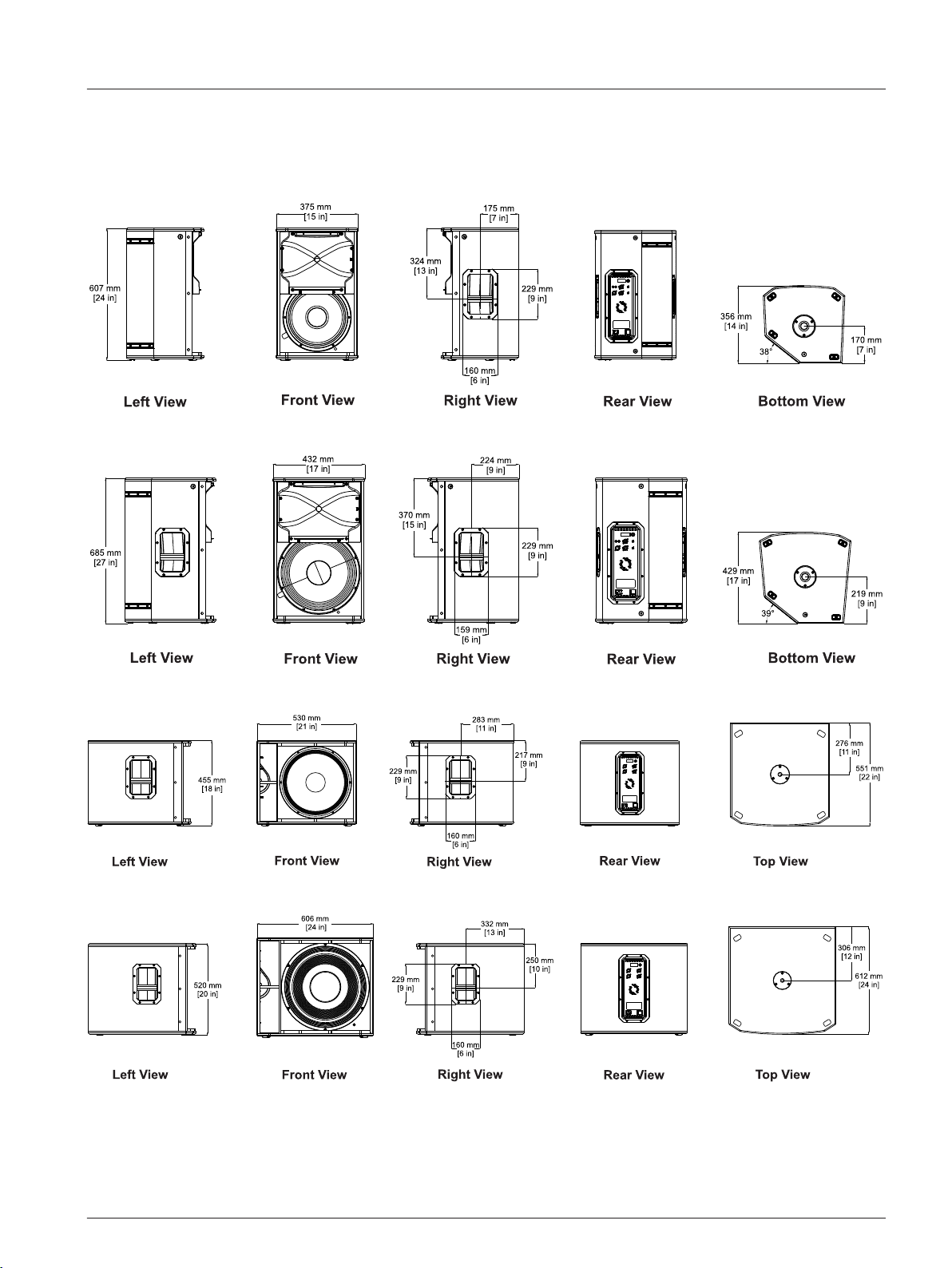
3.1
Figure 3.1: EKX-12P dimensions
System overview
Dimensions
Figure 3.2: EKX-15P dimensions
Figure 3.3: EKX-15SP dimensions
Figure 3.4: EKX-18SP dimensions
Electro-Voice User Manual 2015.02 | 03 | F.01U.308.095
Page 12
!
!
EKX Powered Loudspeakers
4
4.1
Tripod and floor monitor operation
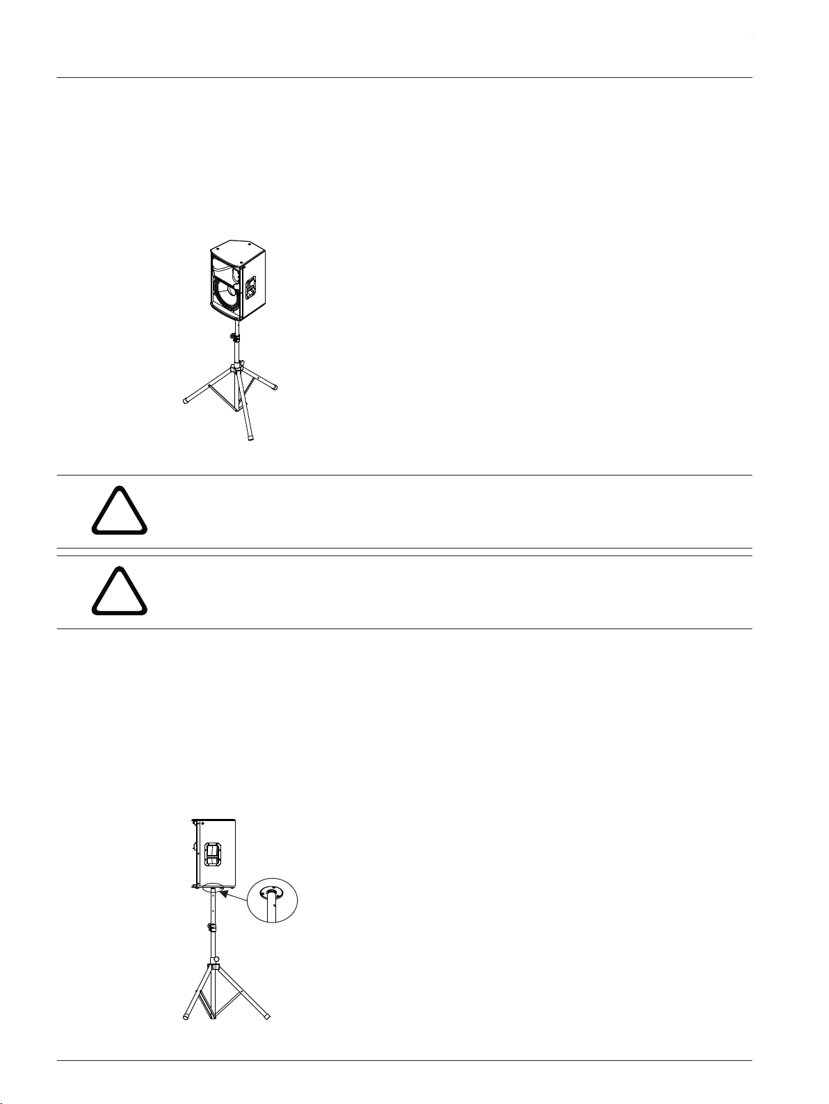
Tripod or pole mount
EKX-12P and EKX-15P loudspeakers mount on a tripod stand or on a pole above a subwoofer.
Mounting a loudspeaker on a tripod stand
Figure 4.1: Full-Range models on a tripod stand
Caution!
Tripod is not evaluated for safety with this loudspeaker. Check the specifications of the tripod
stand to be certain it is capable of supporting the weight of the loudspeaker.
Caution!
Two (2) person lift and placement is recommended for the heavier loudspeakers. Single
person lift and placement of heavier loudspeakers could cause injury.
To mount a loudspeaker on a tripod stand, do the following:
1. Place the tripod stand on a level stable surface.
▪ Fully extend the legs on the tripod stand.
▪ Do not compromise the tripod stands structural integrity by trying to make the stand
taller.
▪ Do not attempt to suspend more than one (1) loudspeaker on a stand designed for a
single loudspeaker.
2. Using two (2) hands lift the loudspeaker.
3. Set the pole cup located on the bottom of the loudspeaker onto the pole.
2015.02 | 03 | F.01U.308.095 User Manual Electro-Voice
Page 13
!
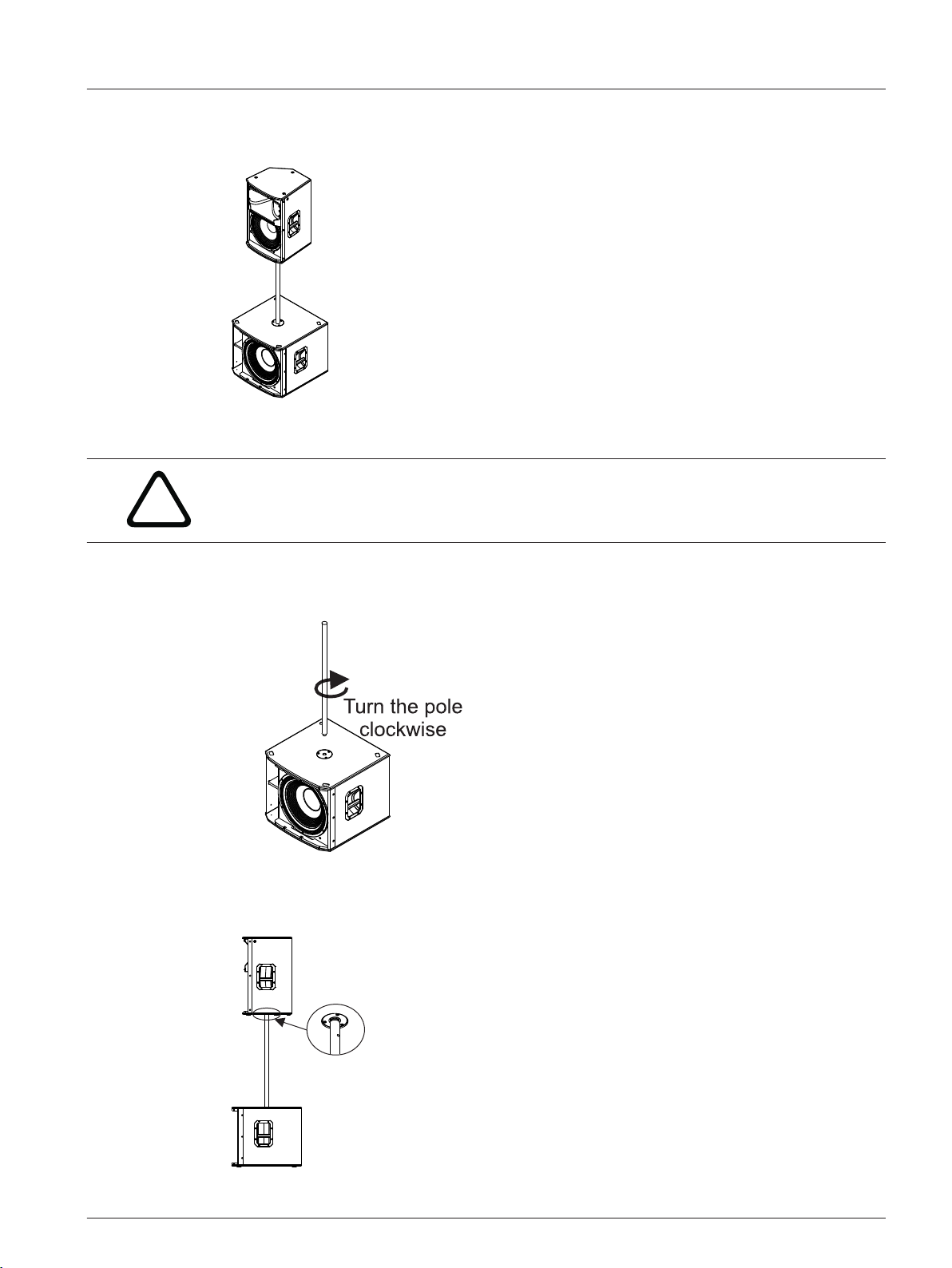
Mounting a loudspeaker on a pole
Figure 4.2: Full-Range/subwoofer stack with pole mount
Caution!
Two (2) person lift and placement is recommended for the heavier loudspeakers. Single
person lift and placement of heavier loudspeakers could cause injury.
To mount a loudspeaker on a pole, do the following:
1. Place the subwoofer on a level stable surface.
2. Insert the M20 threaded pole into the combo pole cup on the top of the subwoofer.
en 13
3. Turn the M20 threaded pole clockwise to secure the pole to the subwoofer.
4. Using two (2) hands lift the loudspeaker.
5. Set the pole cup located on the bottom of the loudspeaker onto the pole.
Electro-Voice User Manual 2015.02 | 03 | F.01U.308.095
Page 14
EKX Powered Loudspeakers
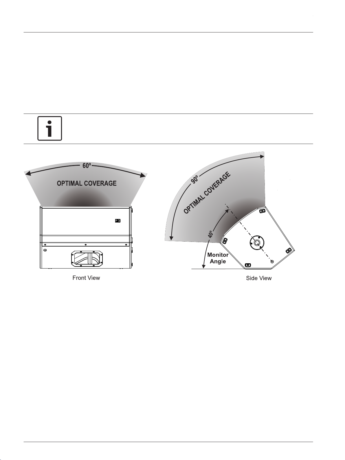
4.2
Floor monitor
EKX-12P and EKX-15P loudspeakers may be used as a floor monitor by placing the loudspeaker
on the integral monitor angle.
To set up a loudspeaker as a floor monitor, do the following:
1. Place the loudspeaker on a level stable surface.
2. Safely route cables to prevent injury to performers, production crew, and audience
members.
Notice!
Secure cables with wire ties or tape whenever possible.
Figure 4.3: Optimum coverage in monitor position
2015.02 | 03 | F.01U.308.095 User Manual Electro-Voice
Page 15
!
en 15
5
Suspension
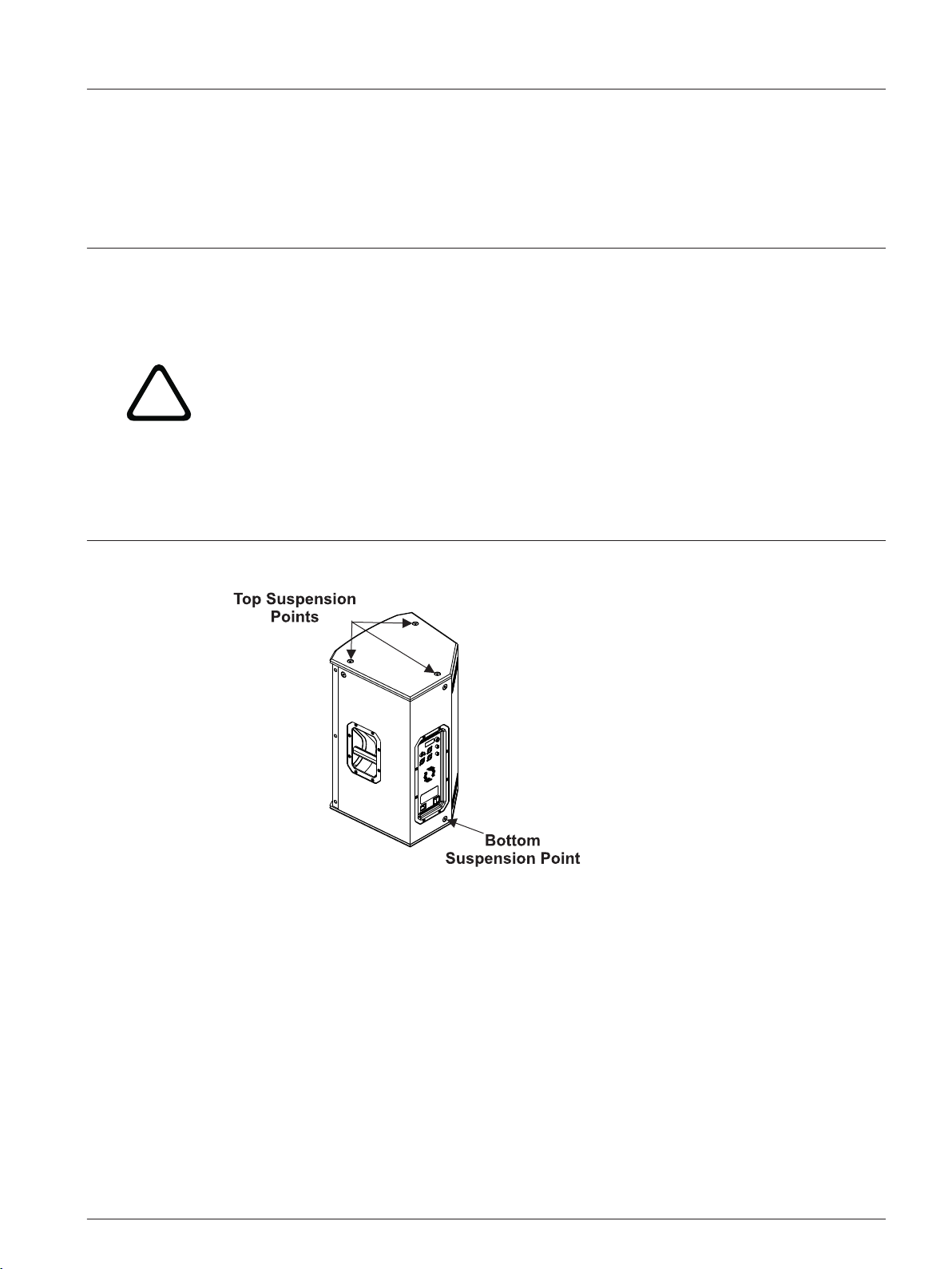
The EKX-12P and EKX-15P enclosures have eight (8) M10 threaded points; six (6) points on
top of the enclosure and two (2) points on the bottom. Forged shoulder eyebolts rated for
overhead suspension may be used to suspend an individual loudspeaker, such as the EBK-M10
accessory.
Warning!
Suspending any object is potentially dangerous and should only be attempted by individuals
who have a thorough knowledge of the techniques and regulations of suspending objects
overhead. Electro-Voice strongly recommends all loudspeakers be suspended taking into
account all current national, federal, state, and local laws and regulations. It is the
responsibility of the installer to ensure all loudspeakers are safely installed in accordance
with all such requirements. When loudspeakers are suspended, Electro-Voice strongly
recommends the system be inspected at least once per year or as laws and regulations
require. If any sign of weakness or damage is detected, remedial action should be taken
immediately. The user is responsible for making sure the wall, ceiling, or structure is capable
of supporting all objects suspended overhead. Any hardware used to suspend a loudspeaker
not associated with Electro-Voice is the responsibility of others.
Figure 5.1: Suspension points
Prior to use, inspect the suspension points and associated hardware for any cracks,
deformations, broken welds, corrosion, missing or damaged components which could reduce
the suspension points strength. Replace any damaged hardware. Never exceed the limitations
or maximum recommended load intended for the suspension points. As an added safety
measure, it is suggested the user install an extra suspension point back to the building
structural supports. This redundant safety point should have as little slack as possible (less
than one (1) inch is preferable). Prior to each use, inspect the loudspeaker enclosures for any
cracks, deformations, missing or damaged components, which could reduce enclosure
strength. Replace any loudspeaker systems damaged or missing hardware.
Electro-Voice User Manual 2015.02 | 03 | F.01U.308.095
Page 16

EKX Powered Loudspeakers
Installing the eyebolts
To install the eyebolts, do the following:
1. Remove the M10 screws from the suspension points.
2. Replace the M10 screw with the fender washer and eyebolts.
Notice!
If the eyebolts are removed reinstall the screws.
If the screws are not reinstalled air leaks occur in the enclosure, resulting in undesirable
performance.
2015.02 | 03 | F.01U.308.095 User Manual Electro-Voice
Page 17

!
en 17
Warning!
Eyebolts must be fully seated and oriented in the plane of pull. Always use fender washers at
least 1.5 inch in diameter and 1/16 inch thick under the eyebolt to distribute the load on the
enclosure.
Figure 5.2: Eyebolt shown with and without washer
Figure 5.3: Eyebolts shown oriented in the plane of pull
Electro-Voice User Manual 2015.02 | 03 | F.01U.308.095
Page 18

!
!
EKX Powered Loudspeakers
Warning!
Never exceed the limitations or maximum recommended working load for Electro-Voice
loudspeakers.
Disregarding this warning could result in serious injury or death.
Figure 5.4: Maximum working load - vertical orientation
Warning!
Never suspend EKX Series loudspeakers in a vertical column array.
Disregarding this warning could result in serious injury or death.
Figure 5.5: Loudspeaker vertical suspension
2015.02 | 03 | F.01U.308.095 User Manual Electro-Voice
Page 19

en 19
6
6.1
Amplifier DSP
Amplifier DSP controls
The amplifier has a combination of controls and connectors to ensure the most versatile
loudspeaker system.
Full-Range loudspeaker control and monitoring interface
The full-range loudspeaker DSP control menu selections are available for the EKX-12P and
EKX-15P.
Figure 6.1: Full-Range loudspeaker amplifier panel
1. LCD – DSP control and monitoring interface.
2. MASTER VOL – Adjusts the sound level.
DSP – Scroll through the menu and select the available choices. Push the MASTER VOL
knob to enter the DSP menu.
3. INPUT LEVEL – Level control for adjusting the individual inputs’ level. The 12 o’clock
position is unity gain (no gain or attenuation), the range to the left of zero (0) is for
adjusting line level sources, and the range to the right of zero (0) is for adjusting
microphone levels. LINE and MIC input level control is available for both INPUT 1 and
INPUT 2.
4. INPUT – Balanced input for the connection of signal sources like mixing consoles,
instruments, or microphones. Connections can be established using ¼ inch TRS or XLR
connectors.
5. POWER – AC switch or switching the power ON or OFF. The LCD screen lights up when
the power is turned ON, after approximately 3 seconds.
6. MAINS IN – AC connection is established via an IEC-connector.
7. OUTPUT – XLR output sends the mix of both input signals to another loudspeaker or
subwoofer. INPUT LEVEL controls the signal level to OUTPUT. The MASTER VOL or DSP
control settings do not affect OUTPUT.
Electro-Voice User Manual 2015.02 | 03 | F.01U.308.095
Page 20

EKX Powered Loudspeakers
8. RCA INPUT – Stereo unbalanced RCA inputs for connecting external audio media devices,
such as MP3 players. Both RCA inputs are summed and can be controlled with INPUT 1
level. The inputs can be used simultaneously with XLR/TRS INPUT 1.
Subwoofer control and monitoring interface
The subwoofer DSP control menu selections are available for the EKX-15SP and EKX-18SP.
Figure 6.2: Subwoofer amplifier panel
1. LCD – DSP control and monitoring interface.
2. MASTER VOL – Adjusts the sound level.
DSP – Scroll through the menu and select the available choices. Push the MASTER VOL
knob to enter the DSP menu.
3. INPUT – Balanced input for the connection of signal sources like mixing consoles,
instruments, or microphones. Connections can be established using ¼ inch TRS or XLR
connectors.
4. POWER – AC switch for switching the power ON or OFF. The LCD screen lights up when
the power is turned ON, after approximately 3 seconds.
5. MAINS IN – AC connection is established via an IEC-connector.
6. OUTPUT – XLR output sends the input signal to another loudspeaker or subwoofer.
INPUT 1 is linked to OUTPUT 1 and INPUT 2 is linked to OUTPUT 2. The MASTER VOL or
DSP control settings do not affect OUTPUT.
2015.02 | 03 | F.01U.308.095 User Manual Electro-Voice
Page 21

en 21
6.2
System status
Normal
Figure 6.3: Normal system status home screen
1. LEVEL – Indicates the master gain of the system in dB. The range is from mute to +10 dB,
in 1 dB increments.
2. IN1 – VU meter displays the signal level of INPUT 1 into the amplifier INPUT 1 XLR
connector. IN1 and IN2 are independent of each other.
3. IN2 – VU meter displays the signal level of INPUT 2 into the amplifier INPUT 2 XLR
connector. IN1 and IN2 are independent of each other.
4. Lock – is designed to prevent users from inadvertently changing settings. Available
options for this selection are: ON or OFF.
The default is OFF.
For more information, see LOCK Menu, page 27.
System protection
System protection limiters indicate when a system is exceeding recommended usage by
indicating CLIP or LIMIT on the LCD display.
CLIP
Figure 6.4: Clipping system status
CLIP indicates the signal to the loudspeaker is too high, resulting in a clipped signal into the
loudspeaker. If CLIP is shown, turn down the signal on the mixer or source equipment.
LIMIT
OR
Figure 6.5: Limit system status
LIMIT protects the loudspeaker from short-term peaks which can cause distortion. When
LIMIT is shown small on the screen, the limiter is active but keeps distortion under control.
The large LIMIT indicates the sound is negatively affected. Reducing the output volume
(MASTER VOL) is strongly recommended when the large limit indication is shown.
Electro-Voice User Manual 2015.02 | 03 | F.01U.308.095
Page 22

EKX Powered Loudspeakers
6.3
DSP controls
An integrated DSP control menu allows the user to select multiple DSP system settings on the
loudspeaker.
To access the DSP controls menu, do the following:
1. Push the MASTER VOL knob.
The DSP Control menu appears.
2. Using the MASTER VOL knob, scroll through the menu items.
3. Push the MASTER VOL knob to select the menu item you want to modify.
The focus moves to the parameters on the right side of the DSP menu.
4. Using the MASTER VOL knob, scroll through the parameters.
5. Push the MASTER VOL knob to confirm the selected parameter.
The setting is saved. The focus returns to the menu items on the left side of the DSP menu.
6. Repeat steps 2 through 5 to modify additional DSP and system settings.
7. Select EXIT to return to the home screen.
2015.02 | 03 | F.01U.308.095 User Manual Electro-Voice
Page 23

en 23
6.3.1
Full-Range loudspeaker DSP control menu
The full-range loudspeaker DSP control menu selections are available for the EKX-12P and
EKX-15P loudspeakers.
EXIT
MODE MUSIC (Default)
LIVE
SPEECH
CLUB
LOCATION TRIPOD (Default)
MONITOR
WALL
SUSPEND
SUB OFF (Default)
80Hz
100Hz
120Hz
150Hz
EKX-15SP
EKX-18SP
ELX118P
TREBLE 0 db (Default)
-12 dB to +6 dB
MID 0 db (Default)
-12 dB to +6 dB
BASS 0 db (Default)
-12 dB to +6 dB
LED ON (Default)
OFF
LIMIT
LCD DIM ON (Default)
OFF
BRIGHT 5 (Default)
1 to 10
Electro-Voice User Manual 2015.02 | 03 | F.01U.308.095
Page 24

EKX Powered Loudspeakers
CONTRAST 5 (Default)
STORE EXIT, 1, 2, 3, 4, 5, EXIT
RECALL EXIT, 1, 2, 3, 4, 5, EXIT
LOCK NO (Default)
RESET NO (Default)
INFO [PRODUCT NAME]
EXIT
Table 6.1: Full-Range Loudspeaker DSP Control Menu
EXIT Menu
The Exit menu is used to return to the home screen.
1 to 10
YES
YES
[FIRMWARE VERSION]
Notice!
The display returns to the home screen after two (2) minutes of inactivity.
MODE Menu
The Mode menu is used to configure the type of sound the loudspeaker delivers. Available
options for this selection are: MUSIC, LIVE, SPEECH and CLUB.
▪ MUSIC – is used for recorded music playback and EDM applications. (Default)
▪ LIVE – is used for live sound applications.
▪ SPEECH – is used for spoken word applications.
▪ CLUB – is used for recorded electronic music playback.
LOCATION Menu
The Location menu is used to optimize the loudspeaker for different boundaries. Available
options for this selection are: TRIPOD, MONITOR, WALL, and SUSPEND.
▪ TRIPOD – is used when the loudspeaker is placed on a tripod stand or placed on a pole.
(Default)
▪ MONITOR – is used when the loudspeaker is placed on the angled monitor panel in
monitor position. This setting compensates for the amount of low frequency boost
created by placing the speaker close to the floor.
▪ WALL – is used when the loudspeaker is mounted to the wall using the mounting bracket
(Mounting Bracket accessory sold separately). This setting compensates for the amount
of low frequency boost created by placing the loudspeaker close to the wall. If used on a
column, it is recommended to use the SUSPEND mode.
▪ SUSPEND – is used when the loudspeaker is suspended in a 3-point suspension by
eyebolts. For more information, see Suspension, page 15.
2015.02 | 03 | F.01U.308.095 User Manual Electro-Voice
Page 25

en 25
SUB Menu
The Sub menu is used to select a high pass frequency for use with a subwoofer or a matched
subwoofer. Available options for this selection are: OFF, 80Hz, 100Hz, 120Hz, 150Hz,
EKX-15SP, EKX-18SP, and ELX118P. The high passes are 24 dB/octave Linkwitz/Riley
crossovers. The 80 Hz, 100 Hz, 120 Hz, and 150 Hz choices are generic high pass settings for
use with other subwoofers. The EKX-15SP, EKX-18SP, and ELX118P settings are specifically
optimized for subwoofers by including delay for best summation.
The default is OFF.
TREBLE Menu
The Treble menu is used to adjust the high frequency performance of the loudspeaker for
different applications or personal preference. The parameter controls a high shelving filter
that is centered on 6 kHz. The range is -12 dB to +6 dB.
The default is zero (0).
MID Menu
The Mid menu is used to adjust the midrange frequency performance of the loudspeaker for
different applications or personal preference. The parameter controls a parametric EQ that is
centered on 1.2 kHz. The range is -12 dB to +6 dB.
The default is zero (0).
BASS Menu
The Bass menu is used to adjust the low frequency performance of the loudspeaker for
different applications or personal preference. The parameter controls a parametric EQ filter
that is centered on 80 Hz.
The default is zero (0).
LED Menu
The LED menu shows power on and indicates limit. Available options for this selection are:
ON, OFF or LIMIT.
▪ ON – turns the LED on when the power to the loudspeaker is ON. (Default)
▪ OFF – turns the LED off.
▪ LIMIT – turns the LED off under normal operation. The LED brief blinking indicates the
limiter is activating. Short-term blinking is not critical because the integrated limiter
keeps distortion under control. Constant lighting of the LED indicates the sound is
negatively affected. If the LED is constantly lit, check the rear LCD for more information.
Reducing the output volume is strongly recommended.
LCD DIM Menu
The LCD Dim menu is used to dim the display when the display is idle for two (2) minutes.
Available options for this selection are: ON or OFF.
The default is ON.
BRIGHT Menu
The Bright menu is used to determine the brightness of the LCD. The range is 1 to 10.
The default is five (5).
Electro-Voice User Manual 2015.02 | 03 | F.01U.308.095
Page 26

EKX Powered Loudspeakers
CONTRAST Menu
The Contrast menu is used to determine the contrast on the LCD. The range is 1 to 10.
The default is five (5).
STORE Menu
The Store menu allows you create up to five (5) customized user settings. Available options
for this selection are: EXIT, 1, 2, 3, 4, and 5.
Notice!
The customized user setting name can contain a combination of alphanumeric characters
including spaces. The alphanumeric character range is A to Z and 0-9.
The name field length is 12 characters.
To store customized user settings, do the following:
1. From the DSP menu, scroll to STORE.
2. Push the MASTER VOL knob to select STORE.
The store screen appears.
3. Push the MASTER VOL knob to select 1.
The Enter name for 1 screen appears.
4. Use the MASTER VOL knob to scroll through the characters.
The characters appear.
5. Push the MASTER VOL knob to select the desired character.
6. Turn the MASTER VOL knob to move to the next character entry.
Continue selecting characters until the desired name is entered.
7. Use the MASTER VOL knob to scroll to SAVE.
8. Push the MASTER VOL knob to select SAVE.
9. Repeat steps 3 through 8 to store additional customized user settings.
10. Select EXIT to return to the home screen.
RECALL Menu
The Recall menu allows you retrieve up to five (5) customized user settings. Available options
for this selection are: EXIT, 1, 2, 3, 4, and 5.
To recall customized user settings, do the following:
1. From the DSP menu, scroll to RECALL.
2. Push the MASTER VOL knob to select RECALL.
The recall screen appears.
3. Push the MASTER VOL knob to select 1.
The selected item is loaded.
2015.02 | 03 | F.01U.308.095 User Manual Electro-Voice
Page 27

en 27
4. Select EXIT to return to the home screen.
LOCK Menu
The Lock menu is designed to prevent users from inadvertently changing settings. Available
options for this selection are: ON or OFF.
The default is OFF.
To lock the DSP menu, do the following:
1. From the DSP menu, scroll to LOCK.
2. Select ON.
The Menu lock message appears.
3. Select YES.
Notice!
If menu lock is ON, the user is allowed to adjust the MASTER VOL.
To unlock the DSP menu, do the following:
> Press and hold the MASTER VOL knob for 5 seconds.
The DSP menu unlocks.
RESET Menu
The Reset menu is used to reset the loudspeaker to original factory settings. Available options
for this selection are: NO or YES.
The default selection is NO.
To reset the system to original factory settings, do the following:
1. From the DSP menu, select RESET.
The reset are you sure message appears.
2. Select YES.
The loudspeaker restarts and resets the system to the original factory settings.
Notice!
Performing a reset erases the user customized settings saved under the STORE menu.
The five (5) user customized settings in the STORE and RECALL menus return to <EMPTY>.
INFO Menu
The Information menu is used to display the product name and firmware version.
Electro-Voice User Manual 2015.02 | 03 | F.01U.308.095
Page 28

EKX Powered Loudspeakers
6.3.2
Subwoofer DSP control menu
The subwoofer DSP control menu selections are available for the EKX-15SP and EKX-18SP
subwoofers.
EXIT
MODE MUSIC (Default)
LIVE
CLUB
LOCATION NORMAL (Default)
CARDIOID
LOW PASS 80Hz
100Hz (Default)
120Hz
150Hz
EKX-12P
EKX-15P
ELX112P
ELX115P
ZLX-12P
ZLX-15P
LED ON (Default)
OFF
LIMIT
LCD DIM ON (Default)
OFF
BRIGHT 5 (Default)
1 to 10
CONTRAST 5 (Default)
1 to 10
STORE EXIT, 1, 2, 3, 4, 5, EXIT
RECALL EXIT, 1, 2, 3, 4, 5, EXIT
LOCK NO (Default)
YES
RESET NO (Default)
YES
2015.02 | 03 | F.01U.308.095 User Manual Electro-Voice
Page 29

en 29
INFO [PRODUCT NAME]
[FIRMWARE VERSION]
EXIT
Table 6.2: Subwoofer DSP Control Menu
The Exit menu is used to return to the home screen.
Notice!
The display returns to the home screen after two (2) minutes of inactivity.
MODE Menu
The Mode menu is used to configure the type of sound the subwoofer delivers. Available
options for this selection are: MUSIC, LIVE, and CLUB.
▪ MUSIC – is used for recorded music playback and EDM applications. (Default)
▪ LIVE – is used for live sound applications.
▪ CLUB – is used for recorded electronic music playback.
LOCATION Menu
The Location menu is used to control output of the subwoofer when used in arrays with other
subwoofers. Available options for this selection are: NORMAL and CARDIOID.
▪ NORMAL – is used for a single subwoofer, or an array of subwoofers where the desired
output is effectively omnidirectional. This setting should also be used for the front firing
subwoofers in a cardioid array. Under most circumstances, the subwoofer should be set
to NORMAL. (Default)
▪ CARDIOID – should ONLY be used on the rear firing subwoofers in cardioid arrays. For
more information, see Cardioid Control Technology, page 38.
LOW PASS Menu
The LOW PASS menu is used to select low pass frequency for proper summation with a
full-range loudspeaker. Available options for this selection are: 80 Hz, 100 Hz, 120 Hz, 150 Hz,
EKX-12P EKX-15P ELX112P, ELX115P, ZLX-12P, and ZLX-15P. The low passes are 24 dB/octave
Linkwitz/Riley slopes. The 80 Hz, 100 Hz, 120 Hz, and 150 Hz selections are generic low pass
settings for use with other full-range loudspeaker systems. The EKX-12P, EKX-15P, ELX112P,
ELX115P, ZLX-12P, and ZLX-15P settings are specifically optimized for full-range loudspeakers
for best summation.
The default is 100 Hz.
LED Menu
The LED menu shows power on and indicates limit. Available options for this selection are:
ON, OFF or LIMIT.
▪ ON – turns the LED on when the power to the loudspeaker is ON. (Default)
▪ OFF – turns the LED off.
▪ LIMIT – turns the LED off under normal operation. The LED brief blinking indicates the
limiter is activating. Short-term blinking is not critical because the integrated limiter
keeps distortion under control. Constant lighting of the LED indicates the sound is
negatively affected. If the LED is constantly lit, check the rear LCD for more information.
Reducing the output volume is strongly recommended.
Electro-Voice User Manual 2015.02 | 03 | F.01U.308.095
Page 30

EKX Powered Loudspeakers
LCD DIM Menu
The LCD Dim menu is used to dim the display when the display is idle for two (2) minutes.
Available options for this selection are: ON or OFF.
The default is ON.
BRIGHT Menu
The Bright menu is used to determine the brightness of the LCD. The range is 1 to 10.
The default is five (5).
CONTRAST Menu
The Contrast menu is used to determine the contrast on the LCD. The range is 1 to 10.
The default is five (5).
STORE Menu
The Store menu allows you create up to five (5) customized user settings. Available options
for this selection are: EXIT, 1, 2, 3, 4, and 5.
Notice!
The customized user setting name can contain a combination of alphanumeric characters
including spaces. The alphanumeric character range is A to Z and 0-9.
The name field length is 12 characters.
To store customized user settings, do the following:
1. From the DSP menu, scroll to STORE.
2. Push the MASTER VOL knob to select STORE.
The store screen appears.
3. Push the MASTER VOL knob to select 1.
The Enter name for 1 screen appears.
4. Use the MASTER VOL knob to scroll through the characters.
The characters appear.
5. Push the MASTER VOL knob to select the desired character.
6. Turn the MASTER VOL knob to move to the next character entry.
Continue selecting characters until the desired name is entered.
7. Use the MASTER VOL knob to scroll to SAVE.
8. Push the MASTER VOL knob to select SAVE.
9. Repeat steps 3 through 8 to store additional customized user settings.
10. Select EXIT to return to the home screen.
2015.02 | 03 | F.01U.308.095 User Manual Electro-Voice
Page 31

en 31
RECALL Menu
The Recall menu allows you retrieve up to five (5) customized user settings. Available options
for this selection are: EXIT, 1, 2, 3, 4, and 5.
To recall customized user settings, do the following:
1. From the DSP menu, scroll to RECALL.
2. Push the MASTER VOL knob to select RECALL.
The recall screen appears.
3. Push the MASTER VOL knob to select 1.
The selected item is loaded.
4. Select EXIT to return to the home screen.
LOCK Menu
The Lock menu is designed to prevent users from inadvertently changing settings. Available
options for this selection are: ON or OFF.
The default is OFF.
To lock the DSP menu, do the following:
1. From the DSP menu, scroll to LOCK.
2. Select ON.
The Menu lock message appears.
3. Select YES.
Notice!
If menu lock is ON, the user is allowed to adjust the MASTER VOL.
To unlock the DSP menu, do the following:
> Press and hold the MASTER VOL knob for 5 seconds.
The DSP menu unlocks.
RESET Menu
The Reset menu is used to reset the loudspeaker to original factory settings. Available options
for this selection are: NO or YES.
The default selection is NO.
To reset the system to original factory settings, do the following:
1. From the DSP menu, select RESET.
The reset are you sure message appears.
2. Select YES.
The loudspeaker restarts and resets the system to the original factory settings.
Notice!
Performing a reset erases the user customized settings saved under the STORE menu.
The five (5) user customized settings in the STORE and RECALL menus return to <EMPTY>.
Electro-Voice User Manual 2015.02 | 03 | F.01U.308.095
Page 32

EKX Powered Loudspeakers
INFO Menu
The Information menu is used to display the product name and firmware version.
2015.02 | 03 | F.01U.308.095 User Manual Electro-Voice
Page 33

en 33
7
7.1
Recommended configurations
Daisy-chaining full-range systems
Notice!
The direction of the arrow indicates the signal path.
Mode: Speech
Location: Tripod
Sub: Off
Table 7.1: DSP settings loudspeaker on a tripod
For more information, see Full-Range loudspeaker DSP control menu, page 23.
Electro-Voice User Manual 2015.02 | 03 | F.01U.308.095
Page 34

EKX Powered Loudspeakers
7.2
MP3 player MONO configuration
Notice!
The direction of the arrow indicates the signal path.
Mode: Music
Location: Tripod
Sub: Off
Table 7.2: DSP settings loudspeaker on a tripod
For more information, see Full-Range loudspeaker DSP control menu, page 23.
2015.02 | 03 | F.01U.308.095 User Manual Electro-Voice
Page 35

en 35
7.3
MP3 player STEREO configuration
Notice!
The direction of the arrow indicates the signal path.
Mode: Music
Location: Tripod
Sub: Off
Table 7.3: DSP settings loudspeaker on a tripod
For more information, see Full-Range loudspeaker DSP control menu, page 23.
Electro-Voice User Manual 2015.02 | 03 | F.01U.308.095
Page 36

EKX Powered Loudspeakers
7.4
Using full-range systems as monitors
Notice!
The direction of the arrow indicates the signal path.
Mode: Live
Location: Monitor
Sub: Off
Table 7.4: DSP settings loudspeaker on a tripod
For more information, see Full-Range loudspeaker DSP control menu, page 23.
2015.02 | 03 | F.01U.308.095 User Manual Electro-Voice
Page 37

en 37
7.5
Stacking full-range systems with subwoofers
Notice!
The direction of the arrow indicates the signal path.
EKX-15P
Mode: Live
Location: Tripod
Sub: EKX-18SP
EKX-18SP
Mode: Live
Location: Normal
Low Pass: EKX-15P
Table 7.5: DSP settings loudspeaker and subwoofer stacked
For more information, see Full-Range loudspeaker DSP control menu, page 23 and Subwoofer
DSP control menu, page 28.
Electro-Voice User Manual 2015.02 | 03 | F.01U.308.095
Page 38

EKX Powered Loudspeakers
7.6
Cardioid Control Technology
The EKX-15SP and EKX-18SP subwoofers have cardioid array processing originally developed
for Electro-Voice concert subwoofer systems. Cardioid subwoofer arrays can be used to direct
the output of an array of subwoofers in order to limit excessive amounts of bass in undesired
areas. These arrays can be used to keep bass off of a stage, provide more consistent bass
coverage in the audience, and reduces bass in the surrounding area.
Multiple EKX-15SP or EKX-18SP can be arrayed to create a cardioid polar pattern. See
Cardioid pattern top view. The cardioid setting in the DSP menu is optimized to produce a
rear rejection of up to 35 dB without any additional processing. The rejection may be less in
smaller indoor environments than in larger outdoor environments. For best performance,
adhere to the following guidelines:
The subwoofers must all be the same model, for example all - EKX-15SP or all - EKX-18SP.
▪ The subwoofers must be physically placed in one (1) of the options shown. See Cardioid
physical alignment.
▪ Front firing subwoofers use the NORMAL location setting, and rear firing subwoofers use
the CARDIOID setting. All other settings should be the same between front and rear firing
subwoofers. For more information, see Subwoofer DSP control menu, page 28.
Figure 7.1: Cardioid pattern top view
2015.02 | 03 | F.01U.308.095 User Manual Electro-Voice
Page 39

en 39
Figure 7.2: Cardioid physical alignment
Cardioid option A:
Either two (2) EKX-15SP or two (2) EKX-18SP subwoofers orientated vertically. Direct the top
subwoofer towards the audience and the bottom subwoofer away from the audience
(Rejection direction).
Cardioid option B:
Either three (3) EKX-15SP or three (3) EKX-18SP subwoofers orientated vertically. Direct the
top two (2) subwoofers towards the audience and the bottom subwoofer away from the
audience (Rejection direction).
Cardioid option C:
Either three (3) EKX-15SP or three (3) EKX-18SP subwoofers orientated horizontally. Direct
the left and right subwoofers towards the audience and the center subwoofer away from the
audience (Rejection direction).
Subwoofers facing the audience
Location: Normal
Subwoofers facing away from the audience (Rejection direction)
Location: Cardioid
Table 7.6: Subwoofer cardioid
For more information, see Subwoofer DSP control menu, page 28.
For more information about cardioid arrays, see EKX-15SP or EKX-18SP product pages on
www.electrovoice.com.
Electro-Voice User Manual 2015.02 | 03 | F.01U.308.095
Page 40

EKX Powered Loudspeakers
8
Problem Possible Cause(s) Action
1. No sound Amplifier Connect a known working test loudspeaker to the
2. Poor LowFrequency
Response
Troubleshooting
amplifier outputs. If there is no sound, verify all the
electronics are on, the signal routing is correct, the
source is active; the volume is turned up, etc.
Correct/repair/replace as necessary. If there is sound,
the problem is wiring.
Wiring Verify you have connected the correct cables to the
amplifier. Play something at a low level through the
amplifier. Connect the test loudspeaker in parallel with
the malfunctioning line. If the sound level is gone or is
very weak, the line has a short in it (possibly a severe
scrape, pinch, or a missed connection). Using the test
loudspeaker, move down the line and test each
connection/junction until you find the problem and
correct it. Observe proper polarity.
With SUB menu
cross-over frequency
activated
If no subwoofers are used with the system, select the
OFF position. For more information, see Full-Range
loudspeaker DSP control menu, page 23.
3. Intermittent output
such as cracking or
distortion
4. Constant noise
such as buzzing,
hissing or humming
5. No sound produced
with microphone
connected to INPUT
1 or INPUT 2
Faulty connection Check all connections at amplifier and loudspeakers to
ensure they are all clean and tight. If the problem
persists, check the wiring. See problem 1.
Defective source or
other electronic
device
Poor system
grounding or ground
loop
Input gain knob is
not in the MIC
position
Microphone requires
phantom power.
Input gain knob is
not in the MIC
position
If noise is present, but no program material is playing,
evaluate each component as necessary to isolate the
problem. Most likely there is a break in the signal path.
Check and correct the system grounding, as required.
Slowly increase the input gain knob level to engage the
microphone pre-amp.
Use a dynamic microphone that does not require
phantom power. If using a microphone requiring
phantom power, an external phantom power source is
needed
Slowly increase the input gain knob level to engage the
microphone pre-amp.
6. Sound is distorted
front LED is OFF,
LCD screen LIMIT is
ON
2015.02 | 03 | F.01U.308.095 User Manual Electro-Voice
Excessive input level Reduce the input level or loudspeaker level knobs to
prevent limit.
Page 41

Problem Possible Cause(s) Action
en 41
Incorrect gain
structure or source
input (mixing
console/preamp) is
overdriven
7. Microphone
produces acoustic
Incorrect gain
structure
feedback when
input level is
amplified
MODE is set to
MUSIC
Microphone position
is too close to the
front of the
loudspeaker
8. DSP menu is locked The Menu Lock
function has been
turned on. A lock
symbol displays on
the LCD screen.
Verify level controls of the source are properly structured
by using the VU meter indicator on the LCD screen. If the
VU meter bar is solid or the system indicates LIMIT, the
input or source level is too high. Fore more information,
see System status, page 21.
Reduce the microphone levels at the mixing console or
input source. If the microphone is connected directly to
the speaker, reduce the input level on the speaker.
Positioning the microphone close to the sound source
increases gain-before-feedback. See problem 6.
Change the MODE to LIVE or SPEECH. For more
information, see Full-Range loudspeaker DSP control
menu, page 23.
Whenever possible setup the loudspeakers so the
microphone is behind them. If using the loudspeaker in a
monitor position, aim the loudspeaker to the back of the
microphone.
Press and hold the MASTER VOL knob for 5 seconds. For
more information, see DSP controls, page 22.
If these suggestions do not solve your problems, contact your nearest Electro-Voice dealer or
Electro-Voice distributor.
Electro-Voice User Manual 2015.02 | 03 | F.01U.308.095
Page 42

EKX Powered Loudspeakers
9
Technical data
EKX-12P and EKX-15P
EKX-12P EKX-15P
Frequency Response (-3 dB): 60 Hz - 18 kHz
Frequency Range (-10 dB): 50 Hz - 20 kHz
Maximum SPL: 132 dB
2
1
1
55 Hz - 18 kHz
48 Hz - 20 kHz
134 dB
2
1
1
Coverage (H x V): 90˚ x 60˚
Power Rating: 1500 W
LF Transducer: EVS-12M 300 mm (12 in) EVS-15M 381 mm (15 in)
HF Transducer: DH-1M 1-inch titanium compression driver
Crossover Frequency: 1.7 kHz 1.7 kHz
Connectors: (1) Stereo RCA input, (2) XLR/TRS combo jack, and (1) XLR
link output
Enclosure: 15 mm plywood with EVCoat
Grille: 18 AWG steel with powdercoat
Suspension: (8) M10 threaded mounting points
Dimensions (H x W x D): 607 mm x 375 mm x 356 mm
(24 in x 15 in x 14 in)
685 mm x 432 mm x 429 mm
(27 in x 17 in x 17 in)
Net Weight: 18.8 kg (41.4 lb) 24.4 kg (53.9 lb)
Shipping Weight: 22.9 kg (50.4 lb) 29.5 kg (65.0 lb)
Power Consumption: 1.8 A
3
1. Full space measurement using the music DSP preset.
2. Maximum SPL is measured at 1 m using broadband pink noise at maximum output.
3. Current rating is 1/8 power.
2015.02 | 03 | F.01U.308.095 User Manual Electro-Voice
Page 43

EKX-15SP and EKX-18SP
EKX-15SP EKX-18SP
Frequency Response (-3 dB): 45 Hz - 150 Hz
Frequency Range (-10 dB): 40 Hz - 180 Hz
Maximum SPL: 133 dB peak
2
Power Rating: 1300 W
LF Transducer: EVS-15C 381 mm (15 in) EVS-18C 457 mm (18 in)
Low Pass Frequency: Adjustable: 80 Hz, 100 Hz, 120 Hz, 150 Hz
Connectors: (2) XLR/TRS combo jacks and (2) XLR link outputs
Enclosure: 15 mm plywood with EVCoat
Grille: 18 AWG steel with powdercoat
1
1
40 Hz - 150 Hz
35 Hz - 180 Hz
134 dB peak
1
1
2
en 43
Dimensions (H x W x D): 455 in x 530 mm x 551 mm
(18 in x 21 in x 22 in)
520 mm x 606 mm x 612 mm
(20 in x 24 in x 24 in)
Net Weight: 26.2 kg (57.7 lb) 32.8 kg (72.4 lb)
Shipping Weight: 32.6 kg (71.8 lb) 41.2 kg (90.9 lb)
Power Consumption: 1.8 A
3
1. Half Space Measurement.
2. Maximum SPL is measured at 1 m using broadband pink noise at maximum output.
3. Current rating is 1/8 power.
Electro-Voice User Manual 2015.02 | 03 | F.01U.308.095
Page 44

EKX Powered Loudspeakers
9.1
Frequency response
Figure 9.1: EKX-12P Frequency response graph: live, music, speech, and club modes
Figure 9.2: EKX-15P Frequency response graph: live, music, speech, and club modes
2015.02 | 03 | F.01U.308.095 User Manual Electro-Voice
Page 45

en 45
Figure 9.3: EKX-15SP Frequency response graph: live, music, and club modes
Figure 9.4: EKX-18SP Frequency response graph: live, music, and club modes
Electro-Voice User Manual 2015.02 | 03 | F.01U.308.095
Page 46

EKX Powered Loudspeakers
NOTES:
2015.02 | 03 | F.01U.308.095 User Manual Electro-Voice
Page 47

en 47
NOTES:
Electro-Voice User Manual 2015.02 | 03 | F.01U.308.095
Page 48

Bosch Security Systems, Inc
12000 Portland Avenue South
Burnsville MN 55337
USA
www.electrovoice.com
© Bosch Security Systems, Inc, 2015
 Loading...