

Electro-Voice DL10X EDS User Manual
DL10X
Low/Mid-Frequency
Reproducer
• Mid-bass woofer for three- and fourway systems
• Suitable for very compact two-way
vocal systems
• Smooth, extended response across
vocal range
• Suitable for horn-loaded mid-range
devices
TM
and FDDTM reduce distortion,
•TIR
keep voice coil cool, and smooth
frequency response
• 300 watts long-term power capacity
• 100-dB sensitivity
• Thermally efficient magnet assembly
for high reliability
TM
• PROTEF
from excessive power peaks
coating helps protect woofer
SPECIFICATIONS
Usable Axial Frequency Response in Typical
Enclosure (4.0 ft3 tuned to 40 Hz), Swept OneThird-Octave Pink Noise, 4 Volts at 10 Feet,
Anechoic Environment, Normalized for 1
Watt/1 Meter (see Figure 1):
1
100-5,000 Hz
Power Handling (see Power-Handling
Test section),
Per ANSI/EIA RS-426-A 1980:
300 watts
Per AES2-1984/ANSI S4.26-1984,
50-500 Hz: 300 watts
100-1,000 Hz: 350 watts
Sensitivity (SPL at 1 m, 1 watt input power,
nominal impedance),
200- to 4,000-Hz Average:
100 dB
100- to 800-Hz Average:
98 dB
Impedance Response (see Figure 4 for
response in typical enclosure; see Figure 3
for response in standard baffle),
Minimum (Z
6.0 ohms at 350 Hz
min
):
Nominal:
8 ohms
Distortion Response (on axis in standard
baffle, 10% rated input power; see Figure 5),
Second Harmonic,
100 Hz: –23 dB (7.1%)
1,000 Hz: –45 dB (0.6%)
Third Harmonic,
100 Hz: –36 dB (1.6%)
1,000 Hz: –33 dB (2.2%)
Beamwidth (angle included by 6-dB-down
points on polar responses for octave
bands of pink noise; see Figure 6),
500 Hz: 130°
1,000 Hz: 130°
2,000 Hz: 70°
_________________________
1. For swept-sine-wave response in standard baffle, per
AES2-1984/ANSI S4.26-1984, see Figure 2.
Physical Constants,
Effective Piston Diameter:
216 mm (8.5 in.)
Moving Mass (MMD):
0.025 kg (0.055 lb)
Voice-Coil Winding Depth:
15.2 mm (0.6 in.)
Voice-Coil Diameter:
63.5 mm (2.5 in.)
Voice-Coil Winding Length:
18.1 m (59.4 ft)
Top Plate Thickness at Voice Coil:
10.9 mm (0.43 in.)
BL Factor:
20.4 tesla meter
Thiele-Small Parameters (broken in),
f
: 60 Hz
s
V
: 44 liters (1.57 ft3)
AS
Q
: 0.16
ES
Q
: 3.21
MS
Q
: 0.15
TS
R
: 6.0 ohms
E
ηη
η
: 5.92%
ηη
0
S
: 0.037 m2 (57 in.2)
D
M
: 0.025kg (0.055 lb)
MD
L
: 1.1 mH
E
C
: .0236 mm/N
MS
R
: 3.46 mechanical ohms
MS
P
(max) (per ANSI/EIA RS-426-A 1980):
E
300 watts
1
X
: 4.1 mm (0.16 in.)
max
2
X
: 12.7 mm (0.50 in.)
lim
VD (SD x X
Thermal Rise after Power Test:
): 0.15 liters (0.0019 ft3)
max
82 °C (180 °F)
Typical Vented Enclosure (see Typical
Enclosures section):
1.0 ft3 tuned to 75 Hz
_________________________
1. X
is the one-way peak excursion which produces 10%
max
THD of the current waveform when driven at fs.
2. Displacement limit is the one-way peak excursion which,
when exceeded, will cause physical damage to the drive
mechanism.
Typical Amplifier Size (see Typical
Amplifier Size section):
300-600 watts
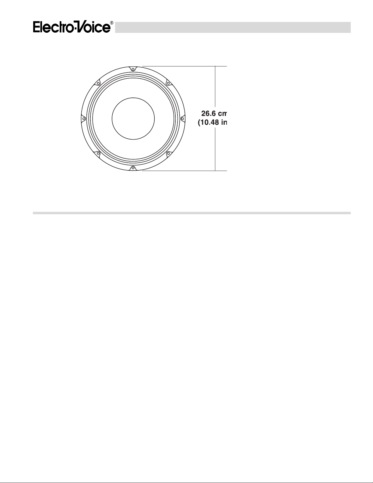
Mounting Information (see Mounting
section),
Bolt-Hole Diameter
(eight evenly spaced holes):
7.1 mm (0.28 in.)
Bolt Circle Diameter:
244 mm (9.62 in.)
Baffle Opening Diameter
(front or rear mounting):
229 mm (9.0 in.)
Electrical Connections (see Electrical
Connectors section),
Connector Type:
Push terminals for bare wires
Polarity:
A positive voltage applied to the positive
(red) terminal produces a positive
pressure at the front of the cone
Additional Descriptive Information,
Magnet Weight:
2.2 kg (4.9 lb)
Magnet Material:
Barium ferrite
Frame:
Cast aluminum
Frame Finish:
Textured black epoxy
Plating of Steel Parts:
Bright Cadmium
Voice-Coil Material:
Aluminum
Voice-Coil Insulation:
Polyimide 220 °C rating
Voice-Coil Form:
Polyimide
Back Cover:
Black, advanced synthetic elastomer
Optional Accessories:
SMH-1 mounting hardware kit
DL10X SPECIFICATION GRAPHICS
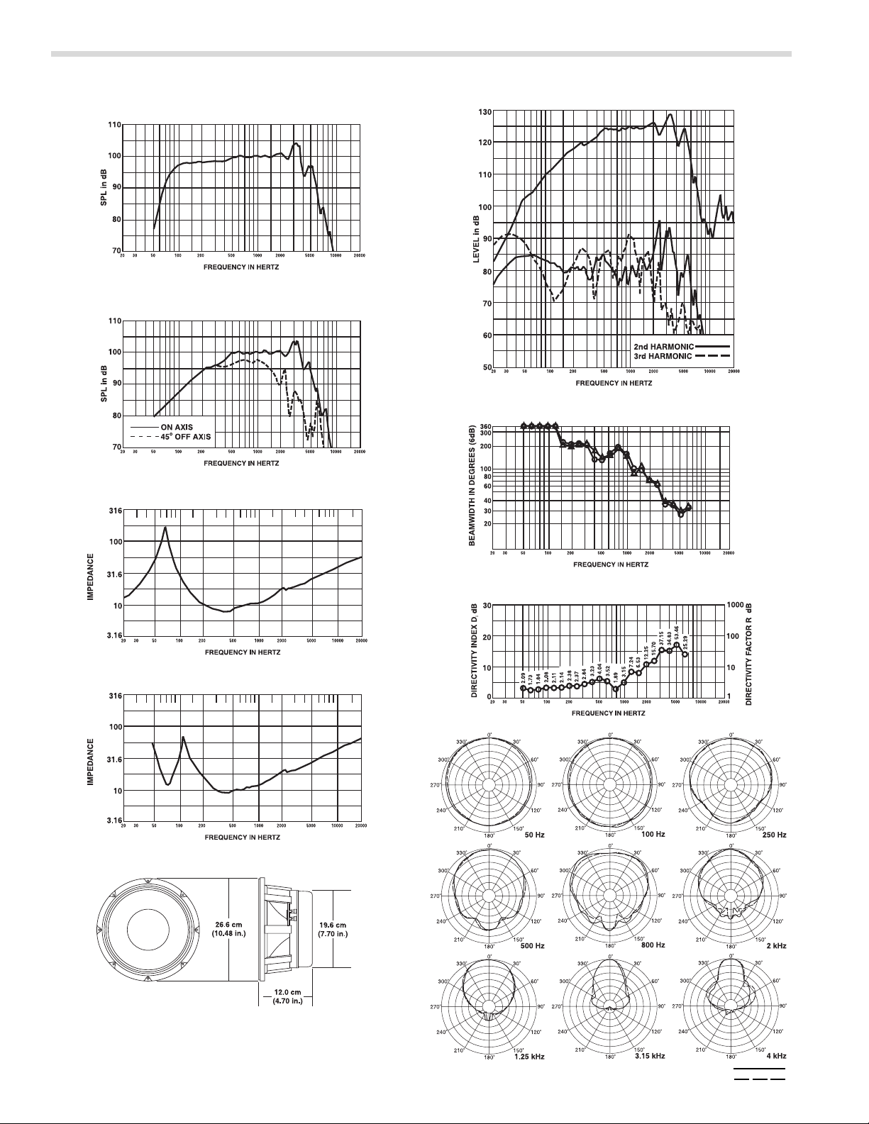
FIGURE 1 — Axial Response in Typical Enclosure
(4.0 ft3), 1 Watt/1 Meter
FIGURE 2 — Frequency Response in Standard Baffle
(0° and 45°)
FIGURE 3 — Impedance in Standard Baffle
FIGURE 6 — Distortion in Standard Baffle at 10% Rated Input Power
FIGURE 7 — Beamwidth vs. Frequency
Ω
FIGURE 4 — Impedance in Typical Enclosure (4.0 ft
Ω
FIGURE 5 — Dimensions
FIGURE 8 — Directivity vs. Frequency
θ
3
)
FIGURE 9 — Polar Response
HORIZONTAL
VERTICAL
 Loading...