

Electro-Voice Contractor Precision Series CPS4.5, Contractor Precision Series CPS8.5, Contractor Precision Series CPS.10 Owner's Manual

OWNER’S MANUAL
BEDIENUNGSANLEITUNG
preliminary

CONTRACTOR PRECISION SERIES
2
CONTENTS
Introduction . . . . . . . . . . . . . . . . . . . . . . . . . . . . . . . . . . . . . . . . . . . . . . . . . . . . . . . . . . . . . . . . . . . . 4
Unpacking and Inspection . . . . . . . . . . . . . . . . . . . . . . . . . . . . . . . . . . . . . . . . . . . . . . . . . . . . . . . 4
Scope of Delivery and Warranty . . . . . . . . . . . . . . . . . . . . . . . . . . . . . . . . . . . . . . . . . . . . . . . . . . 4
Features and Description . . . . . . . . . . . . . . . . . . . . . . . . . . . . . . . . . . . . . . . . . . . . . . . . . . . . . . . 4
Responsibility of the User . . . . . . . . . . . . . . . . . . . . . . . . . . . . . . . . . . . . . . . . . . . . . . . . . . . . . . . 4
Installation . . . . . . . . . . . . . . . . . . . . . . . . . . . . . . . . . . . . . . . . . . . . . . . . . . . . . . . . . . . . . . . . . . . . . 6
Controls, Indicators and Connections . . . . . . . . . . . . . . . . . . . . . . . . . . . . . . . . . . . . . . . . . . . . . . 6
Operating Voltage . . . . . . . . . . . . . . . . . . . . . . . . . . . . . . . . . . . . . . . . . . . . . . . . . . . . . . . . . . . . . 7
Mains Switch . . . . . . . . . . . . . . . . . . . . . . . . . . . . . . . . . . . . . . . . . . . . . . . . . . . . . . . . . . . . . . . . . 7
Mounting . . . . . . . . . . . . . . . . . . . . . . . . . . . . . . . . . . . . . . . . . . . . . . . . . . . . . . . . . . . . . . . . . . . . 7
Ventilation . . . . . . . . . . . . . . . . . . . . . . . . . . . . . . . . . . . . . . . . . . . . . . . . . . . . . . . . . . . . . . . . . . . 7
Selecting the Mode Of Operation (MODE) . . . . . . . . . . . . . . . . . . . . . . . . . . . . . . . . . . . . . . . . . . 8
Selecting the Mode of Output (OUTPUT) . . . . . . . . . . . . . . . . . . . . . . . . . . . . . . . . . . . . . . . . . . . 10
Power on delay . . . . . . . . . . . . . . . . . . . . . . . . . . . . . . . . . . . . . . . . . . . . . . . . . . . . . . . . . . . . . . . 11
Audio Cabeling . . . . . . . . . . . . . . . . . . . . . . . . . . . . . . . . . . . . . . . . . . . . . . . . . . . . . . . . . . . . . . . 12
Operation . . . . . . . . . . . . . . . . . . . . . . . . . . . . . . . . . . . . . . . . . . . . . . . . . . . . . . . . . . . . . . . . . . . . . . 13
Volume Control . . . . . . . . . . . . . . . . . . . . . . . . . . . . . . . . . . . . . . . . . . . . . . . . . . . . . . . . . . . . . . . 13
Indications . . . . . . . . . . . . . . . . . . . . . . . . . . . . . . . . . . . . . . . . . . . . . . . . . . . . . . . . . . . . . . . . . . . 13
Standby Mode (POWER REMOTE) . . . . . . . . . . . . . . . . . . . . . . . . . . . . . . . . . . . . . . . . . . . . . . . 13
Options . . . . . . . . . . . . . . . . . . . . . . . . . . . . . . . . . . . . . . . . . . . . . . . . . . . . . . . . . . . . . . . . . . . . . . . 14
RCM-810 . . . . . . . . . . . . . . . . . . . . . . . . . . . . . . . . . . . . . . . . . . . . . . . . . . . . . . . . . . . . . . . . . . . . 14
INHALT
Einführung . . . . . . . . . . . . . . . . . . . . . . . . . . . . . . . . . . . . . . . . . . . . . . . . . . . . . . . . . . . . . . . . . . . . 20
Auspacken und Inspektion . . . . . . . . . . . . . . . . . . . . . . . . . . . . . . . . . . . . . . . . . . . . . . . . . . . . . . 20
Lieferumfang und Garantie . . . . . . . . . . . . . . . . . . . . . . . . . . . . . . . . . . . . . . . . . . . . . . . . . . . . . . 20
Eigenschaften & Beschreibung . . . . . . . . . . . . . . . . . . . . . . . . . . . . . . . . . . . . . . . . . . . . . . . . . . . 20
Verantwortung des Betreibers . . . . . . . . . . . . . . . . . . . . . . . . . . . . . . . . . . . . . . . . . . . . . . . . . . . . 20
Installation . . . . . . . . . . . . . . . . . . . . . . . . . . . . . . . . . . . . . . . . . . . . . . . . . . . . . . . . . . . . . . . . . . . . . 21
Bedienelemente, Anzeigen und Anschlüsse . . . . . . . . . . . . . . . . . . . . . . . . . . . . . . . . . . . . . . . . . 21
Betriebsspannung . . . . . . . . . . . . . . . . . . . . . . . . . . . . . . . . . . . . . . . . . . . . . . . . . . . . . . . . . . . . . 22
Netzschalter . . . . . . . . . . . . . . . . . . . . . . . . . . . . . . . . . . . . . . . . . . . . . . . . . . . . . . . . . . . . . . . . . 22
Einbau . . . . . . . . . . . . . . . . . . . . . . . . . . . . . . . . . . . . . . . . . . . . . . . . . . . . . . . . . . . . . . . . . . . . . . 22
Kühlung . . . . . . . . . . . . . . . . . . . . . . . . . . . . . . . . . . . . . . . . . . . . . . . . . . . . . . . . . . . . . . . . . . . . . 22
Wahl der Betriebsart (MODE) . . . . . . . . . . . . . . . . . . . . . . . . . . . . . . . . . . . . . . . . . . . . . . . . . . . . 23
Wahl des Ausgangs-Modus (OUTPUT) . . . . . . . . . . . . . . . . . . . . . . . . . . . . . . . . . . . . . . . . . . . . 25
Einschaltverzögerung . . . . . . . . . . . . . . . . . . . . . . . . . . . . . . . . . . . . . . . . . . . . . . . . . . . . . . . . . . 26
Audio Verkabelung . . . . . . . . . . . . . . . . . . . . . . . . . . . . . . . . . . . . . . . . . . . . . . . . . . . . . . . . . . . . 27
Betrieb . . . . . . . . . . . . . . . . . . . . . . . . . . . . . . . . . . . . . . . . . . . . . . . . . . . . . . . . . . . . . . . . . . . . . . . . 28
Eingangspegel-Regler . . . . . . . . . . . . . . . . . . . . . . . . . . . . . . . . . . . . . . . . . . . . . . . . . . . . . . . . . . 28
Anzeigen . . . . . . . . . . . . . . . . . . . . . . . . . . . . . . . . . . . . . . . . . . . . . . . . . . . . . . . . . . . . . . . . . . . . 28
Standby-Modus (POWER REMOTE) . . . . . . . . . . . . . . . . . . . . . . . . . . . . . . . . . . . . . . . . . . . . . . 28
Optionen . . . . . . . . . . . . . . . . . . . . . . . . . . . . . . . . . . . . . . . . . . . . . . . . . . . . . . . . . . . . . . . . . . . . . . 29
RCM-810 . . . . . . . . . . . . . . . . . . . . . . . . . . . . . . . . . . . . . . . . . . . . . . . . . . . . . . . . . . . . . . . . . . . . 29
Specifications/Technische Daten . . . . . . . . . . . . . . . . . . . . . . . . . . . . . . . . . . . . . . . . . . . . . . . . . . 32
CPS4.5 . . . . . . . . . . . . . . . . . . . . . . . . . . . . . . . . . . . . . . . . . . . . . . . . . . . . . . . . . . . . . . . . . . . . . 32
CPS4.10 . . . . . . . . . . . . . . . . . . . . . . . . . . . . . . . . . . . . . . . . . . . . . . . . . . . . . . . . . . . . . . . . . . . . 33
CPS8.5 . . . . . . . . . . . . . . . . . . . . . . . . . . . . . . . . . . . . . . . . . . . . . . . . . . . . . . . . . . . . . . . . . . . . . 34
Mains Operation & Resulting Temperature . . . . . . . . . . . . . . . . . . . . . . . . . . . . . . . . . . . . . . . . . . 35
Block Diagram / Blockschaltbild . . . . . . . . . . . . . . . . . . . . . . . . . . . . . . . . . . . . . . . . . . . . . . . . . . 37
Dimensions / Abmessungen . . . . . . . . . . . . . . . . . . . . . . . . . . . . . . . . . . . . . . . . . . . . . . . . . . . . . 38
preliminary
CONTRACTOR PRECISION SERIES
Owner’s Manual 3
IMPORTANT SAFETY INSTRUCTIONS
1. Read these instructions.
2. Keep these instructions.
3. Heed all warnings.
4. Follow all instructions.
5. Do not use this apparatus near water.
6. Clean only with a dry cloth.
7. Do not block any ventilation openings. Install in accordance with the manufacture’s instructions.
8. Do not install near heat sources such as radiators, heat registers, stoves, or other appara tus (includ ing amp lifiers) that produ ce he at.
9. Do not defeat the safety purpose of the polarized or the grounding-type p lug. A polarized plug has two blades w ith one wider than the other.
A grounding type plug has two blades and a third grounding prong. The wide blade o r the third prong are provided for your safety. If the
provided plug does not fit into your outlet, consult an electrician for replacement of the obsolete outlet.
10. Protect the power cord from being walked on or pinched particularly at plugs, conve nience recept a c les, and the point whe re they exit from
the apparatus.
11. Only use attachments/accessories specified by the manu facturer.
12. Use only with the cart, stand, tripod, bracket, or table specified by the manufacturer, or sold with the apparatus. When a cart is used, use
caution when moving the cart/apparatus combination to avoid injury from tip-over.
13. Unplug this apparatus during lightning storms or when unused for a long period of time.
14. Refer all servicing to qualified service personnel. Servicing is required when the apparatus has bee n damaged in any way, such a s powersupply cord or plug is damaged, liquid has been spilled or object s have fallen into the app aratus, the ap paratus ha s been exposed to rain or
moisture, does not operate normally, or has been dropped.
15. Do not expose this equipment to dripping or splashing and ensure that no objects filled with liquids, such as vases, are placed on the
equipment.
16. To completely disconnect this equipment from the AC Mains, disconnect the power supply cord plug from the AC rece pt a cle.
17. The mains plug of the power supply cord shall remain readily operable.
18. No naked flame sources, such as lighted candles, should be placed on the app ara tus.
19. This is an CLASS I apparatus and shall be connected to a main socket outlet with a protective earth connection.
IMPORTANT SERVICE INSTRUCTIONS
CAUTION: These servicing instructions are for use by qualified personnel only. To reduce the risk of electric shock, do not perform any
servicing other than that contained in the Operating Instructions unless you are qualified to do so. Refer all servicing to qualified
service personnel.
1. Security regulations as stated in the EN 60065 (VDE 0860 / IEC 65) and the CSA E65 - 94 h ave to be obeyed wh en servicing the appliance.
2. Use of a mains separator transformer is mandatory during main tenance while the appliance is opened, needs to be operated and is
connected to the mains.
3. Switch off the power before retrofitting any extensions, changing the mains voltage or the outpu t voltage .
4. The minimum distance between part s car rying mains volt a ge a nd an y acce ssible me t a l piece (m e t a l enclosure) , respectively between the
mains poles has to be 3 mm and needs to be minded at all times. The minimum distance between parts carrying mains voltage and any
switches or breakers that are not connected to the mains (secondary part s) h as to be 6 mm and needs to be minded at all times.
5. Replacing special components that are marked in the circuit diagram usin g the secu rity symb ol (Note) is only perm issible w he n using
original parts.
6. Altering the circuitry without prior consent or advice is not legitimate.
7. Any work security regulations that are applicable at the locations where the appliance is being serviced have to be strictly obeyed. This
applies also to any regulations about the work place itself.
8. All instructions concerning the handling of MOS-circuits have to be observed.
The lightning flash with arrowhead symbol, within
an equilateral triangle is intended to alert the user
to the presence of uninsulated “dangerous voltage“ within the product’s enclosure that may be
of sufficent magnitude to constitute a risk of electric shock to persons.
The exclamation point within an equilateral triangle is intended to alert the user to the presence
of important operating and maintenance (servicing) instructions in the literature accompanying
the product.
Management of WEEE (waste electrical and electronic equipment) (applicable in Member States of the European Union and other European countries with individual national policies on the management of WEEE) The
symbol on the product or on its packaging indicates that this product may not be treated as regular household
waste, but has to be disposed through returning it at a Telex dealer.
NOTE: SAFETY COMPONENT (MUST BE REPLACED BY ORIGINAL PART)
preliminary

CONTRACTOR PRECISION SERIES
4 Owner‘s Manual
1 Introduction
Electro-Voice‘s new high efficient CONTRACTOR PRECISION SERIES power amps combine uncompromising audio
performance with highest reliabilty.
1.1 Unpacking and Inspection
Carefully open the packaging and take out the power amplifier. Inspect the power amp’s enclosure for damages that might
have happened during transportation. Each amplifier is examined and tested in detail before leaving the manufacturing site to
ensure that it arrives in perfect condition at your place. Please inform the transport company immediately, if the power
amplifier shows any damage. Being the addressee, you are the only person who can claim damages in transit. Keep the
cardboard box and all packaging materials for inspection by the transport company.
Keeping the cardboard box including all packing materials is also recommended, if the power amplifier shows no external
damages.
When shipping the power amp, make sure to always use its original box and packaging materials. Packing the power amplifier
like it was packed by the manufacturer guarantees optimum protection from transport damage.
1.2 Scope of Delivery and Warranty
• 1 Power Amplifier
• 1 Owner‘s Manual (this document)
• 1 Mains Cord
• 1 (CPS4.5/4.10) or 2 (CPS 8.5) Output connectors, 8 pole
• 2 (CPS4.5/4.10) or 4 (CPS 8.5) Input connectors, 6 pole
• 1 Power Remote connector, 2 pole
• 4 Foot Stands
• 1 Warranty Certificate
Keep the original invoice that states the purchase/delivery date together with the warranty certificate at a safe place.
1.3 Features and Description
The power amp CPS4.5/CPS4.10/CPS8.5 is part of Electro-Voice‘s new CONTRACTOR PRECISION SERIES, which marks
another milestone in the design and production of high-performance power amplifiers. The innovative Class H Topology offers
very high and stable output with high efficiency on an high performance level. CPS power ams are ideal for permanent
installation applications. The gapless protection circuitry concept not only prevents the power amp itself but also the
connected loudspeaker systems from being damaged. These extensive protections include Dynamic Audio Limiters, DC/HFProtections, Back-EMF-Protection, Inrush Current Limiter, Short Circuit Protection and of course Thermal Overload
Protection. The soft-start function prevents current inrush peaks on the mains, which in addition prevents the mains line
protection switch from activating during power-on operation of the power amplifier. The loudspeaker outputs are activated via
relay switching with a delay of approximately 2 seconds effectively attenuating eventual power-on noise.
1.4 Responsibility of the User
Speaker System Damage
CPS power amps provide extremely high power output that might be dangerous for human beings as well as for the
connected speaker systems. High output voltages can damage or even destroy the connected speaker systems, especially,
when the CPS amplifier is operated in bridged mode. Prior to connecting any loudspeakers, make sure to check the speaker
system’s specifications for continuous and peak power handling capacities. Even if amplification has been reduced through
lowering the input level controls on the amplifier’s front panel, it is still possible to achieve full power output with a sufficiently
high input signal.
Danger at the Loudspeaker/Power Outputs
CPS amplifiers are capable of producing dangerously high voltage output that is present at the output connectors. To protect
yourself from electric shock, do not touch any blank speaker cables during operation of the power amp.
CAUTION:
Do not ship the power amp in any other but its original packaging.
preliminary

CONTRACTOR PRECISION SERIES
Owner‘s Manual 5
HF-Interference (FCC Information USA)
1. IMPORTANT: Do not modify this unit! Changes or modifications not expressly approved by the manufacturer could void the
user‘s authority, granted by the FCC, to operate the equipment.
2. NOTE:This equipment has been tested and found to comply with the limits for a Class A digital device, pursuant to Part 15
of the FCC Rules. These limits are designed to provide reasonable protection agains harmful interference in a residential
installation. This equipment generates, uses and can radiate radio frequency energy and, if not installed and used in
accordance with the instructions, may cause harmful interference to radio communications. However, there is no guarantee
that interference will not occur in a particular installation. If this equipment does cause harmful interference to radio or
television reception, which can be determined by turning the equipment off and on, the user is encouraged to try to correct the
interference by one or more of the following measures:
• Reorient or relocate the receiving antenna
• Increase the separation between the equipment and receiver
• Connect the equipment into an outlet on a circuit different from that to which the receiver is connected
• Consult the dealer or an experienced radio/TV technician for help
This Class A digital apparatus complies with Canadian ICES-003.
Cat appareil numérique de la classe A est conforme à la norme NMB-003 du Canada.
WARNING:
The terminals marked with are hazardous live and the external wiring connected to these
terminals requires installation by an instructed person or the use of ready-made leads of
cords.
This is a Class A product. In a domestic environment this product may cause radio interferences in which case the user may be required to take adequate measures.
preliminary
CONTRACTOR PRECISION SERIES
6 Owner‘s Manual
2 Installation
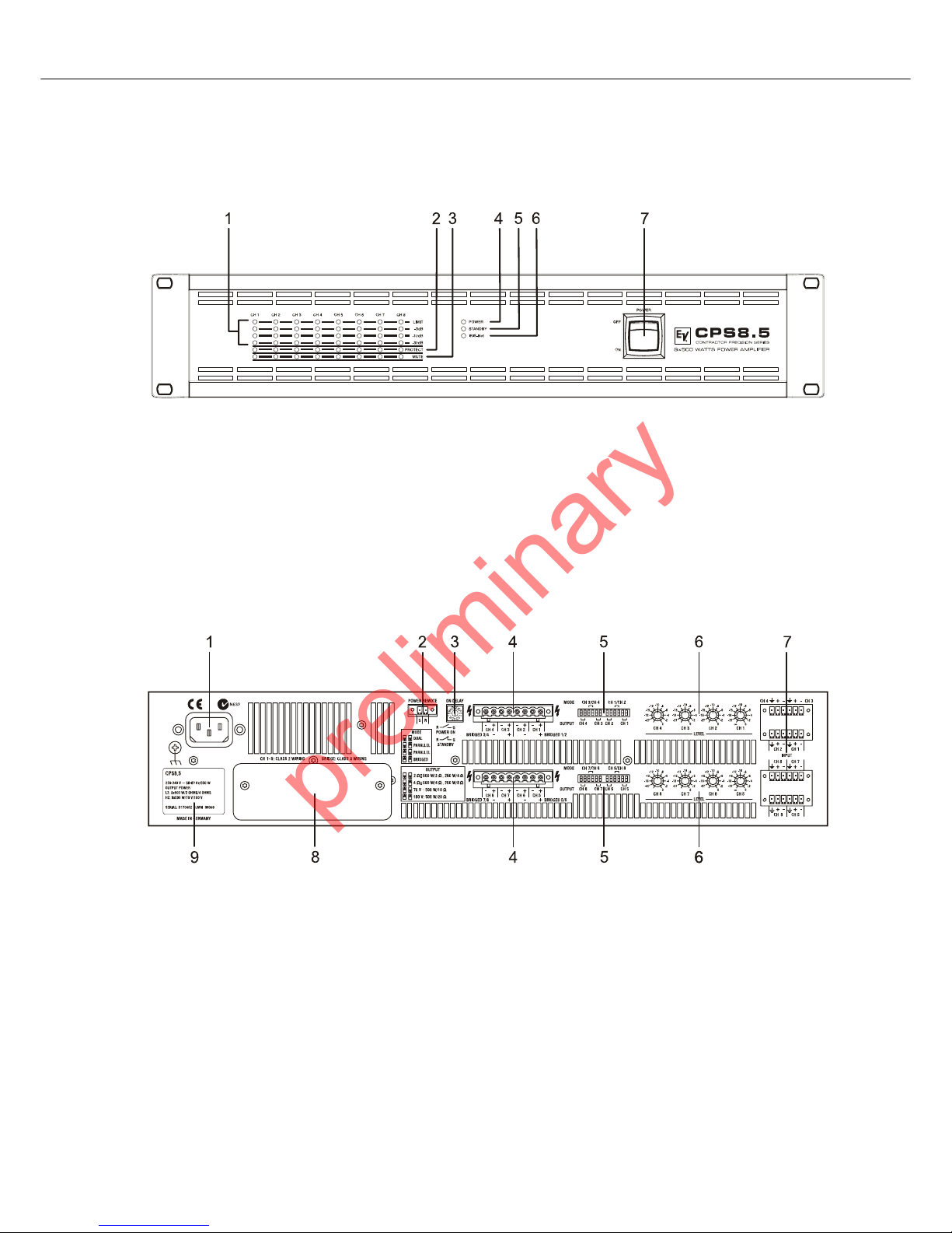
2.1 Controls, Indicators and Connections
Front View
Rear View
1 Level Indicators for each channel
2 Protections Indicator (PROTECT) for each channel
3 Muting Indicator (MUTE) for each channel
4 Power On/Off Indicator (POWER)
5 Standby Indicator (STANDBY)
6 Remote Amplifier Indicator (IRIS-Net)
7 Mains Switch
1 Mains Input
2 POWER REMOTE connector (POWER REMOTE)
3 Power On Delay selection switch (ON DELAY)
4 Power Amps Outputs (CH 1...n, BRIDGED)
5 Power Amp Outputs Mode Switch (MODE) and Outputs Load Switch (OUTPUT)
6 Input Level Control (LEVEL) for each channel
7 Audio Inputs (INPUT) for each channel
8 Expansion Slot
9 Type Plate
preliminary
CONTRACTOR PRECISION SERIES
Owner‘s Manual 7
2.2 Operating Voltage
The power amplifier receives its power supply via the MAINS IN connector. During installation, always separate the power
amplifier from the mains. Connect the power amplifier only to a mains network, which corresponds to the requirements
indicated on the type plate.
Mains Operation & Resulting Temperature
The power drawn from the mains network is converted into output power to feed the connected loudspeaker systems and into
heat. The difference between power consumption and dispensed power is called power dissipation (P
d
). The amount of heat
resulting from power dissipation might remain inside of a rack-shelf and needs to be diverted using appropriate measures.
The tables on page 35 allow the determination of power supply and cabling requirements. The tables are meant as auxiliary
means for calculating temperatures inside of a rack-shelf system/cabinet and the ventilation efforts necessary.
The column P
d
lists the leakage power in relation to different operational states. The column BTU/hr lists the dispensed heat
amount per hour. The following factors allow direct proportional calculation of the mains current I
mains
for different mains
supply voltages: 100 V = 2.3, 120 V = 1.9, 220 V = 1.05, 240 V = 0.97.
2.3 Mains Switch
The Mains Switch on the front panel separates the power amp from the mains. Turning
the Mains Switch to ON starts booting up the power amp. A soft start circuit compensates
mains inrush current peaks and thus prevents the automatic cutout of the mains from
reacting when switching on the power amplifier. Speaker system switch-on is delayed by
approximately 4 seconds, effectively suppressing any possible power-on noise, which
otherwise might be heard through the loudspeakers.
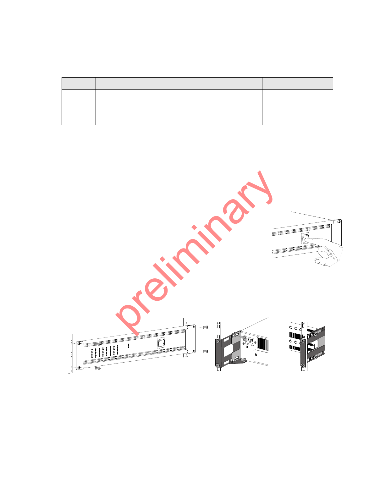
2.4 Mounting
CPS amplifiers have been designed for installation in a conventional 19-inch rack case. Attach the power amp with its frontal
rack mount ears using 4 screws and washers as shown in following illustration. Additionally securing the amplifier at the rear
becomes necessary, if the rack case in which the power amplifier has been installed will be transported. Failure to do so may
result in damage to the power amplifier as well as to the rack case. Attach the power amp as shown in the illustration using 4
case nuts and screws. Brackets for securing the power amplifier are available as accessories.
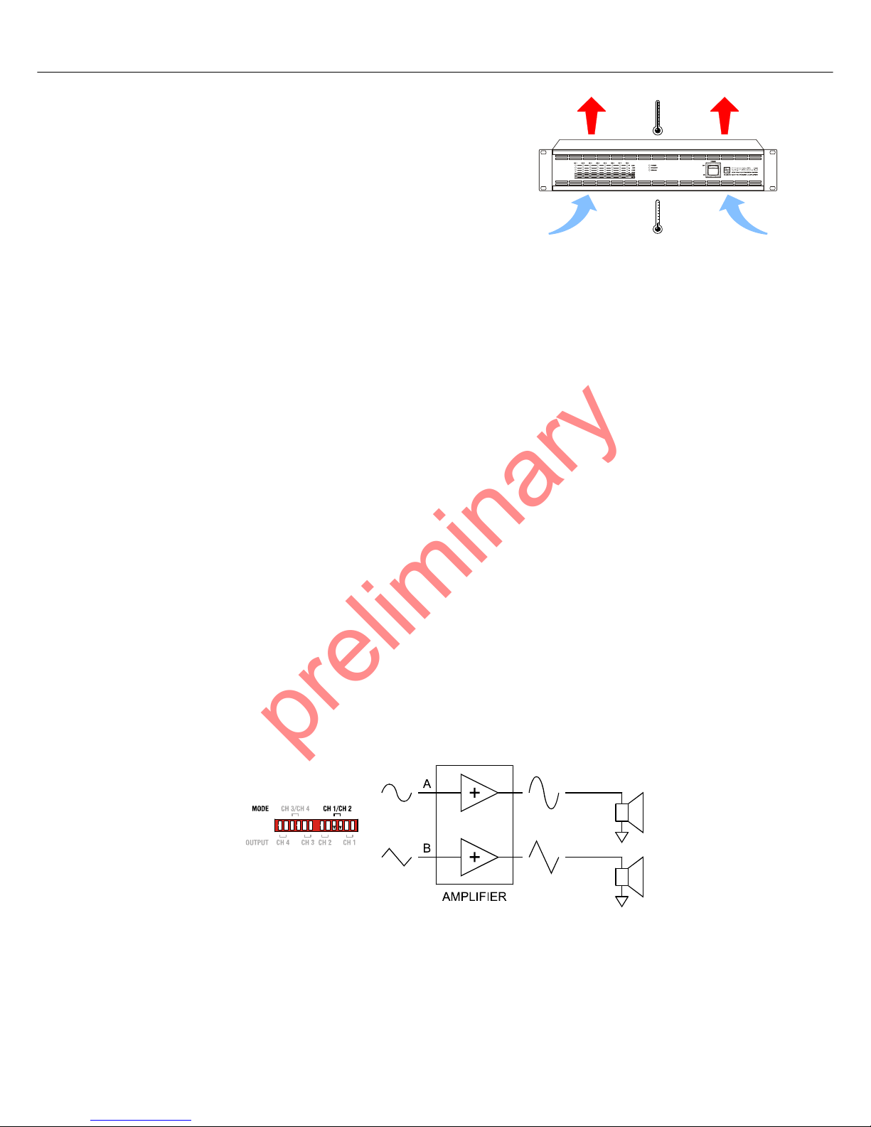
2.5 Ventilation
As with all Electro-Voice power amps with fan cooling, the airflow direction is front-to-rear, obviously because there is more
cold air outside of the rack case than inside. The power amplifier remains cooler and dissipating the developing waste heat in
a specific direction gets easier. In general, setting up or mounting the power amplifier has to be done in a way that fresh air
can enter unhindered at the front and exhausted air can exit at the rear. When installing the power amp in a case or rack
system, attention should be paid to these details to provide sufficient ventilation. Allow for an air duct of at least 60 mm x 330
mm between the rear panel of the power amplifier and the inner wall of the cabinet/rack case. Make sure that the duct reaches
up to the cabinet’s or the rack case’s top ventilation louvers. Leave room of at least 100 mm above the cabinet/rack case for
Device Vol tage Frequency Power Consumption
CPS4.5 220-240 V AC / 120 V AC / 100 V AC 50-60 Hz 490 W
CPS4.10 220-240 V AC / 120 V AC / 100 V AC 50-60 Hz 840 W
CPS8.5 220-240 V AC / 120 V AC / 100 V AC 50-60 Hz 930 W
Table 2.1: Operating Voltage
preliminary
CONTRACTOR PRECISION SERIES
8 Owner‘s Manual
ventilation. Since temperatures inside of the cabinet/rack case can easily rise
up to 40 °C during operation of the power amp, it is mandatory to bear in mind
the maximum allowable ambient temperature for all other appliances installed
in the same cabinet/rack case.
For fixed amplifier installations in a device control room that incorporate a central air-cooling system or air conditioners,
calculating the maximum heat emission may be necessary. Please also take notice of the information on page 7.
Fan Cooling
The power amplifier has two fans. The fans are temperature controlled, i.e. they are not running permanently but the running
speed of the fans is controlled depending on the ambient temperature. That in return ensures very silent running during idle
state.
The temperatures of the power ams‘s channels are registered and monitored separately.
2.6 Selecting the Mode Of Operation (MODE)
The MODE switch on the power amp‘s rear panel defines how the audio inputs handle the input signals. The amplifier types
CPS 4.5 and CPS 4.10 allow the configuration of audio inputs CH 1/CH 2 or CH 3/CH 4, the amplifier type CPS 8.5
additionally allows configuration of audio CH 5/CH 6 or CH 7/CH 8.
In the following description of the modes DUAL, PARALLEL or BRIDGED the generic letters A and B are used for the two
audio inputs of a MODE switch (example: for switch CH 1/CH 2 input A corresponds to CH 1 and input B corresponds to CH
2).
DUAL
In DUAL mode, the two channels of the power amplifier work independent from each other. This mode of operation is being
used for all 2-channel applications, like stereo or Bi-Amp (active) operation. Using the input level controls on the power amp’s
rear panel allows independently adjusting the channels’ amplification.
CAUTION:
Blocking/closing the power amp’s ventilation louvers is not permissible. Without sufficient
cooling/ventilation, the power amplifier may automatically enter protect mode. Keep ventilation louvers free from dust to ensure unhindered airflow.
Do not use the power amplifier near heat sources, like heater blowers, stoves or any other heat
radiating devices.
To ensure trouble-free operation, make certain that the maximum allowable ambient temperature of +40°C is not exceeded.
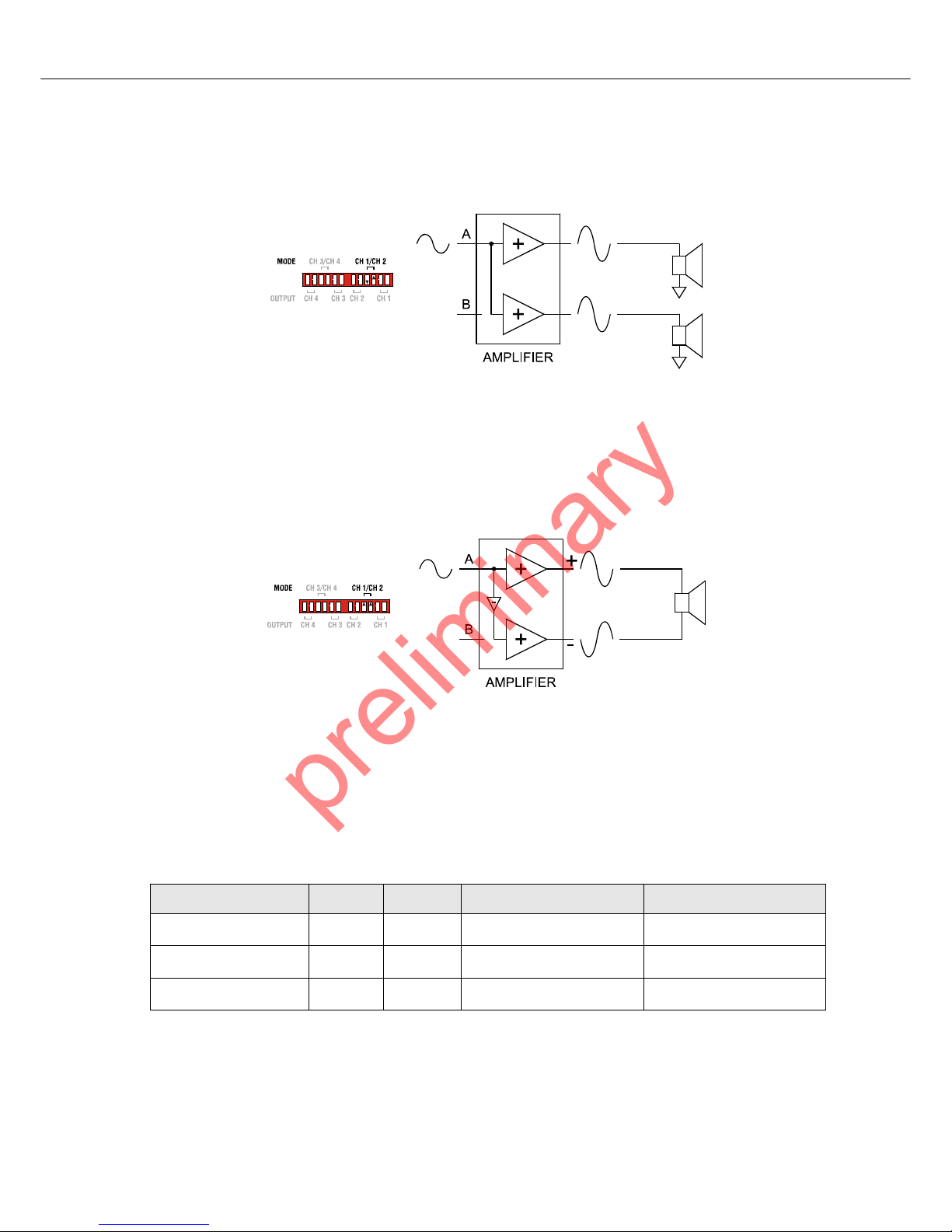
Illustration 2.1: Audio signal applied to both input connectors in DUAL mode
preliminary
CONTRACTOR PRECISION SERIES
Owner‘s Manual 9
PARALLEL
In PARALLEL mode, the inputs of channel A and channel B are directly electrically linked. The audio signal has to be applied
to the input connectors of channel A. Using the input level controls to independently control the amplification of the two
channels is still possible because only the channels’ inputs are linked. PARALLEL operation is the mode of choice, whenever
the same input signal drives multiple power amp channels of a large system installation, e.g. when driving massive bass
arrays.
BRIDGED
In BRIDGED mode both amp channels work in push-pull operation to provide doubled output voltage. The audio signal has to
be applied to the input connectors of channel A, amplification is set via input level control of channel A only. BRIDGED
operation is the mode of choice, whenever high power speakers are used.
Illustration 2.2: Audio signal applied to input A connector in PARALLEL mode
CAUTION:
In PARALLEL mode, the input signal has to be fed to input channel A only.
Illustration 2.3: Audio signal applied to input A connector in BRIDGED mode
ACHTUNG:
In BRIDGED mode operation, it is not allowable for the load connected to fall below a value of
4 ohms. Extremely high voltages can be present at the output. The connected speaker systems
must be able to handle such voltages. Make sure to completely read and fully observe power
rating specifications of the speaker systems to be used and to check them against the output
power capacity of the power amp.
OUTPUT 2 Ω 4 Ω 70 V 100 V
CPS 4.5 4 Ω 8 Ω
1000 W at 140 V (
≈20 Ω) 1000 W at 200 V (≈40 Ω)
CPS 4.10 4 Ω 8 Ω
2000 W at 140 V (
≈10 Ω) 2000 W at 200 V (≈20 Ω)
CPS 8.5 4 Ω 8 Ω
1000 W at 140 V (
≈20 Ω) 1000 W at 200 V (≈40 Ω)
Table 2.2: Minimum load in BRIDGED mode
preliminary
CONTRACTOR PRECISION SERIES
10 Owner‘s Manual
2.7 Selecting the Mode of Output (OUTPUT)
Different output modes are available for the amplifier‘s output channels. In low impedance mode (LZ) each output channel can
drive up to 4 loudspeakers. Each channel can be switched to high impedance mode (HZ) for driving 70 V or 100 V
loudspeakers without output transformers (Direct Drive).
In DUAL or PARALLEL mode each output channel‘s OUTPUT setting can be independently set. In BRIDGED mode for each
pair of outputs only the setting of the channel with odd number (1, 3, 5 or 7) matters, the setting of the channel with even
number (2, 4, 6 or 8) is ignored.
Following section describes the four different OUTPUT settings of CPS amplifiers.
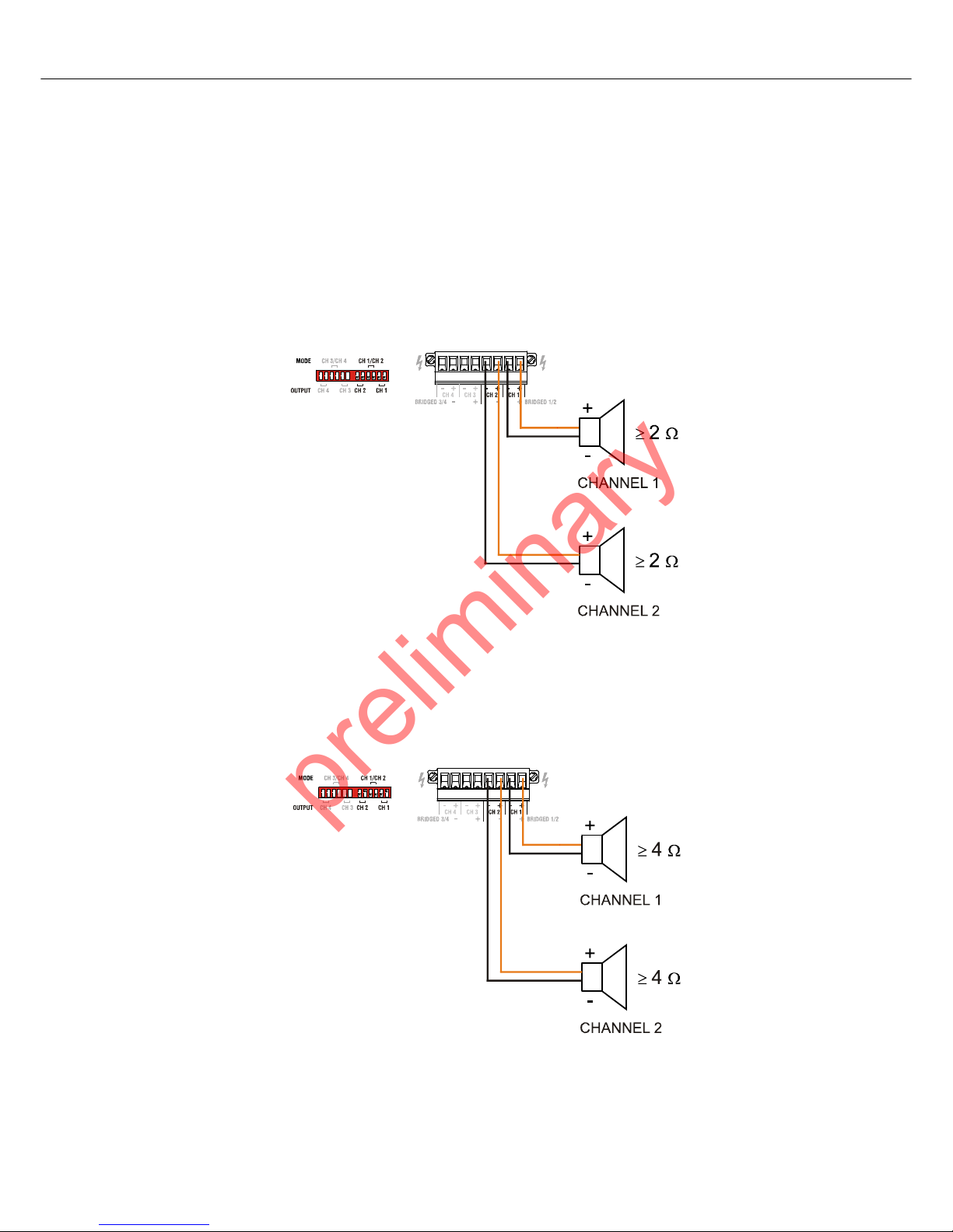
2 Ohm Mode
In 2 Ohm mode the power amplifier reaches maximum output power having a load of 2 Ω connected. Up to 4 cabinetts having
a impedance of 8 Ω each can be driven by each amplifier channel. This mode should be used if a high number of speaker with
medium or low power rating should be driven in low impedance mode (LZ).
4 Ohm Mode
In 4 Ohm mode the power amplifier reaches maximum output power having a load of 4 Ω connected. Up to 2 cabinetts having
a impedance of 8 Ω each can be driven by each amplifier channel.
This mode should be used if speakers with high power rating (e.g. Subwoofers) should be driven in low impedance mode
(LZ).
Illustration 2.4: DUAL mode of CH 1 and CH 2 in 2 Ohm Mode
Illustration 2.5: DUAL mode of CH 1 and CH 2 in 4 Ohm Mode
preliminary
CONTRACTOR PRECISION SERIES
Owner‘s Manual 11
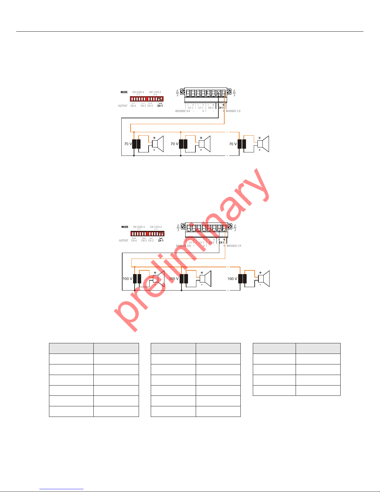
70 V Mode
The 70 V mode allows connection of 70 V loudspeaker lines (Direct Drive) in high impedance mode (HZ) without using output
transformers. In this case the maximum number of loudspeakers connected to an output channel is only limited by the
amplifier‘s output power (500 W for CPS4.5/8.5 or 1000 W for CPS4.10). This mode should be used if the distance between
amplifier and speaker is larger than 50 metres (approx. 150 feet) and/or a high number of small speakers (e.g. ceiling
speakers) is used.
100 V Mode
The 100 V mode allows connection of 100 V loudspeaker lines (Direct Drive) in high impedance mode (HZ) without using
output transformers. In this case the maximum number of loudspeakers connected to an output channel is only limited by the
amplifier‘s output power (500 W for CPS4.5/8.5 or 1000 W for CPS4.10). This mode should be used if the distance between
amplifier and speaker is larger than 50 metres (approx. 150 feet) and/or a high number of small speakers (e.g. ceiling
speakers) is used.
2.8 Power on delay
The ON DELAYswitch at the amplifier rear panel allows selecting the power on delay time. Following table shows possible
switch settings and corresponding delay times in seconds.
Illustration 2.6: CH 1 in 70 V mode
Illustration 2.7: CH 1 in 100 V mode
ON DELAY Delay time ON DELAY Delay time ON DELAY Delay time
00 60.9 C1.8
1 0.15 7 1.05 D 1.95
2 0.3 8 1.2 E 2.1
3 0.45 9 1.35 F 2.25
40.6 A1.5
50.75 B1.65
CAUTION: The setting of ON DELAY is ignored if a Remote Control Module is assembled.
preliminary
CONTRACTOR PRECISION SERIES
12 Owner‘s Manual
2.9 Audio Cabeling
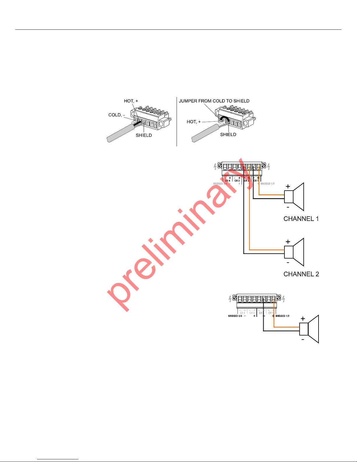
Input
Inputs are electronically balanced. Whenever possible, using balanced audio signal feeds at the input of the power amplifier is
always preferred. Unbalanced connections should only be used if the cables are very short and no interfering signals are to be
expected in the vicinity of the power amplifier. In this case, bridging the screen (shielding) and the pin of the inverting input
inside of the connector is mandatory. Otherwise, a 6 dB drop in level could result. Please also see illustration 2.9. Due to their
immunity against external interference sources, such as dimmers, mains connections, HF-control lines, etc., using balanced
cabling and connections is always preferable.
Output in DUAL Mode or PARALLEL Mode
See illustration right for connecting speakers in DUAL or PARALLEL
mode. Only connection of CH 1 and CH 2 is shown, the other channels
have to be connected identically.
The correct connection is also indicated at the amplifiers rear panel.
Output in BRIDGED Mode
See illustration right for connecting speakers in BRIDGED mode. Only connection
at CH 1/CH 2 is shown, the other channels have to be connected identically.
The correct connection is also indicated at the amplifiers rear panel.
Illustration 2.8: Balanced / unbalanced connection of input
CAUTION:
In BRIDGED mode operation, it is not allowable for the load connected to fall below the values
given in table 2.4 on page 9. Extremely high voltages can be present at the output. The connected speaker systems must be able to handle such voltages. Make sure to completely read
and fully observe power rating specifications of the speaker systems to be used and to check
them against the output power capacity of the power amp.
preliminary
 Loading...