

Page 1

TELEX COMMUNICATIONS, INC. 12000 Portland Ave. South, Burnsville, MN 55337
R
In struc tion Sheet
Gen eral De scrip tion
The APD4+ Am pli fied An tenna Split ter makes it
pos si ble to op er ate four UHF wire less di ver sity
mi cro phone re ceiv ers on four sep a rate fre quen cies us ing only two an ten nas.
SPEC I FI CA TIONS
APD4+
CAT. NO. 301614000 600-780 MHz
CAT. NO. 301614011 780-900 MHz
AMPLIFIED UHF
ANTENNA SPLITTER
It also fea tures a high de gree of out put iso la tion;
a ne ces sity in multi-fre quency sys tems to pre vent
intermodulation.
The APD4+ Split ter is com pat i ble with Elec tro-Voice and Telex UHF di ver sity wire less re ceiv ers.
PN 804035
Fre quency Range 301614000.................................................................................600-780 MHz
301614011.................................................................................780-900 MHz
3rd Or der In ter cept Out put...........................................................................greater than 18 dbm
Net Gain ............................................................................................................greater than 2 dB
Noise Fig ure ...........................................................................................................less than 3 dB
Out put Iso la tion...............................................................................................greater than 20 dB
Con nec tors, An tenna..........................................................................Stan dard TNC re cep ta cles
Power Re quire ments ................................................................................ 100-240VAC 50/60Hz
Fea tures
The APD4+ is equipped with TNC type con nec tors. Low loss co ax ial ca bles are also sup plied
for split ter to re ceiver an tenna jack con nec tions.
The APD4+ has an in ter nal power sup ply. Power
out jacks and ca bles are pro vided to sup ply up
to four re ceiv ers thus elim i nat ing ex cess power
sup ply clut ter.
Rack panel mount ing “ears” al low the APD4+ to
be mounted in a stan dard 19 inch equip ment
rack. “Knock outs” in the ears al low front con nec tion of an tenna ca bles.
-1-
Page 2
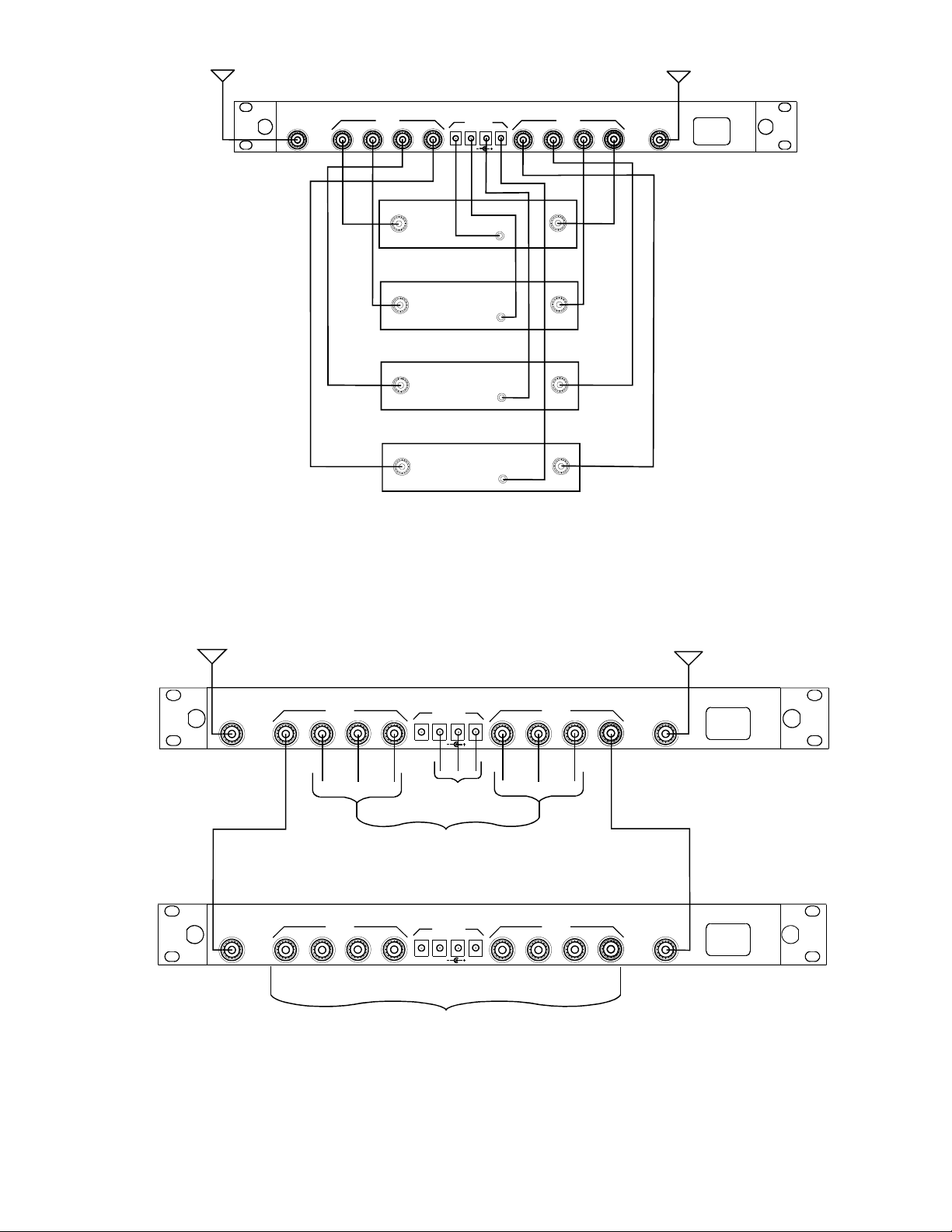
Sys tem Con fig u ra tion
Fig ure 2 il lus trates the typ i cal sys tem con fig u ra
tion us ing the APD4+.
Fig ure 3 il lus trates an ar range ment where two
split ters have been cas caded. By con nect ing one
of the out puts of the first split ter to the an tenna
in puts of the sec ond split ter, three ad di tional re ceiv ers may be driven by a sin gle pair of an ten nas.
-
SPE CIAL NOTE: In any sys tem, un used split
ter out puts should be ter mi nated with a 50 ohm
“dummy load”. See the ac ces so ries list ing at the
end of this man ual
-
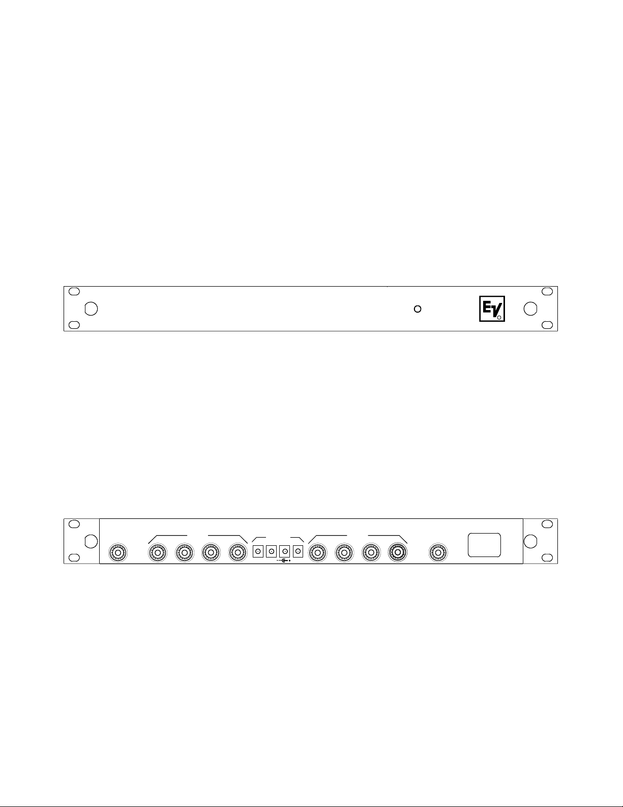
INPUT A
1 2 3 4
OUTPUT A
Front View
POWER OUT
1 2 3 4
15 VDC
1 2 3 4
OUTPUT B
APD4
Antenna/Power
Distribution System
INPUT B
+
RPOWER
90-260 VAC 50-60 Hz
POWER
Rear View
Fig ure 1
Front and Rear View
-2-
Page 3
INPUT A
OUTPUT A
1 2
3
4
RECEIVER 1
RECEIVER 2
RECEIVER 3
RECEIVER 4
1 2 3 4
Fig ure 2
Sys tem Con fig u ra tion
POWER OUT
15 VDC
1 2
OUTPUT B
90-260 VAC 50-60 Hz
3
INPUT B
4
POWER
ANTENNA
INPUT A
INPUT A
OUTPUT A
1 2 3 4
1 2
POWER OUT
15 VDC
1 2 3 4
3
4
TO RECEIVERS
ONLY
TO RECEIVERS
OR SPLITTERS
OUTPUT A
1 2 3 4
1 2
POWER OUT
15 VDC
1 2 3 4
3
4
TO RECEIVERS ONLY
(DO NOT FEED SPLITTERS FROM SECONDARY UNITS)
OUTPUT B
OUTPUT B
ANTENNA
90-260 VAC 50-60 Hz
INPUT B
POWER
90-260 VAC 50-60 Hz
INPUT B
POWER
Fig ure 3
Cas cading
-3-
Page 4

An tenna Re quire ments
The APD4+ may be used with a va ri ety of an ten nas. For best re sults, use a pair of LPA-500
di rec tional log pe ri odic an ten nas. See Fig ure 4.
The LPA-500 of fers the best per for mance and
broad est band width avail able.
R
LPA-500
THIS END TOWARD TRANSMITTER
Good re sults may be ob tained with op tional
CLA or FA-500 1/2 wave an ten nas.
The 1/4-wave an ten nas that are sup plied with
EV wire less sys tems will pro vide ad e quate per for mance in some sit u a tions. The 1/4-wave an ten nas should be ori ented as shown in Fig ure 5.
Do not use 1/4-wave an ten nas for re mote
mount ing.
LPA-500
1/2 Wave An tenna
An tennas
An tenna Place ment
If an ten nas are mounted di rectly to the APD4+,
they should be con fig ured as shown in Fig ure 5.
INPUT A
OUTPUT A
1 2 3 4
POWER OUT
1 2 3 4
15 VDC
CLA
Fig ure 4
Do not rack mount the APD4+ in this con fig u ra tion. Se ri ous loss of range and per for mance may oc cur.
Place the APD4+ with an ten nas in a lo ca tion
that is in di rect view of the trans mit ters for best
re sults.
OUTPUT B
1 2 3 4
FA-500
1/2 Wave An tenna
90-260 VAC 50-60 Hz
INPUT B
POWER
Fig ure 5
1/2 Wave An tenna Mount ing
-4-
Page 5

An tenna Place ment for Op ti mum Range
and Rack Mount ing
For max i mum range and when rack mount ing,
the an ten nas must be re motely lo cated.
The LPA-500 co mes com plete with a va ri ety of
mount ing hard ware and 10 feet (3 me ters) of
low loss co ax ial ca ble. A com bi na tion mount ing
bracket (Model No. AB-2) with 10 feet of co ax ial ca ble is avail able for 1/2 wave an ten nas.
An ten nas should be placed in a lo ca tion with a
clear “sig nal path” to the trans mit ter. This
“path” should be as short and free of ob struc tions as pos si ble. Ob struc tions, such as walls
ceil ings, and metal ob jects, will re duce range
and per for mance.
Rack Mount ing
In sert the unit into a 19" rack en clo sure and se cure with screws (not sup plied).
Rack Mounted An tenna Con nec tors
An tenna ca ble con nec tions may be made to the
front of the rack mounted APD4+ by in stall ing
the adap tor ca bles sup plied. Pro ceed as fol lows:
Re move the plug “knock outs” from the
·
front panel. See Fig ure 6.
In stall the adap tor ca bles from the back side
·
of the bracket.
Tighten the nut and lockwasher se curely.
·
At tach the other end of the ca bles to the in -
·
puts of the APD4+. Tighten se curely.
Front of rack an tenna con nec tors were de signed to al low eas ier hook up of an tenna
ca bles. We do not rec om mend mount ing
an ten nas di rectly to the con nec tors since
per for mance may be de graded.
Coax Ca ble
For best re sults, it is rec om mended that ca ble
losses be kept un der 4 dB. (Ev ery 3 dB of sig nal
loss re sults in a sys tem op er at ing dis tance re duc tion of 25%.
See the ac ces so ries sec tion of this man ual for
spe cial low loss ca ble as sem blies.
REMOVE PLUG
Fig ure 6
An tenna Con nec tors
-5-
Page 6

12 Volt Power On "An tenna In" Jacks
To power UAA-500 in-line an tenna am pli fi ers,
12 volt power is avail able on the cen ter pin of
the antenna in jacks. This power is dis abled
when the UAD4 leaves the fac tory but may be
turned on by the in staller.
To turn on the 12 volts, first take off the cover
of the split ter by re mov ing the screws. The
Jumper is in stalled on one pin of the header at
the fac tory. To turn on power, un plug the
jumper and in stall it on both pins of the header.
See Fig ure 7.
CAU TION: Do not at tach an ten nas and split ters
with a DC short cir cuit to the an tenna in jacks
when the power is turned on. Dam age could re sult to the split ter or other de vices.
The fol low ing an ten nas and ac ces so ries may be
used with power on: FA-1, CLA-X, LPA-500B,
and UAA-500.
The fol low ing an ten nas and ac ces so ries may be
used with the power off: FA-1, CLA-X, and
LPA-500.
J16 POWER ON J16 POWER OFF
J11 POWER ON
Fig ure 7
Mov ing Jumper
(Be sure to move jumper on both head ers)
J11 POWER OFF
-6-
Page 7

APD4+ Accessories and Replacement Parts
AC Power Ca bles
550024000 Eu rope
550024002 U.K.
550024013 North Amer ica
690513 Ja pan
TP-2 50 OHM/TNC dummy load
(For un used out puts on the UAD-2)
Part No. 650095
APD4+ Ca bles
Model Type Part No.
CXU-2 2 Ft. Co ax ial Cable 691459
PC-1 2 Ft. Power 690396
CXU-1 1 Ft. Co ax ial Cable 690401
(for rack ears)
Spe cial low loss an tenna ca bles with
TNC con nec tors
Model Length Or der No.
CXU-10 10 Ft. (3 me ter) 690419
R
LPA-500
THIS END TOWARD TRANSMITTER
LPA-500
450-900 MHz Log Pe ri odic An tenna
In cludes mount ing hard ware and 10 feet (3 me ter) co ax ial ca ble with TNC con nec tors
Or der No. LPA-500
Model FA-500 1/2 wave Flex i ble An tenna,
680-870 MHz
Or der No. 860031
CXU-25 25 Ft. (7.6 me ter) 71151-025
CXU-50 50 Ft. (15 me ter) 71150-075
CXU-75 75 Ft. (23 me ter) 71151-075
CXU-100 100 Ft. (30 me ter) 71151-100
UAA-500
Low noise an tenna am pli fier, 500-900 MHz
(an tenna not in cluded)
Or der No. 7186400
AB-2 Com bi na tion
An tenna Bracket and 10 foot (3 me ter) co ax ial
ca ble with TNC con nec tors. Use with FA-500
Or der No. 71138000
CLA Halfwave An tenna
CLA-1 520-565 MHz
CLA-2 565-615 MHz
CLA-3 615-660 MHz
CLA-4 660-690 MHz
CLA-5 690-725 MHz
CLA-6 725-760 MHz
CLA-8 798-865 MHz
-7-
Page 8

PRINTED IN U.S.A.
Copyright© 2004 by Telex
TELEX COMMUNICATIONS, INC.
All rights reserved
June 2004
 Loading...