

Page 1
SERVICE MANUAL
ACONE
AUDIO CONTROLLER
Page 2
IMPORTANT SAFETY INSTRUCTIONS
The lightning flash with arrowhead symbol, within an equilateral triangle is intended to alert the user to the presence
of uninsulated “dangerous voltage” within the product’s
enclosure that may be of sufficient magnitude to constitute
a risk of electric shock to persons.
The exclamation point within an equilateral triangle is
intended to alert the user to the presence of important
operating and maintance (servicing) instructions in the
literature accompanying the appliance.
1. Read these instructions.
2. Keep these instructions.
3. Heed all warnings.
4. Follow all instructions.
5. Do not use this apparatus near water.
6. Clean only with a damp cloth.
7. Do not block any of the ventilation openings.
Install in accordance with the manufactures instructions.
8. Do not install near any heat sources such as radiators, heat registers, stoves, or other apparatus that produce heat.
9. Only use attachments/accessories specified by the manufacturer.
10. Refer all servicing to qualified service personnel. Servicing is required when the apparatus has been
damaged in any way, such as power-supply cord or plug is damaged, liquid has been spilled or objects have fallen
into the apparatus, the apparatus has been exposed to rain or moisture, does not operate normally, or has
been dropped.
For US and CANADA only:
Do not defeat the safety purpose of the grounding-type plug. A grounding type plug has two blades and a third grounding prong.
The wide blade or the third prong are provided for your safety. When the provided plug does not fit into your outlet, consult an
electrican for replacement of the absolete outlet.
IMPORTANT SERVICE INSTRUCTIONS
CAUTION: These servicing instructions are for use by qualified personnel only. To reduce the
risk of electric shock, do not perform any servicing other than that contained in the
Operating Instructions unless you are qualified to do so. Refer all servicing to
qualified service personnel.
1. Security regulations as stated in the EN 60065 (VDE 0860 / IEC 65) and the CSA E65 - 94 have to be obeyed when
servicing the appliance.
2. Use of a mains separator transformer is mandatory during maintenance while the appliance is opened, needs to be
operated and is connected to the mains
3. Switch off the power before retrofitting any extensions, changing the mains voltage or the output voltage.
4. The minimum distance between parts carrying mains voltage and any accessible metal piece (metal enclosure),
respectively between the mains poles has to be 3 mm and needs to be minded at all times.
The minimum distance between parts carrying mains voltage and any switches or breakers that are not connected
to the mains (secondary parts) has to be 6 mm and needs to be minded at all times.
5. Replacing special components that are marked in the circuit diagram using the security symbol (Note) is only permissible
when using original parts.
6. Altering the circuitry without prior consent or advice is not legitimate.
7. Any work security regulations that are applicable at the location where the appliance is being serviced have to be strictly
obeyed. This applies also to any regulations about the work place itself.
8. All instructions concerning the handling of MOS - circuits have to be observed.
Note:
SAFETY COMPONENT (HAS TO BE REPLACED WITH ORIGINAL PART ONLY)
1-2
Page 3

WARRANTY (Limited)
Electro-Voice products are guaranteed against malfunction due to defects in materials or workmanship for a specified
period, as noted in the individual product-line statement(s) below, or in the individual product data sheet or owner’s
manual, beginning with the date of original purchase. If such malfunction occurs during the specified period, the
product will be repaired or replaced (at our option) without charge. The product will be returned to the customer
prepaid.
Exclusions and Limitations: The Limited Warranty does not apply to: (a) exterior finish or appearance; (b) certain
specific items described in the individual product-line statement(s) below, or in the individual product data sheet or
owner’s manual; © Malfunction resulting from use or operation of the product other than as specified in the product
data sheet or owner’s manual; (d): malfunction resulting from misuse or abuse of the product; or (e): malfunction
occurring at any time after repairs have been made to the product by anyone other than Electro-Voice or any of its
authorized service representatives.
Obtaining Warranty Service: To obtain warranty service, a customer must deliver the product, prepaid, to
Electro-Voice or any of its authorized service representatives together with proof of purchase of the product in the
form of a bill of sale or receipted invoice. A list of authorized service representatives is available from Electro-Voice
at 600 Cecil Street, Buchanan, MI 49107 (616-695-6831) and/or Electro-Voice West at 9130 Glenoaks Boulevard,
Sun Valley, CA 91532 (213-875-1900).
Incidental and Consequential Damages Excluded: Product repair or replacement and return to the customer are
the only remedies provided to the customer. Electro-Voice shall not be liable for any incidental or consequential
damages including, without limitation, injury to persons or property or loss of use. Some states do not allow the
exclusion or limitation of incidental or consequential damages so the above limitation or exclusion may not apply to
you. Other Rights: This warranty gives you specific legal rights, and you may have other rights which vary from state
to state.
Electro-Voice Electronics are guaranteed against malfunction due to defects in materials or workmanship for a
period of three (3) years from the date of original purchase. Additional details are included in the Uniform Limited
Warranty Statement.
Specifications subject to change without notice.
600 Cecil Street, Buchanan, Michigan 49107, Phone 616/695-6831, Fax: 616/695-1304
TELEX/EVI Audio Canada, 705 Progress Ave. Unit 46 Toronto, Onatario, M1H 2x1, Canada , Phone: 800/881-1685, Fax: 877/522-2242
TELEX Communications A.G., Keltenstrasse 11, CH-2563 IPSACH, Switzerland, Phone: 011-41/32-51-6833, Fax: 011-41/32-51-1221
EVI Audio Deutschland GmbH, Hirschberger Ring 45, D-94302, Straubing, Germany, Phone: 011-49/9421-7060, Fax: 011-49/9421-706265
EVI Audio France S.A., Parc de Courcerin-Allee Lech Walesa, Lognes, f-77185 Marne La Vallee, France, Phone: 011-33/1-6480-0090, Fax: 011-33/1-6006-5103
EVI Audio Japan Ltd., 2-5-60 Izumi, Suginami-ku, Tokyo, Japan 168, Phone: 011-81/3-3325-7900, Fax: 011-81/3-3325-7789
EVI Audio (Aust.) Pty., Unit 23, Block C, Slough Business Park, Slough Ave., Silverwater, N.S.W 2141, Australia, Phone 011-61/2-648-3455,
Fax: 011-61/2-648-5585
EVI Audio (Hong Kong) Limited, Unit E & F, 21 /F., Luk Hop Industrial Bldg., 8 Luk Hop St., San Po Kong, Kowloon, Hong Kong, Phone: 011-852/351-3628,
Fax: 011 -852/351-3329
(357 648 ) 12. 10 .1999
Page 4

Technische Informationen
Architects and engineers
specifications
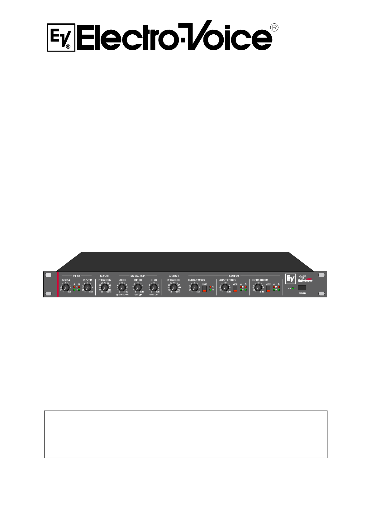
ACONE
AUDIO CONTROLLER
Beschreibung
Höchste Anforderungen an Schalldruck, Reichweite und Soundqualität
lassen sich in Audioanlagen nur mit aktiven Mehrweglautsprechersystemen realisieren bei denen die unterschiedlichen Frequenzbereiche
des Audiosignals jeweils getrennt verstärkt und wiedergegeben werden. Das vergleichsweise beste Preis-Leistungsverhältnis bieten Aktiv
2-Weganlagen mit Subwoofern. Der Bassanteil des Audiosignals wird
über die Subwoofer wiedergegeben, der Mittel-Hochtonanteil und die
Vocals über hochwertige Fullrangeboxen.
Ein wesentlicher Vorteil von Aktiv 2-Weganlagen mit Subwoofern liegt
unter anderem darin begründet, daß die Vocals nicht auf verschiedene
Lautsprechersysteme aufgeteilt sind. Dadurch ist eine problemlose
Justierung des Soundsystems möglich. Komplizierte Einmessarbeiten
sind - im Gegensatz zu aktiven 3-Weg oder 4-Wegsystemen- nicht
notwendig.
Auf kleinen Bühnen oder in kleineren Räumen kann mit einem MonoSubwoofer gearbeitet werden weil die Bässe unter derartigen Bedingungen kaum geortet werden können. Auf größeren Bühnen sind
getrennte Subwoofer für beide Seiten unerläßlich, weil sonst zu große
Lautstärkeunterschiede zwischen den Bässen und Höhen auf der
Bühne und an verschiedenen Zuhörerplätzen auftreten können. Ein
zentral angeordneter Mono-Subwoofer kann natürlich vorteilhaft als
Ergänzung eingesetzt werden.
Der AC
systeme mit Subwoofern entwickelt. Als Leistungsverstärker werden
in derartigen Systemen professionelle lineare Leistungsendstufen wie
beispielsweise Electro-Voice P1200, P2000, P3000 oder Q44, Q66
eingesetzt. Beim Einsatz von Prozessorendstufen wie beispielsweise
Electro-Voice P1250 wird der Endstufenprozessorteil einfach ausgeschaltet.
Die Installation und Bedienung des AC
problemlos, der Anwender braucht sich nicht mit der komplexen Materie von Weichenfunktionen und Entzerrern zu beschäftigen. Alle
Regler zur Anpassung an die Raumakustik und die Lautsprecherkabinette sind auf der Frontseite zugänglich, die komplizierte elektronische Verknüpfung der Einstellungen wird automatisch intern realisiert.
Die neuentwickelte PowerMax12 Weichenfunktion (Patents Pending)
nutzt Endstufenleistung und die Übertragungseigenschaften der Boxen optimal. Dadurch werden klanglich erheblich bessere Ergebnisse
mit geringerem Aufwand erzielt als mit herkömmlichen Frequenzweichen oder Controllern.
Der AC
2-Weg Instrumentalanlagen für Keyboards, Bass und Drums und
vermeidet durch die PowerMax12 Weichenfunktion den in herkömmlichen aktiven Instrumentalanlagen häufig beklagten „lack-of-punchand-definition“.
Mit dem erstklassigen Dynamikbereich von über 116dB, einem extrem
niedrigen Geräuschpegel und herausragendem Preis-Leistungsverhältnis ist der Einsatz des AC
Anwendungen in der Festinstallation eine bevorzugte Alternative zu
herkömmlichen Frequenzweichen und Controllern.
Controller wurde zum Aufbau höchstwertiger Aktiv-2-Weg-
ONE
Controllers ist vollkommen
ONE
Controller eignet sich auch exzellent zum Aufbau von Aktiv
ONE
Controllers auch in kritischen
ONE
Description
Meeting the highest requirements of modern audio applications - especially, when it comes to sound pressure level, coverage and sound
quality - is only possible when using active multi-component loudspeaker systems which provide the possibility to separately amplify and
reproduce the audio signal’s individual frequency ranges. Active 2-way
installations with additional sub woofer systems probably offer the best
price-performance ratio. The low frequency range of the audio signal is
reproduced by the sub woofers while high-quality full-range cabinets
take care of the Mid/Hi frequencies and vocals.
One of the essential advantages when using active 2-way systems with
additional sub woofers is the fact that the vocals are not divided between
several speaker systems. This, in return, offers more convenience when
adjusting the sound system. Unlike than with active 3- or 4-way configurations – difficult analyzing and measuring of sound fields is unnecessary.
Since locating low-frequency sound is merely impossible, simply using
monaural sub woofers is absolutely sufficient for smaller stages or
rooms. On wider stages it is indispensable to use individual sub woofer
systems for both sides. Otherwise, the level differences between bass
and treble would result in audible degradation of the overall sound. Of
course, adding a centrally located sub woofer might additionally improve the sound quality.
The AC
ce installations that employ active 2-way systems plus sub woofers.
Applications like these also mostly incorporate professional linear power amplifiers like the Electro-Voice P1200, P2000, P3000 or Q44, Q66.
When using processor controlled power amplifiers like the Electro-Voice
P1250, the processor section is simply switched off.
Installing and operating the AC
the user does not need to know any complex detail about crossover
functions and equalization. All controls for matching the sound to
different acoustic conditions and loudspeaker systems are located on
the front panel. Difficult tasks - like electronic signal routing and settings
for instance - are automatically carried out inside the appliance. The
newly designed PowerMax12 crossover function (patents pending)
optimally utilizes amplifier output power and loudspeaker transmission
capacities. Compared to conventional crossovers or controllers, this
results in an improved overall sound quality which is achieved with less
effort.
The AC
2-way instrument reinforcement applications for keyboards, E-bass and
drums. The PowerMax12 crossover function eliminates the often complained about “lack-of-punch-and-definition”, like it is common for conventional active musical instrument reinforcement systems.
Its excellent dynamic range of more than 116dB, the extremely low
noise level and the outstanding price-performance ratio makes the
AC
ONE
over and controller solutions – even in the critical field of permanent
installation.
Controller has been designed to be used in high-performan-
ONE
Controllers is easy as can be since
ONE
Controller is also most suitable for integration in active
ONE
Controller an advantageous alternative to conventional cross-
Page 5

Description
Satisfaire aux exigences des applications audio modernes – surtout
lorsqu’il s’agit de pression sonore, de qualité sonore et de couverture
– n’est possible qu’en utilisant des systèmes de haut-parleurs actifs
multi-voies offrant la possibilité d’amplifier et de reproduire séparément
le signal audio de chaque bande de fréquences. Les installations
actives à deux voies avec sub-woofers offrent probablement le meilleur
rapport performance-prix. Les fréquences basses du signal audio sont
reproduites par les sub-woofers alors que des enceintes large bande
de qualité se chargent des fréquences médium/hautes et des voix.
Un des avantages essentiels offert par l’utilisation des systèmes actifs
à deux voies avec des sub-woofers supplémentaires est que les voix
ne sont pas réparties sur plusieurs systèmes de haut-parleurs. Ce qui
est beaucoup plus pratique pour le réglage de la sonorisation. Contrairement aux configurations actives à 3 ou 4 voies, les mesures et
les analyses compliquées des champs sonores ne sont pas nécessaires.
Pour les scènes ou les salles de petites dimensions, comme les sons
basses fréquences sont pratiquement impossibles à situer, il suffit
d’utiliser des sub-woofers mono. Pour les scènes plus grandes il est
absolument indispensable d’utiliser un système de sub-woofers
séparés pour chaque côté. Sinon, les différences de niveau entre les
basses et les aigus provoqueront une dégradation audible du son dans
son ensemble. Bien sûr, l’ajout d’un sub-woofer placé au centre
améliorera encore la qualité sonore.
Le contrôleur AC
a été conçu pour être utilisé dans des installations
ONE
performantes employant des systèmes actifs à deux voies avec subwoofers. De telles applications incluent fréquemment des amplificateurs de puissance linéaires professionnels comme les Electro-Voice
P1200, P2000, P3000 ou Q44, Q66. Lors de l’utilisation d’amplificateurs de puissance contrôlés par processeur comme le Electro-Voice
P1250, la section processeur est tout simplement désactivée.
L’installation et le maniement des contrôleurs AC
est aussi simple
ONE
que possible, puisque l’utilisateur n’a besoin de connaître les détails
complexes des fonctions de Crossover, ou d’égalisation. Tous les
contrôles permettant d’adapter le son aux diverses conditions acoustiques et aux divers systèmes de haut-parleurs se trouvent en face
avant. Les tâches difficiles – comme l’acheminement du signal électronique et les réglages, par exemple - sont automatiquement pris en
charge en dehors de l’appareil. La fonction de Crossover, nouvellement conçue, du PowerMax12 (brevet en cours) optimise la puissance
de sortie de l’amplificateur en fonction des caractéristiques du hautparleur. Comparé aux Crossovers ou aux contrôleurs conventionnels,
le résultat est une qualité sonore globale améliorée qui est obtenue
avec moins d’efforts.
Le contrôleur AC
convient également parfaitement lorsqu’il est
ONE
intégré dans des applications actives à 2 voies pour le renforcement
d’instruments, tels les claviers, les basses et les batteries électriques.
La fonction Crossover du PowerMax12 élimine le sempiternel
”manque-de-punch-et-de-définition”, commun aux systèmes actifs
conventionnels utiliser pour le renforcement des instruments de musique.
Son excellente dynamique, de plus de 116 dB, son niveau de bruit
extrêmement bas et son rapport performance-prix très attractif font du
contrôleur AC
une alternative avantageuse aux solutions de Cross-
ONE
over et de contrôleurs conventionnels – même dans le domaine
critique des installations permanentes.
Technical Specifications AC
ONE
All level and frequency controls in center position, Lo-EQ and Hi-EQ
controls at 0dB, MID-EQ control at -4dB, unless otherwise specified.
Note: 0dBu = 0.775V
Crossover
Mode 2-Way-Stereo + SUB Mono
Frequency, sweepable 45Hz ... 160Hz
Filter Type PowerMax12*
LO-Cut
Filter Type 12dB/octave
Frequency, sweepable 20Hz ... 100Hz
Equalization
LO-EQ 50Hz, Shelving, 0dB ... +12dB
MID-EQ 4kHz, Dip, -8dB ... 0dB
HI-EQ 15kHz, Lift, 0dB ... +8dB
Inputs A, B
Type Active Balanced, XLR-female
Input Impedance 20kOhm
Maximum Level +20dBu
Rated Level +6dBu
Gain Range -∞ ... + 6dB
Parallel Outputs A, B XLR-male
Outputs HI, LO, SUB
Type Active Balanced, XLR-male
Output Impedance 75 Ohm
Maximum Level + 20dBu
Rated Level + 6dBu
Gain Range -∞ ... + 6dB
Frequency Response,
-3dB ref.1kHz, Lo-Cut 20Hz 16Hz ... 150kHz
Nominal Gain
Maximum Gain
0dB
+12dB
Dynamic Range, +20dBu, noise A-weighted 117dB
THD+N,
THD+N,
20Hz ... 20kHz, +6dBu < 0.02%
typical, +6dBu
0.003%
Crosstalk <-80dB
Mute Switch Rejection
Level Control Attenuation
> 90dB
> 80dB
Power Requirements, 50Hz....60Hz,
voltage selector 100V ... 120V, 220V ... 240V
Power Consumption
17 W
Dimensions, (WxHxD), mm 483 x 43.6 x 226.5
Weight
Optional, input transformer
3.2 kg
NRS 90208
*Patents pending
Page 6
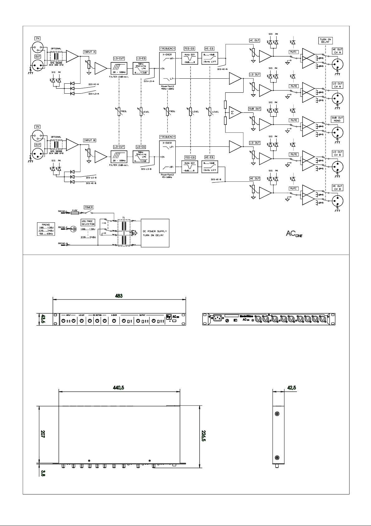
Abmessungen / Dimensions (in mm)
Page 7

WARRANTY (Limited)
Electro-Voice products are guaranteed against malfunction due to defects in materials or workmanship for a specified period, as
noted in the individual product-line statement(s) below, or in the individual product data sheet or owner’s manual, beginning with
the date of original purchase. If such malfunction occurs during the specified period, the product will be repaired or replaced (at
our option) without charge. The product will be returned to the customer prepaid.
Exclusions and Limitations: The Limited Warranty does not apply to: (a) exterior finish or appearance; (b) certain specific items
described in the individual product-line statement(s) below, or in the individual product data sheet or owner’s manual; ©
Malfunction resulting from use or operation of the product other than as specified in the product data sheet or owner’s manual;
(d): malfunction resulting from misuse or abuse of the product; or (e): malfunction occurring at any time after repairs have been
made to the product by anyone other than Electro-Voice or any of its authorized service representatives.
Obtaining Warranty Service: To obtain warranty service, a customer must deliver the product, prepaid, to Electro-Voice or any
of its authorized service representatives together with proof of purchase of the product in the form of a bill of sale or receipted
invoice. A list of authorized service representatives is available from Electro-Voice at 600 Cecil Street, Buchanan, MI 49107
(616-695-6831) and/or Electro-Voice West at 9130 Glenoaks Boulevard, Sun Valley, CA 91532 (213-875-1900).
Incidental and Consequential Damages Excluded: Product repair or replacement and return to the customer are the only
remedies provided to the customer. Electro-Voice shall not be liable for any incidental or consequential damages including,
without limitation, injury to persons or property or loss of use. Some states do not allow the exclusion or limitation of incidental
or consequential damages so the above limitation or exclusion may not apply to you. Other Rights: This warranty gives you
specific legal rights, and you may have other rights which vary from state to state.
Electro-Voice Electronics are guaranteed against malfunction due to defects in materials or workmanship for a period of three
(3) years from the date of original purchase. Additional details are included in the Uniform Limited Warranty Statement.
Specifications subject to change without notice.
600 Cecil Street, Buchanan, Michigan 49107, Phone 616/695-6831, Fax: 616/695-1304
TELEX/EVI Audio Canada, 705 Progress Ave. Unit 46 Toronto, Onatario, M1H 2x1, Canada , Phone: 800/881-1685, Fax: 877/522-2242
TELEX Communications A.G., Keltenstrasse 11, CH-2563 IPSACH, Switzerland, Phone: 011-41/32-51-6833, Fax: 011-41/32-51-1221
EVI Audio Deutschland GmbH, Hirschberger Ring 45, D-94302, Straubing, Germany, Phone: 011-49/9421-7060, Fax: 011-49/9421-706265
EVI Audio France S.A., Parc de Courcerin-Allee Lech Walesa, Lognes, f-77185 Marne La Vallee, France, Phone: 011-33/1-6480-0090, Fax: 011-33/1-6006-5103
EVI Audio Japan Ltd., 2-5-60 Izumi, Suginami-ku, Tokyo, Japan 168, Phone: 011-81/3-3325-7900, Fax: 011-81/3-3325-7789
EVI Audio (Aust.) Pty., Unit 23, Block C, Slough Business Park, Slough Ave., Silverwater, N.S.W 2141, Australia, Phone 011-61/2-648-3455,
Fax: 011-61/2-648-5585
EVI Audio (Hong Kong) Limited, Unit E & F, 21 /F., Luk Hop Industrial Bldg., 8 Luk Hop St., San Po Kong, Kowloon, Hong Kong, Phone: 011-852/351-3628,
Fax: 011 -852/351-3329
Page 8

Page 9

Page 10

MEASURED DATA ACONE
Function: Analog Controller Issue Date: 27.07. 2000
The measured data apply to the following appliances:
Unit Model Unit Number Mains Voltage Mains Frequency
ACONE
Testing Conditions:
Measuring tolerance: ∆X = ± 1.5 dB
Measuring frequency: f = 100Hz / 1 kHz / 10 kHz
Stated level values referred to: U = 775 mV ( 0 dBu)
Source impedance Line: R(Q) = 50 Ω
Load impedance Outputs: R(L) = 100 kΩ
INPUT-, EQ-, Output- Control Center position
Voltage selector switch 220 V - 240 V ( fuse T100mA )
Measurement standards: IEC 268, IHF-A
Safety class: I
Test voltage IEC65: 3000 Vrms
U(F) = Extraneous Voltage Unweighted, with B = 22Hz ... 22 kHz, effective value (IEC 268)
U(G) = Noise Voltage Weighting filter, acc. to CCIR-468-3, quasi peak weighted (IEC 268)
U(A) = Interference Voltage A-weighted, dB(A), effective value (IEC 268)
170 090 120 or 230 V 50 - 60 Hz
- The printed board assembly 82227 offers measuring points for servicing purposes.
CNS 2 Assignment
1 + 15 V
2 GND
3 - 15 V
4 + VSS
5 GND
6 - VSS
7 Relay
8 Time In
1. Operating Voltages: ACONE Europe U(B) = 230V / 50Hz ... 60 Hz
ACONE Japan U(B) = 100V / 50Hz ... 60 Hz
ACONE U.S.A. U(B) = 120V / 50Hz ... 60 Hz
ACONE Australia U(B) = 240V / 50Hz ... 60 Hz
2. Operating Voltage Deviation Range: - 10 % .... + 6 % in all modes
3. Power Consumption:
ACONE
Power Consumption
Idling 17 W
4. Settings/Adjustments:
OUTPUT STAGE SYMMETRY:
Symmetrically measure the output voltage --> U1 ( HI-OUT - 1 kHz / LO-OUT - 100 Hz )
Page: 1 / 5
Page 11

Sum the signals of XLR-Pin 2 and XLR-Pin 3 via high-quality (precise) resistors ( < 10 kΩ / < 0.5 % ) at the
input of the measuring device and adjust the resulting signal via trimmers VR 11 / VR 12 / VR 13 / VR 14 /
VR 15 to its minimum value --> U2
Unsymmetrical Attenuation = log ( U1 / U2 ) = > 35 dB
5. Function Test
POWER-ON DELAY :
Feed the signal to Input-Channel A / B and switch the appliance on using the Power-On switch.
Approximately 2 seconds after switching the appliance on, the signal is present at the output.
MUTE-SWITCH:
Feed the signal to Input-Channel A / B. Measure at the outputs and check the function of each Mute-Switch.
6. Level
-All level and frequency controls set to their center position, EQ SECTION- all controls set to their “0”position.
Input U(E) Output U(A) Comments
Channel A IN ( 1 kHz ) 0 dBu OUTPUT CH A HI 0 dBu
Channel A IN ( 1 kHz ) 0 dBu OUTPUT CH A HI +6 dBu HI OUT control at +6 dB
Channel A IN ( 1 kHz ) 0 dBu OUTPUT CH A HI +12 dBu INPUT A + HI OUT control at +6 dB
Channel A IN ( 100 Hz ) 0 dBu OUTPUT CH A LO 0 dBu
Channel A IN ( 100 Hz ) 0 dBu OUTPUT CH A LO 6 dBu LO OUT control at +6 dB
Channel A IN ( 100 Hz ) 0 dBu OUTPUT SUB MONO -3.5 dBu
Channel A IN ( 100 Hz ) 0 dBu OUTPUT SUB MONO +2.5 dBu SUB OUT control at +6 dB
Channel B IN ( 1 kHz ) 0 dBu OUTPUT CH B HI 0 dBu
Channel B IN ( 1 kHz ) 0 dBu OUTPUT CH B HI +6 dBu HI OUT control at +6 dB
Channel B IN ( 1 kHz ) 0 dBu OUTPUT CH B HI +12 dBu INPUT B + HI OUT control at +6 dB
Channel B IN ( 100 Hz ) 0 dBu OUTPUT CH B LO 0 dBu
Channel B IN ( 100 Hz ) 0 dBu OUTPUT CH B LO +6 dBu LO OUT control at +6 dB
Channel B IN ( 100 Hz ) 0 dBu OUTPUT SUB MONO -3.5 dBu
Channel B IN ( 100 Hz ) 0 dBu OUTPUT SUB MONO +2.5 dBu SUB OUT control at +6 dB
-Make sure that all level controils are set to their “∞”-position.
7. Amplitudes – Non-Linearities
- MBW = 80 kHz
- All measured values for U(A) = +6 dBu
Input Output THD+N at
100Hz
Channel A / B IN ( 1 kHz ) OUTPUTS CH A / B HI < 0.004 % < 0.015 %
Channel A / B IN ( 100 Hz ) OUTPUTS CH A / B LO < 0.005 %
Channel A / B IN ( 100 Hz ) OUTPUT SUB MONO < 0.005 %
Page: 2 / 5
THD+N at
1kHz
THD+N at
10kHz
Page 12

8.1 Frequency Response
15.000
12.000
9.0000
6.0000
3.0000
0.0
-3.000
-6.000
-9.000
-12.00
-15.00
-18.00
-21.00
LO-EQ
+12dB
+6dB
MID-EQ
10 100 1k 10k 100k
HI-EQ
+8dB
+4dB
-4dB
-8dB
8.2 LoCut 8.3 X-Over
15.00
12.00
9.00
6.00
3.00
20Hz
0.00
- 3.00
- 6.00
- 9.00
-12.00
-15.00
-18.00
-21.00
50Hz
100Hz
10 100 1k 10k 100k
15.00
12.00
9.00
6.00
3.00
0.00
-3.00
-6.00
-9.00
-12.00
-15.00
-18.00
-21.00
10 100 1k 10k 100k
160H z100Hz45Hz
9. Border Frequencies - 3 dB @ 1 kHz
- All level controls within the signal path set to fully open, EQ SECTION- all controls set to their “0”-position,
- LO-CUT set to 20 Hz, X-OVER in center position.
ACONE
Input Output f(u) f(o)
Channel A / B IN OUTPUTS CH A / B HI 76 Hz > 150 kHz
Channel A / B IN OUTPUTS CH A / B LO 16 Hz 125 Hz
Channel A / B IN OUTPUT SUB MONO 14 Hz 145 Hz
10. Noise Interference
- U(F) = extraneous voltage non-weighted with B = 22 Hz … 22 kHz, effective value (IEC 268-1)
- U(G) = noise voltage, frequency-weighting filter according to CCIR-468-3, quasi peak-weighted (IEC 268-1)
- U(A) = interference voltage A-weighted, dB(A), effective value (IEC 268-1)
- S/N ratio ref. to max. output voltage, A-weighted
Page: 3 / 5
Page 13

- All level and frequency controls set to their center position, EQ SECTION- all controls set to their “0”position
Output U(F)
dBu
HI OUT A / B -95 -84 -97 0 -117
HI OUT A / B -106 -95 -108 HI OUT STEREO controls down
HI OUT A / B -89 -78 -91 HI OUT STEREO controls up
LO OUT A / B -99 -89 -102 0 -122
LO OUT A / B -101 -90 -103 LO OUT STEREO controls down
LO OUT A / B -96 -88 -101 LO OUT STEREO controls up
SUB MONO -96 -86 -99 +2.5 -119
SUB MONO -101 -90 -103 SUB OUT MONO controls down
SUB MONO -92 -82 -95 SUB OUT MONO controls up
11. Operating Voltages and Service Measuring Points
- Voltages measured at the corresponding pin to GND ( mains voltage 230 V )
82227 Measured in
CNS 2
1 + 15 V
2 GND
3 - 15 V
4 + VSS
5 GND
6 - VSS
7 Relay - 23 after approx. 2 sec.
8 Time In - 11 V
U(G)
dBu
U(A)
dBu
Idling Condition
GAINdBS/N-R.dBComments
+ 15 V ± 2.5%
- 15 V ± 2.5%
+ 23 V ± 2%
- 23 V ± 2%
Interference and Ripple Voltage
U(F)rms
< 30 µV
< 30 µV
< 200 mV
< 200 mV
Voltage selector set to 100 - 120 V. Mains voltage adjusted to115 V via regulating transformer.
Voltage measurement at CNS 2.4 / 2.6 referred to CNS 2.5 ( ±± 23 V ).
Afterwards re-set the voltage selector to 220 – 240 V!
12. Indicators
- The LED starts lighting when the stated input voltages are applied – tolerance +/- 2 dB.
- All level and frequency controls set to their center position, EQ SECTION- all controls set to their “0”position
Indicator Input Comments U(E)
SIGNAL INPUT A / B Channel A / BIn( 10kHz ) -18 dBu
PEAK INPUT A / B Channel A / BInLO-EQ positioned at +12 dB ( 100Hz ) +11 dBu
PEAK INPUT A / B Channel A / BInHI-EQ positioned at +8 dB ( 10kHz ) +11 dBu
SIGNAL HI OUTPUT A / B Channel A / BIn( 10kHz ) -15 dBu
PEAK HI OUTPUT A / B Channel A / BIn( 10kHz ) +14 dBu
Page: 4 / 5
Page 14

SIGNAL LO OUTPUT A / B Channel A / BIn( 100Hz ) -17 dBu
PEAK LO OUTPUT A / B Channel A / BIn( 100Hz ) +14 dBu
SIGNAL SUB OUT MONO Channel A / BIn( 100Hz ) Input: CH A+B -19 dBu
PEAK SUB OUT MONO Channel A / BIn( 100Hz ) Input: CH A+B +11 dBu
13. Initial State (factory-shipped)
Unit Type Unit-No. Mains Voltage Voltage Selector/Fuse
ACONE Europe
ACONE Australia
ACONE Japan / USA
( Mains cord 346 832, Fuse 302 603, Supplement 357 602, Polyester bag 304 712 )
170 090 230 V Set to 220V - 240V / 80 mA
With mains cord 300 425
240 V Set to 220V - 240V / 80 mA
With mains cord 354 619
100 V / 120 V Set to 100V - 120V / 160 mA
With US-Kit 357 601
Page: 5 / 5
Page 15

Stücklisten - Bill of material
Pos. Nr.
Ref. No.
Best. Nr.
Z 020 345095 FUSS-GUMMI 12.7X 3.5 rubber foot
Z 040 357648 BEDIENUNGSANL. AC ONE owner's manual
Z 050 300425 KABEL-NETZ 2.0 M 10A power cable Europe
356348 DK 11 SW/GR/SW C 6FL knob
347430 TK 10X6 SW 2,8 push button black 10x6
337059 KNOPF-TASTE 12X7 SW 3.3 push button black 12x7
335228 KRT. DRP 515X365X100 carton
335229 STYROPOR-EINLAGE DRP carton filler
333375 SCHUTZHÜLLE 500X700X0,05 poly bag
357643 FB.AC ONE BED front panel ACone
357957 DEC.AC ONE BED chassis cover
822278 PCBAR#PX 230 main pcb 82227
C0001 329021 KO-KER 0.10MF 100V 20% cap ceramic 100nF
C0002 329021 KO-KER 0.10MF 100V 20% cap ceramic 100nF
C0003 301543 KO-KER 330.0PF 500V 10% cap ceramic 330pF
C0004 301543 KO-KER 330.0PF 500V 10% cap ceramic 330pF
C0005 301543 KO-KER 330.0PF 500V 10% cap ceramic 330pF
C0006 301543 KO-KER 330.0PF 500V 10% cap ceramic 330pF
C0007 301543 KO-KER 330.0PF 500V 10% cap ceramic 330pF
C0008 301543 KO-KER 330.0PF 500V 10% cap ceramic 330pF
C0009 301543 KO-KER 330.0PF 500V 10% cap ceramic 330pF
C0010 301543 KO-KER 330.0PF 500V 10% cap ceramic 330pF
C0013 301558 KO-KER 33.0PF 100V 2% cap ceramic 33pF
C0014 301558 KO-KER 33.0PF 100V 2% cap ceramic 33pF
C0015 301558 KO-KER 33.0PF 100V 2% cap ceramic 33pF
C0016 301558 KO-KER 33.0PF 100V 2% cap ceramic 33pF
C0017 343532 KO-EL 100.000MF 25V cap electrolytic 100uF/25V
C0018 343532 KO-EL 100.000MF 25V cap electrolytic 100uF/25V
C0019 301530 KO-KER 100.0PF 500V 10% cap ceramic 100pF
C0020 301530 KO-KER 100.0PF 500V 10% cap ceramic 100pF
C0021 343532 KO-EL 100.000MF 25V cap electrolytic 100uF/25V
C0022 343532 KO-EL 100.000MF 25V cap electrolytic 100uF/25V
C0023 344109 KO-FOL 0.056MF 63V 5% cap mylar 56nF
C0024 344109 KO-FOL 0.056MF 63V 5% cap mylar 56nF
C0025 340988 KO-FOL 0.470MF 63V 5% cap mylar 470nF
C0026 340988 KO-FOL 0.470MF 63V 5% cap mylar 470nF
Part No. Bezeichnung Description
170090 Acone
Zubehör Accessories
Mechanische Teile Metal work
Page 16

Pos. Nr.
Ref. No.
Best. Nr.
C0027 343532 KO-EL 100.000MF 25V cap electrolytic 100uF/25V
C0028 343532 KO-EL 100.000MF 25V cap electrolytic 100uF/25V
C0029 342923 KO-FOL 0.220MF 63V 5% cap mylar 220nF
C0030 342923 KO-FOL 0.220MF 63V 5% cap mylar 220nF
C0031 344105 KO-FOL 0.027MF 100V 5% cap mylar 27nF
C0032 344105 KO-FOL 0.027MF 100V 5% cap mylar 27nF
C0033 342923 KO-FOL 0.220MF 63V 5% cap mylar 220nF
C0034 342923 KO-FOL 0.220MF 63V 5% cap mylar 220nF
C0035 344105 KO-FOL 0.027MF 100V 5% cap mylar 27nF
C0036 344105 KO-FOL 0.027MF 100V 5% cap mylar 27nF
C0037 301543 KO-KER 330.0PF 500V 10% cap ceramic 330pF
C0038 301543 KO-KER 330.0PF 500V 10% cap ceramic 330pF
C0039 337238 KO-FOL 0.680MF 63V 5% cap mylar 680nF
C0040 337238 KO-FOL 0.680MF 63V 5% cap mylar 680nF
C0041 337238 KO-FOL 0.680MF 63V 5% cap mylar 680nF
C0042 337238 KO-FOL 0.680MF 63V 5% cap mylar 680nF
C0043 344109 KO-FOL 0.056MF 63V 5% cap mylar 56nF
C0044 344109 KO-FOL 0.056MF 63V 5% cap mylar 56nF
C0045 340988 KO-FOL 0.470MF 63V 5% cap mylar 470nF
C0046 340988 KO-FOL 0.470MF 63V 5% cap mylar 470nF
C0047 343532 KO-EL 100.000MF 25V cap electrolytic 100uF/25V
C0048 343532 KO-EL 100.000MF 25V cap electrolytic 100uF/25V
C0053 343532 KO-EL 100.000MF 25V cap electrolytic 100uF/25V
C0054 343532 KO-EL 100.000MF 25V cap electrolytic 100uF/25V
C0055 343532 KO-EL 100.000MF 25V cap electrolytic 100uF/25V
C0056 301558 KO-KER 33.0PF 100V 2% cap ceramic 33pF
C0057 301530 KO-KER 100.0PF 500V 10% cap ceramic 100pF
C0058 301530 KO-KER 100.0PF 500V 10% cap ceramic 100pF
C0059 343532 KO-EL 100.000MF 25V cap electrolytic 100uF/25V
C0060 343532 KO-EL 100.000MF 25V cap electrolytic 100uF/25V
C0061 343532 KO-EL 100.000MF 25V cap electrolytic 100uF/25V
C0062 301530 KO-KER 100.0PF 500V 10% cap ceramic 100pF
C0063 343532 KO-EL 100.000MF 25V cap electrolytic 100uF/25V
C0064 343532 KO-EL 100.000MF 25V cap electrolytic 100uF/25V
C0065 343532 KO-EL 100.000MF 25V cap electrolytic 100uF/25V
C0066 343532 KO-EL 100.000MF 25V cap electrolytic 100uF/25V
C0067 327394 KO-FOL 5600.000PF 63V 5% cap mylar 5600pF
C0068 327394 KO-FOL 5600.000PF 63V 5% cap mylar 5600pF
C0069 300050 KO-FOL 330.000PF 100V 5% cap mylar 330pF
C0070 300050 KO-FOL 330.000PF 100V 5% cap mylar 330pF
C0071 301530 KO-KER 100.0PF 500V 10% cap ceramic 100pF
C0072 301530 KO-KER 100.0PF 500V 10% cap ceramic 100pF
C0075 326924 KO-FOL 2200.000PF 100V 5% cap mylar 2200pF
C0076 326924 KO-FOL 2200.000PF 100V 5% cap mylar 2200pF
C0077 342934 KO-FOL 0.033MF 100V 5% cap mylar 33nF
Part No. Bezeichnung Description
Page 17

Pos. Nr.
Ref. No.
Best. Nr.
C0078 342934 KO-FOL 0.033MF 100V 5% cap mylar 33nF
C0079 343532 KO-EL 100.000MF 25V cap electrolytic 100uF/25V
C0080 343532 KO-EL 100.000MF 25V cap electrolytic 100uF/25V
C0081 301558 KO-KER 33.0PF 100V 2% cap ceramic 33pF
C0082 301558 KO-KER 33.0PF 100V 2% cap ceramic 33pF
C0083 343533 KO-EL 220.000MF 25V cap electrolytic 220uF/25V
C0084 343533 KO-EL 220.000MF 25V cap electrolytic 220uF/25V
C0085 301543 KO-KER 330.0PF 500V 10% cap ceramic 330pF
C0086 301543 KO-KER 330.0PF 500V 10% cap ceramic 330pF
C0087 329021 KO-KER 0.10MF 100V 20% cap ceramic 100nF
C0088 329021 KO-KER 0.10MF 100V 20% cap ceramic 100nF
C0089 301558 KO-KER 33.0PF 100V 2% cap ceramic 33pF
C0090 301558 KO-KER 33.0PF 100V 2% cap ceramic 33pF
C0091 343533 KO-EL 220.000MF 25V cap electrolytic 220uF/25V
C0092 343533 KO-EL 220.000MF 25V cap electrolytic 220uF/25V
C0093 301543 KO-KER 330.0PF 500V 10% cap ceramic 330pF
C0094 301543 KO-KER 330.0PF 500V 10% cap ceramic 330pF
C0095 301558 KO-KER 33.0PF 100V 2% cap ceramic 33pF
C0096 301558 KO-KER 33.0PF 100V 2% cap ceramic 33pF
C0097 343533 KO-EL 220.000MF 25V cap electrolytic 220uF/25V
C0098 343533 KO-EL 220.000MF 25V cap electrolytic 220uF/25V
C0099 301543 KO-KER 330.0PF 500V 10% cap ceramic 330pF
C0100 301543 KO-KER 330.0PF 500V 10% cap ceramic 330pF
C0101 329021 KO-KER 0.10MF 100V 20% cap ceramic 100nF
C0102 329021 KO-KER 0.10MF 100V 20% cap ceramic 100nF
C0103 301558 KO-KER 33.0PF 100V 2% cap ceramic 33pF
C0104 301558 KO-KER 33.0PF 100V 2% cap ceramic 33pF
C0105 343533 KO-EL 220.000MF 25V cap electrolytic 220uF/25V
C0106 343533 KO-EL 220.000MF 25V cap electrolytic 220uF/25V
C0107 301543 KO-KER 330.0PF 500V 10% cap ceramic 330pF
C0108 301543 KO-KER 330.0PF 500V 10% cap ceramic 330pF
C0109 301558 KO-KER 33.0PF 100V 2% cap ceramic 33pF
C0110 301558 KO-KER 33.0PF 100V 2% cap ceramic 33pF
C0111 343533 KO-EL 220.000MF 25V cap electrolytic 220uF/25V
C0112 343533 KO-EL 220.000MF 25V cap electrolytic 220uF/25V
C0113 301543 KO-KER 330.0PF 500V 10% cap ceramic 330pF
C0114 301543 KO-KER 330.0PF 500V 10% cap ceramic 330pF
C0115 329021 KO-KER 0.10MF 100V 20% cap ceramic 100nF
C0116 329021 KO-KER 0.10MF 100V 20% cap ceramic 100nF
C0117 341714 KO-SO 0.10MF 275V 20% K safety cap 100nF/275V
C0118 329021 KO-KER 0.10MF 100V 20% cap ceramic 100nF
C0119 356661 KO-EL 2200.000MF 35V cap electrolytic 2200uF/35V
C0120 356661 KO-EL 2200.000MF 35V cap electrolytic 2200uF/35V
C0121 329021 KO-KER 0.10MF 100V 20% cap ceramic 100nF
C0122 329021 KO-KER 0.10MF 100V 20% cap ceramic 100nF
Part No. Bezeichnung Description
Page 18

Pos. Nr.
Ref. No.
Best. Nr.
C0123 301478 KO-EL 22.000MF 63V cap electrolytic 22uF/63V
C0124 301478 KO-EL 22.000MF 63V cap electrolytic 22uF/63V
C0125 329021 KO-KER 0.10MF 100V 20% cap ceramic 100nF
C0126 329021 KO-KER 0.10MF 100V 20% cap ceramic 100nF
C0127 343534 KO-EL 1000.000MF 16V cap electrolytic 1000uF/16V
C0128 343534 KO-EL 1000.000MF 16V cap electrolytic 1000uF/16V
C0129 342923 KO-FOL 0.220MF 63V 5% cap mylar 220nF
C0130 307445 KO-EL 10.000MF 35V cap electrolytic 10uF/35V
C0131 343530 KO-EL 47.000MF 50V cap electrolytic 47uF/50V
C0132 343530 KO-EL 47.000MF 50V cap electrolytic 47uF/50V
C0133 329021 KO-KER 0.10MF 100V 20% cap ceramic 100nF
C0134 329021 KO-KER 0.10MF 100V 20% cap ceramic 100nF
C0135 329021 KO-KER 0.10MF 100V 20% cap ceramic 100nF
C0136 329021 KO-KER 0.10MF 100V 20% cap ceramic 100nF
C0137 329021 KO-KER 0.10MF 100V 20% cap ceramic 100nF
C0138 329021 KO-KER 0.10MF 100V 20% cap ceramic 100nF
C0139 343530 KO-EL 47.000MF 50V cap electrolytic 47uF/50V
C0140 343530 KO-EL 47.000MF 50V cap electrolytic 47uF/50V
C0141 329021 KO-KER 0.10MF 100V 20% cap ceramic 100nF
C0142 329021 KO-KER 0.10MF 100V 20% cap ceramic 100nF
C0143 329021 KO-KER 0.10MF 100V 20% cap ceramic 100nF
C0144 329021 KO-KER 0.10MF 100V 20% cap ceramic 100nF
C0145 329021 KO-KER 0.10MF 100V 20% cap ceramic 100nF
C0146 329021 KO-KER 0.10MF 100V 20% cap ceramic 100nF
C0147 329021 KO-KER 0.10MF 100V 20% cap ceramic 100nF
C0148 329021 KO-KER 0.10MF 100V 20% cap ceramic 100nF
C0149 343530 KO-EL 47.000MF 50V cap electrolytic 47uF/50V
C0150 343530 KO-EL 47.000MF 50V cap electrolytic 47uF/50V
C0151 329021 KO-KER 0.10MF 100V 20% cap ceramic 100nF
C0152 329021 KO-KER 0.10MF 100V 20% cap ceramic 100nF
C0153 329021 KO-KER 0.10MF 100V 20% cap ceramic 100nF
C0154 329021 KO-KER 0.10MF 100V 20% cap ceramic 100nF
C0155 329021 KO-KER 0.10MF 100V 20% cap ceramic 100nF
C0156 329021 KO-KER 0.10MF 100V 20% cap ceramic 100nF
C0157 343530 KO-EL 47.000MF 50V cap electrolytic 47uF/50V
C0158 343530 KO-EL 47.000MF 50V cap electrolytic 47uF/50V
C0159 329021 KO-KER 0.10MF 100V 20% cap ceramic 100nF
C0160 329021 KO-KER 0.10MF 100V 20% cap ceramic 100nF
C0161 329021 KO-KER 0.10MF 100V 20% cap ceramic 100nF
C0162 329021 KO-KER 0.10MF 100V 20% cap ceramic 100nF
C0163 301453 KO-EL 1.000MF 50V cap electrolytic 1uF/50V
C0164 301453 KO-EL 1.000MF 50V cap electrolytic 1uF/50V
C0165 301453 KO-EL 1.000MF 50V cap electrolytic 1uF/50V
C0166 301453 KO-EL 1.000MF 50V cap electrolytic 1uF/50V
C0167 301453 KO-EL 1.000MF 50V cap electrolytic 1uF/50V
Part No. Bezeichnung Description
Page 19

Pos. Nr.
Ref. No.
Best. Nr.
C0168 301453 KO-EL 1.000MF 50V cap electrolytic 1uF/50V
C0169 329021 KO-KER 0.10MF 100V 20% cap ceramic 100nF
C0170 329021 KO-KER 0.10MF 100V 20% cap ceramic 100nF
C0171 329021 KO-KER 0.10MF 100V 20% cap ceramic 100nF
C0172 329021 KO-KER 0.10MF 100V 20% cap ceramic 100nF
C0173 329021 KO-KER 0.10MF 100V 20% cap ceramic 100nF
C0174 301453 KO-EL 1.000MF 50V cap electrolytic 1uF/50V
C0175 301453 KO-EL 1.000MF 50V cap electrolytic 1uF/50V
C0176 301453 KO-EL 1.000MF 50V cap electrolytic 1uF/50V
C0177 301453 KO-EL 1.000MF 50V cap electrolytic 1uF/50V
C0178 301453 KO-EL 1.000MF 50V cap electrolytic 1uF/50V
C0179 329021 KO-KER 0.10MF 100V 20% cap ceramic 100nF
C0180 329021 KO-KER 0.10MF 100V 20% cap ceramic 100nF
C0181 329021 KO-KER 0.10MF 100V 20% cap ceramic 100nF
C0182 329021 KO-KER 0.10MF 100V 20% cap ceramic 100nF
D0001 301254 DIODE 1N 4148 AXIAL diode 1N 4148
D0002 301254 DIODE 1N 4148 AXIAL diode 1N 4148
D0003 301254 DIODE 1N 4148 AXIAL diode 1N 4148
D0004 301254 DIODE 1N 4148 AXIAL diode 1N 4148
D0005 301254 DIODE 1N 4148 AXIAL diode 1N 4148
D0006 301254 DIODE 1N 4148 AXIAL diode 1N 4148
D0007 304360 DIODE 1N 4007 GEGURTET diode 1N 4002
D0008 304360 DIODE 1N 4007 GEGURTET diode 1N 4002
D0014 301254 DIODE 1N 4148 AXIAL diode 1N 4148
D0015 301254 DIODE 1N 4148 AXIAL diode 1N 4148
D0016 304360 DIODE 1N 4007 GEGURTET diode 1N 4002
D0017 304360 DIODE 1N 4007 GEGURTET diode 1N 4002
D0018 304360 DIODE 1N 4007 GEGURTET diode 1N 4002
D0019 304360 DIODE 1N 4007 GEGURTET diode 1N 4002
D0030 301254 DIODE 1N 4148 AXIAL diode 1N 4148
D0031 301254 DIODE 1N 4148 AXIAL diode 1N 4148
D0032 301254 DIODE 1N 4148 AXIAL diode 1N 4148
D0033 301254 DIODE 1N 4148 AXIAL diode 1N 4148
D0034 301254 DIODE 1N 4148 AXIAL diode 1N 4148
D0035 301254 DIODE 1N 4148 AXIAL diode 1N 4148
D0036 301254 DIODE 1N 4148 AXIAL diode 1N 4148
D0037 301254 DIODE 1N 4148 AXIAL diode 1N 4148
D0038 301254 DIODE 1N 4148 AXIAL diode 1N 4148
D0039 301254 DIODE 1N 4148 AXIAL diode 1N 4148
D0040 301254 DIODE 1N 4148 AXIAL diode 1N 4148
D0041 301254 DIODE 1N 4148 AXIAL diode 1N 4148
D0042 301254 DIODE 1N 4148 AXIAL diode 1N 4148
D0043 301254 DIODE 1N 4148 AXIAL diode 1N 4148
D0044 301254 DIODE 1N 4148 AXIAL diode 1N 4148
D0045 301254 DIODE 1N 4148 AXIAL diode 1N 4148
Part No. Bezeichnung Description
Page 20

Pos. Nr.
Ref. No.
Best. Nr.
D0046 301254 DIODE 1N 4148 AXIAL diode 1N 4148
D0047 301254 DIODE 1N 4148 AXIAL diode 1N 4148
D0048 301254 DIODE 1N 4148 AXIAL diode 1N 4148
D0049 301254 DIODE 1N 4148 AXIAL diode 1N 4148
D0050 301254 DIODE 1N 4148 AXIAL diode 1N 4148
D0051 301254 DIODE 1N 4148 AXIAL diode 1N 4148
D0052 301254 DIODE 1N 4148 AXIAL diode 1N 4148
D0053 301254 DIODE 1N 4148 AXIAL diode 1N 4148
D0054 301254 DIODE 1N 4148 AXIAL diode 1N 4148
D0055 301254 DIODE 1N 4148 AXIAL diode 1N 4148
D0056 301254 DIODE 1N 4148 AXIAL diode 1N 4148
D0057 301254 DIODE 1N 4148 AXIAL diode 1N 4148
D0058 301254 DIODE 1N 4148 AXIAL diode 1N 4148
D0059 301254 DIODE 1N 4148 AXIAL diode 1N 4148
D0060 301254 DIODE 1N 4148 AXIAL diode 1N 4148
D0061 301254 DIODE 1N 4148 AXIAL diode 1N 4148
D0062 301254 DIODE 1N 4148 AXIAL diode 1N 4148
E0001 356745 RELAIS M4-24H relay 24V
E0002 356745 RELAIS M4-24H relay 24V
E0003 356745 RELAIS M4-24H relay 24V
E0004 356745 RELAIS M4-24H relay 24V
E0005 356745 RELAIS M4-24H relay 24V
F0001 356996 SICHER T 80 MA 250V fuse 80mA slow blow
F0002 302579 SICHER T 500 MA 250V fuse 500mA slow blow
F0003 302579 SICHER T 500 MA 250V fuse 500mA slow blow
H0001 343457 DICKS-NETZW. 8PIN 2% res.network RKL 8A 103J
H0002 343457 DICKS-NETZW. 8PIN 2% res.network RKL 8A 103J
I0001 331340 IC TL 072 CP 2FACH OP IC TL 072 CP
I0002 327197 IC NE 5532 P 2FACH OP IC NE 5532 N
I0003 327197 IC NE 5532 P 2FACH OP IC NE 5532 N
I0004 327197 IC NE 5532 P 2FACH OP IC NE 5532 N
I0005 331340 IC TL 072 CP 2FACH OP IC TL 072 CP
I0006 331340 IC TL 072 CP 2FACH OP IC TL 072 CP
I0007 331340 IC TL 072 CP 2FACH OP IC TL 072 CP
I0008 327197 IC NE 5532 P 2FACH OP IC NE 5532 N
I0009 327197 IC NE 5532 P 2FACH OP IC NE 5532 N
I0010 331340 IC TL 072 CP 2FACH OP IC TL 072 CP
I0011 327197 IC NE 5532 P 2FACH OP IC NE 5532 N
I0012 327197 IC NE 5532 P 2FACH OP IC NE 5532 N
I0013 331340 IC TL 072 CP 2FACH OP IC TL 072 CP
I0014 331340 IC TL 072 CP 2FACH OP IC TL 072 CP
I0015 327197 IC NE 5532 P 2FACH OP IC NE 5532 N
I0016 331340 IC TL 072 CP 2FACH OP IC TL 072 CP
I0018 327197 IC NE 5532 P 2FACH OP IC NE 5532 N
I0019 327197 IC NE 5532 P 2FACH OP IC NE 5532 N
Part No. Bezeichnung Description
Page 21

Pos. Nr.
Ref. No.
Best. Nr.
I0020 327197 IC NE 5532 P 2FACH OP IC NE 5532 N
I0021 327197 IC NE 5532 P 2FACH OP IC NE 5532 N
I0022 327197 IC NE 5532 P 2FACH OP IC NE 5532 N
I0023 354929 IC SPNG.REGL. LM 337 T IC LM 337 voltage regulator
I0024 354199 IC SPNG.REGL. LM 317 T IC LM 317 voltage regulator
I0025 343502 IC LM 2901 N IC LM 2901
I0026 343502 IC LM 2901 N IC LM 2901
I0027 343502 IC LM 2901 N IC LM 2901
I0028 343502 IC LM 2901 N IC LM 2901
JS001 351816 STECKER-FL. XLR 3POL PRINTB xlr connector male
JS002 351816 STECKER-FL. XLR 3POL PRINTB xlr connector male
JS003 351815 BUCHSE-FL. XLR 3POL SW xlr connector female
JS004 351815 BUCHSE-FL. XLR 3POL SW xlr connector female
JS005 351816 STECKER-FL. XLR 3POL PRINTB xlr connector male
JS006 351816 STECKER-FL. XLR 3POL PRINTB xlr connector male
JS007 351816 STECKER-FL. XLR 3POL PRINTB xlr connector male
JS008 351816 STECKER-FL. XLR 3POL PRINTB xlr connector male
JS009 351816 STECKER-FL. XLR 3POL PRINTB xlr connector male
JS010 338835 STECKER-KALTGERÄTE connector male mains
LED11 356749 LED RT 3MM LOW CURRENT led red
LED12 356749 LED RT 3MM LOW CURRENT led red
LED13 356749 LED RT 3MM LOW CURRENT led red
LED22 356746 LED RT/GN 3MM LOW CURRENT led red/green
LED23 356746 LED RT/GN 3MM LOW CURRENT led red/green
LED24 356746 LED RT/GN 3MM LOW CURRENT led red/green
LED25 356746 LED RT/GN 3MM LOW CURRENT led red/green
LED26 356746 LED RT/GN 3MM LOW CURRENT led red/green
LED27 356746 LED RT/GN 3MM LOW CURRENT led red/green
LED28 356746 LED RT/GN 3MM LOW CURRENT led red/green
LED29 356843 LED GN 3MM LOW CURRENT led green
Q0001 307150 TRANS BC 337-25 TO 92 transistor BC 337-25
Q0002 306928 TRANS BC 560 C transistor BC 560 C
Q0003 306928 TRANS BC 560 C transistor BC 560 C
Q0004 307150 TRANS BC 337-25 TO 92 transistor BC 337-25
Q0005 306928 TRANS BC 560 C transistor BC 560 C
Q0006 306928 TRANS BC 560 C transistor BC 560 C
Q0007 307150 TRANS BC 337-25 TO 92 transistor BC 337-25
R0242 329215 WI-SI 10.00 OHM 0.30W 5% safety resistor 10 ohm
R0243 329215 WI-SI 10.00 OHM 0.30W 5% safety resistor 10 ohm
R0244 329215 WI-SI 10.00 OHM 0.30W 5% safety resistor 10 ohm
R0245 329215 WI-SI 10.00 OHM 0.30W 5% safety resistor 10 ohm
R0246 329215 WI-SI 10.00 OHM 0.30W 5% safety resistor 10 ohm
R0247 329215 WI-SI 10.00 OHM 0.30W 5% safety resistor 10 ohm
R0248 329215 WI-SI 10.00 OHM 0.30W 5% safety resistor 10 ohm
R0249 329215 WI-SI 10.00 OHM 0.30W 5% safety resistor 10 ohm
Part No. Bezeichnung Description
Page 22

Pos. Nr.
Ref. No.
Best. Nr.
S0001 349114 SCHALTER-NETZ mains switch
S0002 340434 SCHALTER-SCHIEBE 2XUM switch slide
S0004 344038 SCHALTER-RAST 4XUM switch 4pdt latching
S0005 344038 SCHALTER-RAST 4XUM switch 4pdt latching
S0006 344037 SCHALTER-RAST 2XUM switch dpdt latching
T0001 356744 NETZTRAFO-RINGKERN 10 VA mains transformer 230V
VR001 356751 P-DREH 10KOHM LIN B potentiometer 10k lin
VR002 356751 P-DREH 10KOHM LIN B potentiometer 10k lin
VR003 356750 P-DREH 2X 10KOHM LIN B potentiometer 2x10k lin
VR004 356752 P-DREH 4X 10KOHM LOG NEG E potentiometer 4x10k -log
VR005 356752 P-DREH 4X 10KOHM LOG NEG E potentiometer 4x10k -log
VR006 356750 P-DREH 2X 10KOHM LIN B potentiometer 2x10k lin
VR007 356751 P-DREH 10KOHM LIN B potentiometer 10k lin
VR008 356750 P-DREH 2X 10KOHM LIN B potentiometer 2x10k lin
VR009 356750 P-DREH 2X 10KOHM LIN B potentiometer 2x10k lin
VR010 356750 P-DREH 2X 10KOHM LIN B potentiometer 2x10k lin
VR011 356753 WI-TRI 5.00 KOHM LIN trim pot 5k lin
VR012 356753 WI-TRI 5.00 KOHM LIN trim pot 5k lin
VR013 356753 WI-TRI 5.00 KOHM LIN trim pot 5k lin
VR014 356753 WI-TRI 5.00 KOHM LIN trim pot 5k lin
VR015 356753 WI-TRI 5.00 KOHM LIN trim pot 5k lin
00005 328390 SICHER-HALTER FAU fuse holder
00010 328391 SICHER-HALTER-KAPPE FEK fuse holder carrier
00015 303576 SICHER-HALTE-FEDER fuse clip
Part No. Bezeichnung Description
Page 23

 Loading...