

Page 1
EVIDTM/ZX1i
AB-ZE Array Bracket
User Instructions
AB-ZE (P/N 301918-001)
The AB-ZE is a versatile array bracket that is used to suspend EVID or ZX1i loudspeaker arrays, using a unique design
to minimize assembly time. The AB-ZE kit is compatible with EVID 3.2, EVID 4.2, EVID 6.2, ZX1i-90 and ZX1i-100
loudspeakers, and can be used with either two or four loudspeakers to create 180° and 360° horizontal arrays,
respectively. The loudspeakers attach to the array bracket using the Strong Arm MountsTM.
tsiLstraP)100-819103(EZ-BA
metIytitnauQrebmuNtraPnoitpircseD
11 100-121207EZ-BA,kcalB,noisurtxE"6x"6,yarrA,tekcarB
21 100-821207EZ-BA,kcalB,ytefaS,tekcarB
361PC-31402cniZkcalB,gnikcoLnolyN,xeH,02-4/1,tuN
461PC-63036cniZkcalB,paC,daeHtekcoSxeH,4/3x02-4/1,wercS
561PC-34883cniZkcalB,leetS,talF,560.x265.x052.,rehsaW
61 715-01183tekcarByarrAEZ-BA,snoitcurtsnIresU
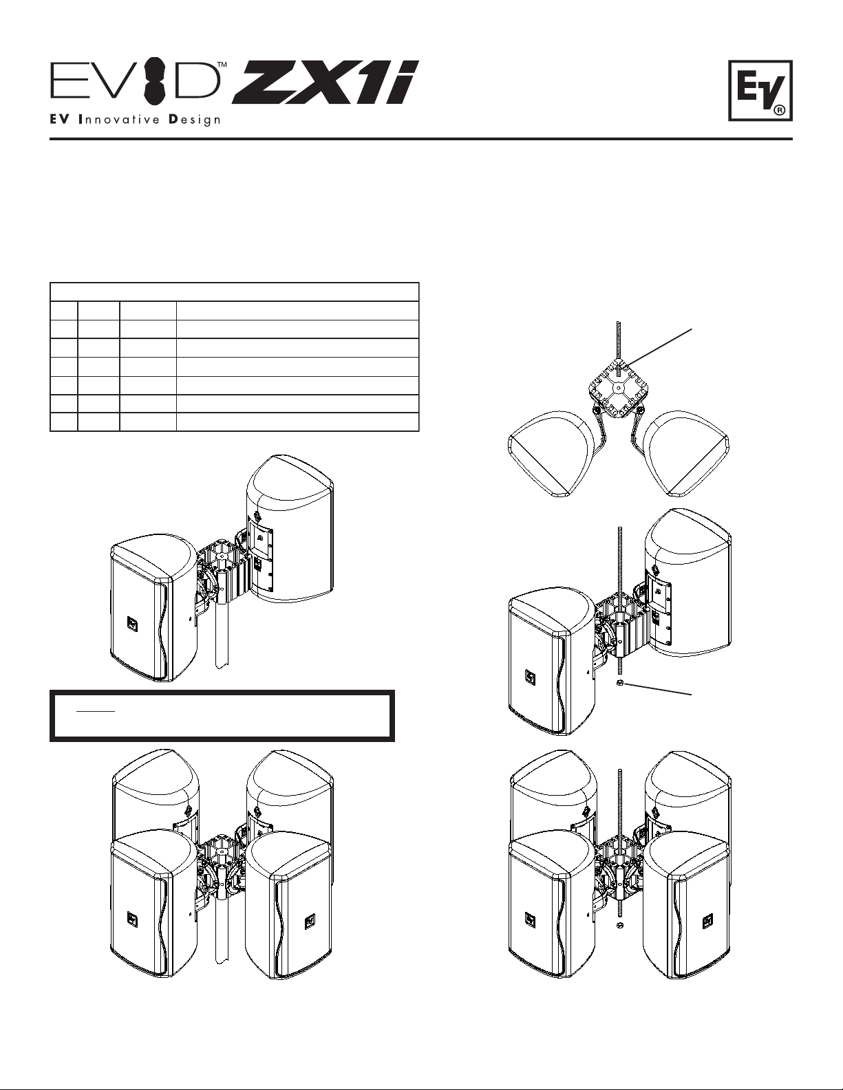
Sample Configurations:
3/8” Nut
(Not Included)
Note - Safety Bracket (Item 2) Not Needed for
Tripod Configurations
Figure 1:
Tripod Mounting Configurations
(2 and 4 Systems)
3/8” Nut
(Not Included)
Figure 2:
Threaded Rod Suspension Configurations
(2 and 4 Systems, Horizontal and 45°)
Page 2
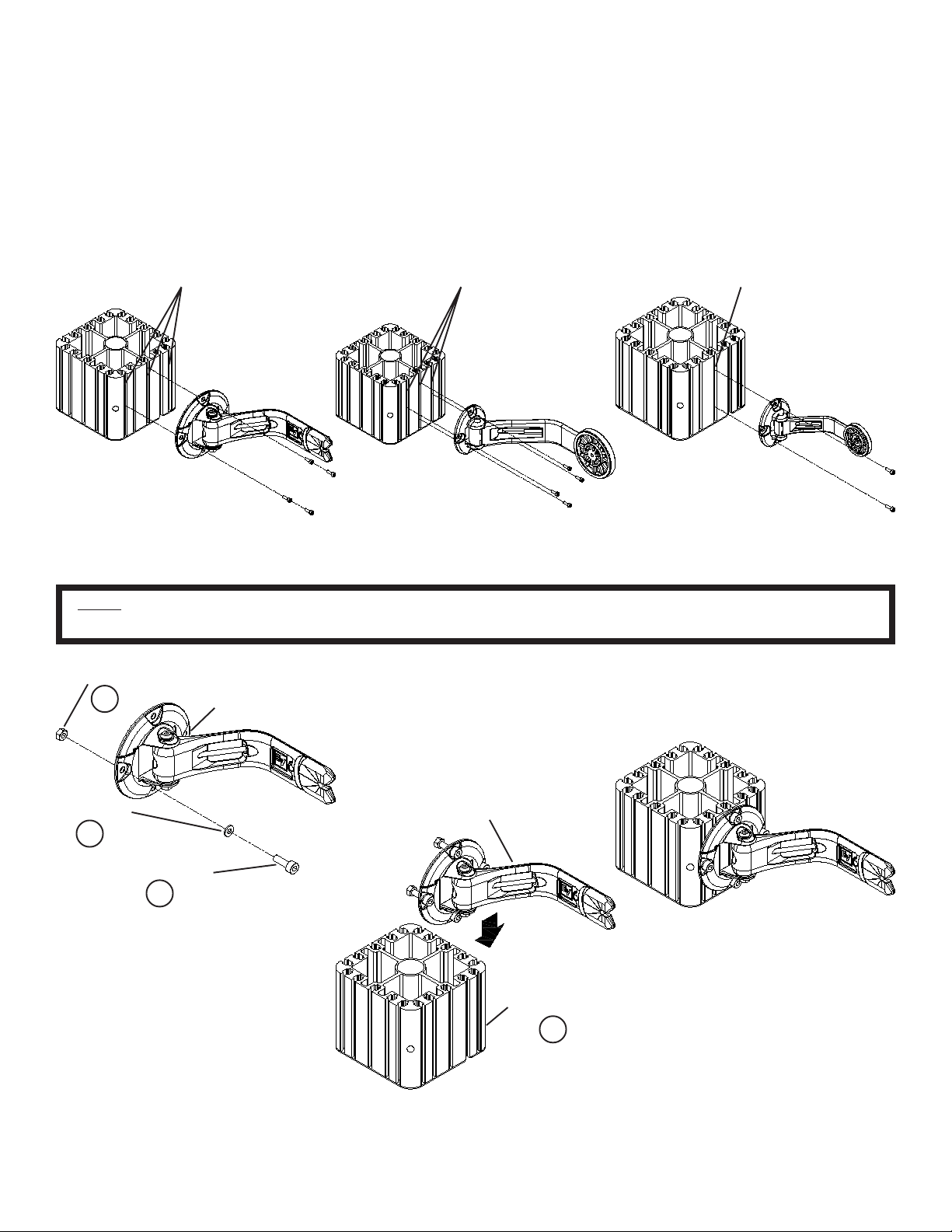
T o Attach the Strong Arm Mounts to the Array Bracket:
1. There are five channels on each side of the array bracket that correspond to different Strong Arm Mounts. ZX1i
loudspeakers use the center channel and the two outer channels (Figure 3a), EVID 4.2 and 6.2 loudspeakers use the
middle three channels (Figure 3b), and the EVID 3.2 uses the center channel only (Figure 3c).
2. Insert the (4) 1/4-20 x 3/4" bolts (Item 4) into the (4) washers (Item 5) and Strong Arm Mount (included with
loudspeaker). Fasten the (4) lock nuts (Item 3) on the bolt by hand; the nut should be loose (Figure 4a).
3. Slide the (4) nuts into the appropriate channels on the array bracket (Item 1) until approximately centered (Figure 4b).
Securely tighten the bolts using a 3/16" hex wrench (Figure 4c).
4. Repeat steps 1-3 for either two or four loudspeakers.
Center and T wo Outer
Channels Used
Figure 3a:
Array Bracket Channel
Configuration - ZX1i Series
Note - For Arraying EVID 3.2’s, only (2) Nuts, Bolts, and Washers are Needed for Mounting. Only Use the Top
and Bottom Holes in the Strong Arm Mount. All Other Models Use (4) Nuts, Bolt s, and Washers for Mounting.
1/4-20 Nut
3 (x4)
Strong Arm Mount
(Included with
Speaker)
Array Bracket Channel
Configuration - EVID 4.2 and 6.2
Middle Three
Channels Used
Figure 3b:
Only Center
Channel Used
Figure 3c:
Array Bracket Channel
Configuration - EVID 3.2
Washer
5 (x4)
1/4-20 Screw
4 (x4)
Figure 4a:
Loosly Assembling Fasteners to
Strong Arm Mount
Strong Arm Mount
with Fasteners
Loosly Assembled
Figure 4c:
Strong Arm Mount to Array
Bracket Completed Assembly
Array Bracket
1
Figure 4b:
Assembling Strong Arm Mount
to Array Bracket Channels
Page 3

To Attach the Array Bracket to a 3/8" Threaded Rod (Horizontal Configuration):
1. Fasten a 3/8" nut (not included) at least 2.75" from the bottom of the 3/8" threaded rod (Figure 5). Apply nonpermanent threadlocker, such as Loctite 242, to the nut.
2. Slide the array bracket assembly and safety bracket (Item 2) over the threaded rod, with the larger diameter hole
facing up and the safety bracket tabs locked in the channels of the array bracket (Figure 5).
3. Rotate the array to the desired position, and securely tighten a 3/8" nut on the threaded rod. Apply a non-permanent
threadlocker, such as Loctite 242, to the nut, and check to ensure that all threads on the nut are engaged to the
threaded rod (Figure 5).
4. It is strongly recommended that safety cables be attached from each loudspeaker to the top of the array bracket for
added safety. Loop around the threaded rod and around the safety suspension point of the loudspeaker (Figure 6a).
5. It is strongly recommended that an additional safety cable be attached from the array bracket to a point on the beam
for added safety. Loop through the corner hole of the array bracket to a point on the beam that the threaded rod is
attached to (Figure 6b).
Threaded Rod
3/8” Nut
(Not Included)
Array Bracket
1
Safety Cables
(Speaker to Rod)
Figure 6a:
Attaching Safety Cables from Each
Loudspeaker around Threaded Rod
Safety Bracket
2
3/8” Nut
(Not Included)
Figure 5:
Attaching Array Bracket Assembly
to Threaded Rod
Safety Cable
(Bracket to Beam)
Figure 6b:
Attaching Safety Cables from Array Bracket
to Overhead Structural Support Beam
Page 4

To Attach the Array Bracket to a 3/8" Threaded Rod (Diagonal Configuration):
1. Apply non-permanent threadlocker, such as Loctite 242, to the 3/8" threaded rod and thread the array bracket onto the
rod, using the corner hole. Leave approximately 1.5" of the threaded rod inside the array bracket (Figure 7a).
2. Apply non-permanent threadlocker, such as Loctite 242, to the 3/8" threaded rod and fasten the nut to the threaded
rod unit it touches the array bracket (Figure 7b). Check to ensure that all threads on the nut are engaged to the
threaded rod.
3. It is strongly recommended that safety cables be attached from each loudspeaker to the top of the array bracket for
added safety. Loop around the threaded rod and around the safety suspension point of the loudspeaker (Figure 8).
Array Bracket
Threading Array Bracket onto
Bottom of Threaded Rod
Figure 7a:
Threaded Rod
Safety Cables
(Speaker to Rod)
Array Bracket
3/8” Nut
(Not Included)
Threading Nut to Bottom of
Threaded Rod
Figure 7b:
Threaded Rod
Attaching Safety Cables from Each
Loudspeaker around Threaded Rod
WARNING: Suspending any object is potentially dangerous and should only be attempted by individuals who have a
thorough knowledge of the techniques and regulations of rigging objects overhead. Electro-Voice® strongly
recommends that all speakers be suspended taking into account all current national, federal, state and local regulations.
It is the responsibility of the installer to ensure that all speakers are safely installed in accordance with all such
regulations. If EVID or ZX1i speakers are suspended, Electro-Voice® strongly recommends that the system be inspected
at least once a year. If any sign of weakness or damage is detected, remedial action should be taken immediately.
12000 Portland Avenue South, Burnsville, MN 55337
Phone: 952/884-4051, Fax: 952/884-0043
www.electrovoice.com
© Telex Communications, Inc. 8/2006
Part Number 38110-517 Rev A
Figure 8:
U.S.A. and Canada only. For customer orders,
contact the Customer Service department at
Europe, Africa and Middle East only. For customer orders,
For warranty information, contact the Service Repair department at:
For technical assistance, contact Technical Support at:
Specifications subject to change without notice.
800/392-3497 Fax: 800/955-6831
contact the Customer Service department at
49 9421-706 0 Fax: 49 9421-706 265
616/695-6831 or 800/685-2606
866/78AUDIO
 Loading...