

Page 1
AB-32 / AB-62 Array Bracket System
Assembly and Installation Instructions
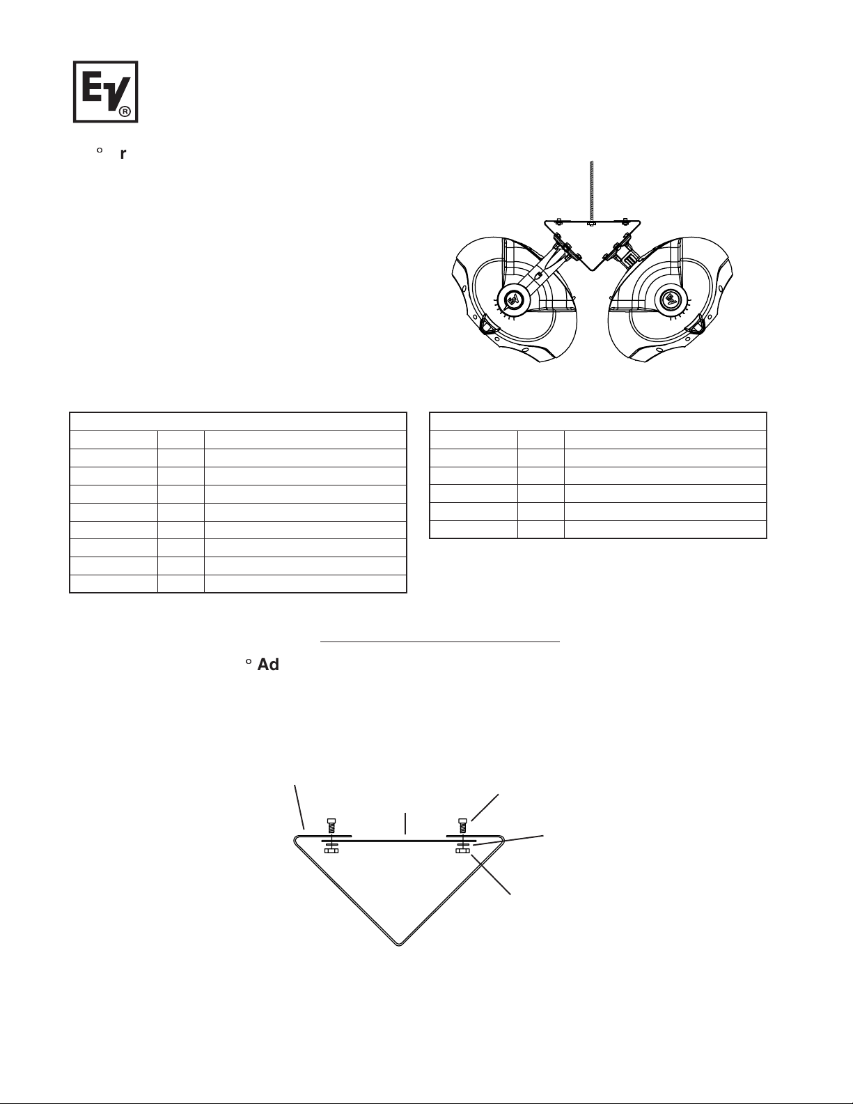
180° Array Bracket Kit
AB-32 and AB-62 series kits feature a 2 sided powder
coated steel mounting assembly that allows the mounting of 2 EVID speakers into a 180° pattern array configuration. The AB-32 works with the EVID 3.2 series
and can be used with a threaded rod for suspension
from the ceiling. The AB-62 allows the EVID 4.2 or 6.2
series speakers to be used with a speaker stand tripod
or hung from the ceiling utilizing a threaded rod as shown.
The EVID’s position can then be adjusted using the
Strong Arm Mount™ to cover a variety of patterns to
best serve the installation requirements.
All assembly hardware is included in packaging.
sedulcnItiKtekcarByarrA°0812.3divE
metI.ytQnoitpircseD
11 2.4/2.6divE,tekcarByarrA
21 2.4/2.6divE,retpadAyarrAlacitreV
321"5.x02-4/1,wercS
461).aiDedisnI"4/1(,rehsaWtalF
56102-"4/1,tuNkcoL
64 "5.x02-4/1,wercSdaeHtalF
710812.4/2.6divE,retpadAyarrA°
81 tnuoMeloP
sedulcnItiKtekcarByarrA°0812.4/2.6divE
metI.ytQnoitpircseD
11 2.3divE,tekcarByarrA
21 2.3divE,retpadAyarrAlacitreV
321"5.x02-4/1,wercS
421).aiDedisnI"4/1(,rehsaWtalF
52102-"4/1,tuNkcoL
Ceiling Suspension (All Sizes)
Step 1: Assemble 180°ÿAdapter Plate
Assemble the Vertical Array Adapter (Item 2, Fig. 1) to the Array Bracket (Item 1) using 4 Screws (Item 3), 4 Flat
Washers (Item 4), and 4 Lock Nuts (Item 5) as shown in Figure 1.
(Item 1)
Array Bracket
(Item 2)
Vertical
ArrayAdapter
(Item 3)
Screws
(Item 4)
Flat
Washers
Lock Nuts
Figure 1
Evid 6.2/4.2/3.2 Bracket Assembly for
Threaded Rod Installation
(Item 5)
Page 2
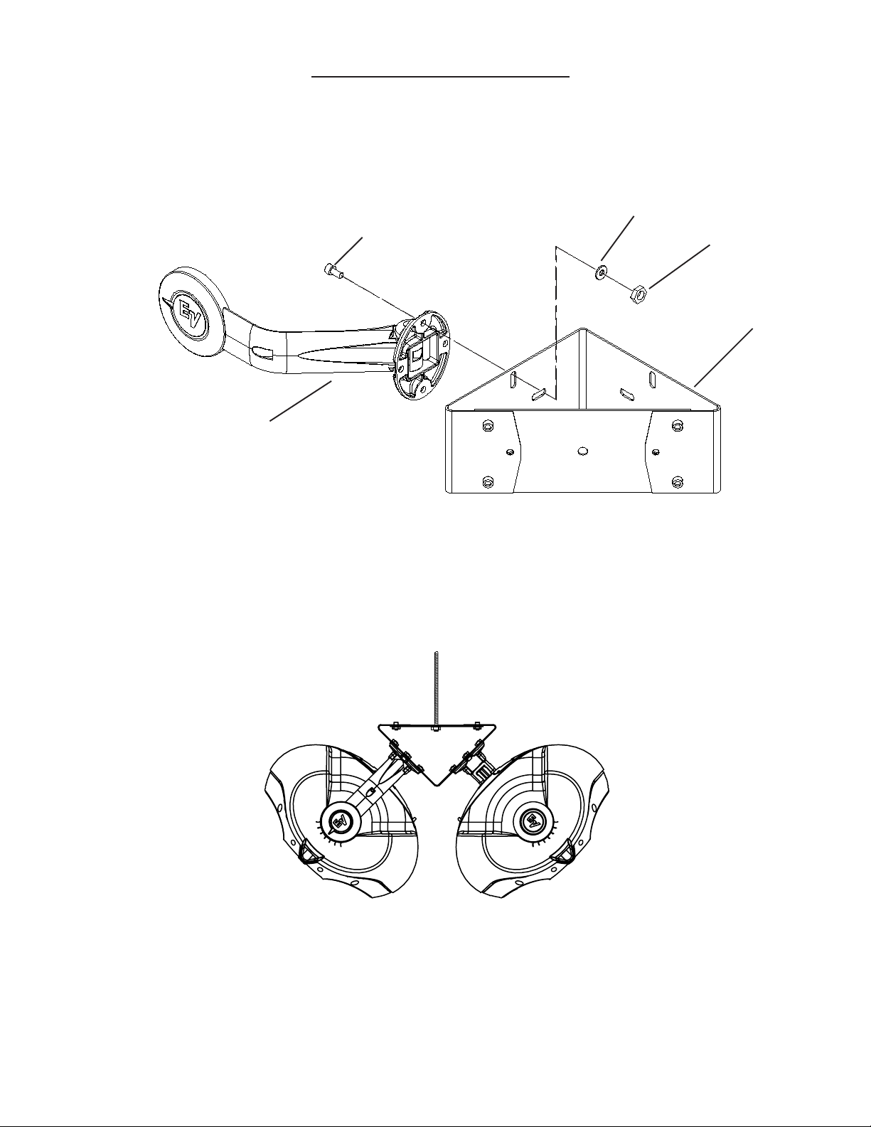
Ceiling Suspension (Continued)
Step 2: Assemble SAM’s to Array Bracket
Attatch the Strong Arm Mounts to the Array Bracket (Item 1) using 4 Screws (Item 3), 4 Flat Washers (Item 4), and 4
Lock Nuts (Item 5) per SAM as shown in Figure 2.
(Item 4)
Flat
(Item 3)
Screws
Strong-Arm
Mount
(SAM)
Washers
(Item 5)
Lock Nuts
(Item 1)
Array Bracket
Figure 2
Evid 6.2/4.2 Bracket Assembly
Figure 3
Threaded Rod Installation
Page 3

Tripod Mounting (6.2/4.2 only)
Step 1: Assemble Array Bracket and
180° Array Adapter
Assemble 180° Array Adapter (Item 7) to the
Array Bracket (Item 1) using 4 Screws (Item 3), 4
Flat Washers (Item 4) and 4 Lock Nuts (Item 5) as
shown in Figure 4.
(Item 1)
Array Bracket
Figure 4
Step 2: Assemble SAM’s and Array Bracket
Assemble Strong Arm Mounts to the Array Bracket (Item 1) using
4 Screws (Item 3), 4 Flat Washers (Item 4) and 4 Lock Nuts (Item
5) on each Strong Arm Mount as shown in Figure 5. Three of the
four bolts on each Strong Arm Mount will be used to attach the
180° Array Adapter (3).
(Item 3)
Screws
(Item 3)
Screws
(Item 7)
180° Array Adapter
NOTE: Three of the four bolts on each
Strong Arm Mount should be used to attach
the Array Adapter to the Array Bracket.
(Item 4)
Flat
Washers
(Item 4)
Flat
Washers
(Item 5)
Lock Nuts
Strong-Arm Mount
(SAM)
Step 3: Assemble Pole Mount
and 180° Array Adapter
Assemble Pole Mount (Item 8) to the
180° Array Adapter (Item 7) using 4Flat
Head Screws (Item 6), 4 Flat Washers
(Item 4) and 4 Lock Nuts (Item 5) as
shown in Figure 6.
Figure 5
(Item 7)
180° Array Adapter
(Item 5)
Lock Nuts
(Item 1)
Array Bracket
(Item 5)
Lock Nuts
(Item 4)
Flat
Washers
(Item 8)
Pole Mount
Figure 6
(Item 6)
Flat Screws
Page 4

This guide provides instruction on how to use EVID components to create example arrays. Correct use of this
hardware is required for secure array construction. Only persons with the knowledge of proper hardware and safe
suspension techniques should attempt to suspend any sound systems overhead. CAUTION! The weakest
component determines the size and safety of the entire array. Before suspending any array always inspect all
components of the array including building structural supports for cracks, deformations, corrosion or damage that
could reduce strength and safety of the array.
It is the responsibility of the user to ensure that any Electro-Voice loudspeaker system is suspended overhead in
accordance with all current federal, state, and local regulations.
© Telex Communications, Inc. 11/2001
Part Number 38110-063 Rev A
Suspension Safety Warning
12000 Portland Avenue South, Burnsville, MN 55337
Phone:952/884-4051, Fax:952/884-0043
www.electrovoice.com
 Loading...