

Page 1
1700 Series
Mixer/Power Amplifiers
Operating Instructions
Page 2

TABLE OF CONTENTS
DESCRIPTION................................................................................................................................................................................... 3
INCLUDED ACCESSORIES: ............................................................................................................................................................. 3
OPTIONAL INPUT OUTPUT ACCESSORY MODULES: .................................................................................................................. 3
ELECTRICAL CONNECTIONS FOR THE 1700 SERIES MIXER/POWER AMPLIFIERS ................................................................ 3
Power Connections (120 Volt, 50/60 Hz) .................................................................................................................................... 3
Power Connections (100, 200, 220, or 240 Volt; 50/60 Hz) 1707C/1715C Only ........................................................................ 3
INSTALLING MODULES IN THE MAINFRAME................................................................................................................................. 4
SHELF OR RACK MOUNTING THE ................................................................................................................................................. 4
Ventiliation .................................................................................................................................................................................. 4
OUTPUT CONNECTIONS (1707C/1715C Only) .............................................................................................................................. 6
MUTE/TONE GENERATOR CONNECTIONS ................................................................................................................................... 6
PREAMP OUT/AMP IN CONNECTIONS .......................................................................................................................................... 7
AUX OUT CONNECTIONS................................................................................................................................................................ 7
BATTERY INPUT CONNECTIONS .................................................................................................................................................... 7
FRONT/REAR-PANEL CONTROLS, SWITCHES, INDICATORS, AND CONNECTORS ........................................................... 8
INITIAL SETUP AND OPERATION OF .............................................................................................................................................. 8
MAINFRAME WITH MODULES INSTALLED .................................................................................................................................... 8
Initial Setup of an Input Module .................................................................................................................................................. 8
Initial Setup of an Output Module ............................................................................................................................................... 8
Initial Setup of the Mainframe ..................................................................................................................................................... 8
OPERATING THE 1700 SERIES MIXER/POWER AMPLIFIERS ...................................................................................................... 8
1781 Mic/ Line Input Module......................................................................................................10
DESCRIPTION................................................................................................................................................................................. 10
INSTALLATION OF OPTIONAL 1785A INPUT ISOLATION TRANSFORMER................................................................................ 10
CONFIGURING THE 1781A ............................................................................................................................................................ 10
PROGRAMMING THE 1781A .......................................................................................................................................................... 10
Mute”Priority” Mode of Operation ............................................................................................................................................. 10
Mute “Slave” Mode of Operation ............................................................................................................................................... 10
Mute “Off “ Mode of Operation .................................................................................................................................................. 11
Phantom Power ........................................................................................................................................................................ 11
REMOTE VOLUME CONTROL CONFIGURATIONS ...................................................................................................................... 11
Remote Volume Control Connections ....................................................................................................................................... 11
Alternative Configurations Using the RVC Circuitry for Preset Attenuation ............................................................................. 12
Simultaneous Remote Volume Control of Several Input Modules ............................................................................................ 12
CONNECTOR OPTIONS FOR THE 1781A ..................................................................................................................................... 12
USE OF HIGH LINE LEVEL INPUT SIGNAL SWITCH THE 1781A................................................................................................ 12
ALTERNATIVES TO THE EXTERNAL RESISTIVE PAD ................................................................................................................. 12
SPECIFICATIONS ............................................................................................................................................................................ 13
1783 Line Output Module...........................................................................................................14
CONFIGURING THE 1783 .............................................................................................................................................................. 14
CONNECTOR OPTIONS FOR THE 1783 LINE OUTPUT MODULE .............................................................................................. 14
INCLUDED ACCESSORIES: ........................................................................................................................................................... 14
INSTALLATION OF OPTIONAL 1786 OUTPUT ISOLATION TRANSFORMER .............................................................................. 15
VOX GATE ...................................................................................................................................16
DESCRIPTION................................................................................................................................................................................. 16
MODIFICATION A (REFERENCE FIGURE 1): ................................................................................................................................ 16
MODIFICATION B (REFERENCE FIGURE 1): ................................................................................................................................ 16
2
Page 3
DESCRIPTION
The 1700 Series Mixer/Power Amplifiers offer a highly flexible
integration of a user configurable six input mixer with a fully
protected power amplifier in one convenient cost effective
package.
The six input ports accept any of the several input modules or
output module. The programmable input modules may have their
muting circuitry configured in either “priority”, “slave” mode, or
may be set to ignore muting commands. When a module
configured in the “Priority” mode is activated, modules in the
“slave” mode will be muted.
Circuitry is also provided to allow remote volume control of
individual inputs.
Multiple mainframes may be dynamically linked together.
Separate preamp-out and amplifier-in jacks allow the insertion
of equalizers or other, signal processing between the mixer and
the power amplifier.
A multi-tone generator and a compressor/limiter are also
provided.
INCLUDED ACCESSORIES:
1 - Operating/Service Instruction documents.
1 - Shorting Bar (Installed on Direct Output to OT in).
1 - “U” Shorting Bar (Installed on Preamp Out to Amp In).
4 - Rubber Feet (installed).
1 - System Configuration Label installed on top cover.
1 - International fuse.
1 - International 220/240 VAC voltage sticker.
1 - International Fuse sticker.
1 - Rack mount hardware kit.
OPTIONAL INPUT OUTPUT ACCESSORY
MODULES:
1781A Programmable Input Module.
1781AT Programmable Input Module with 1785A 600 ohm
to 10 kohm isolation transformer installed.
1783 Line Output Module.
1785A 600 ohm to 10 kohm Input Isolation Transformer.
1786 600 ohm to 600 ohm Output Isolation Transformer.
1791 Female XLR Connector.
1792 Male XLR Connector.
1793 Dual RCA Phono Connector.
1794 5-Lug Screw Terminals.
ELECTRICAL CONNECTIONS FOR THE 1700
SERIES MIXER/POWER AMPLIFIERS
Power Connections (120 Volt, 50/60 Hz)
The mainframe configuration for both mixer/ power amplifiers
comes with the power transformer’s primary line voltage
strapped for 120-volt operation from the factory. Refer to Table
1 for exact strapping details and other voltage options.
NOTE:
Make sure the line voltage corresponds with the
selected line voltage power rating BEFORE you
connect the mainframe to the alternating current
line.
Power Connections (100, 200, 220, or 240 Volt; 50/60 Hz)
1700C/1715C Only
trahCgnippartSdnanoitceleSegatloVeniLCA.1elbaT
yramirP
eniL
egatloVetihWwolleYdeReulBegnarO
v001521193
V021251139
V002527018
V022527801
V042257801
roloCdaeLyramirPremrofsnarT
You may change the mixer/power amplifier’s 120-volt power
connection to a 100-, 200-, 220-, or 240-volt power connection
by restrapping the power transformer’s primary line voltage. Use
the following procedure to change the factory strapping to
another line voltage.
1. If you connected the mixer/power amplifier to an
alternating current power source, disconnect it.
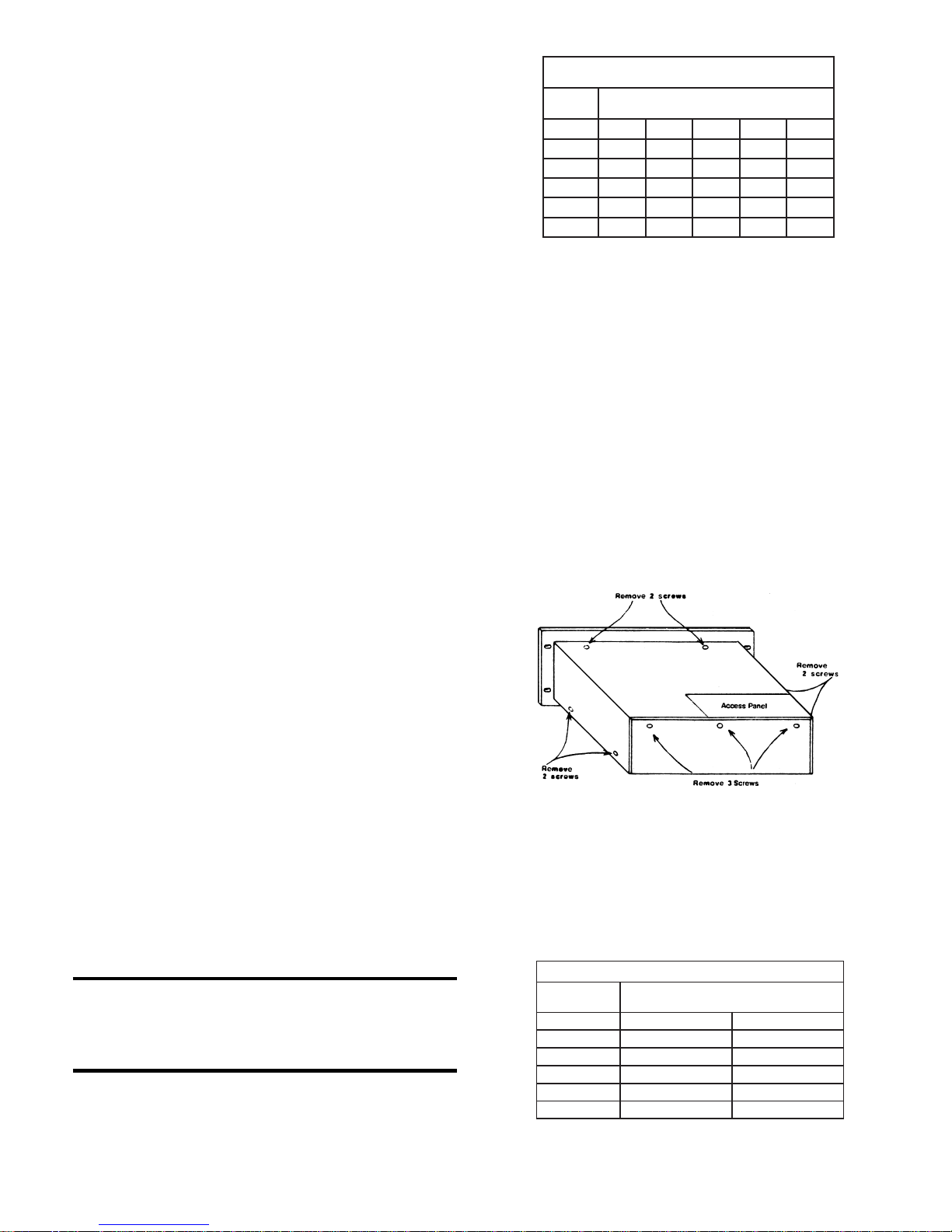
2. Remove and save the nine screws that secure the mixer/
power amplifier’s top cover. There are two screws near
the bottom of each side, two screws on top near the rear
edge of the front panel, and three screws at the top edge
of the rear panel. Refer to Figure 1 for details.
The numbers in Table 1 correspond to the numbered
positions on the alternating current terminal block
connector, which is adjacent to the power transformer. To
select a line voltage, install the colored primary lead wires
into the corresponding numbered positions on the terminal
block.
3. Locate the voltage selection terminal block between the
side of the chassis and the power transformer.
Figure 1. Top Cover Removal
4. While referring to Table 1, disconnect the primary lead
wires from the terminal block. Pull each wire firmly to
disengage the push-on connector. Then reconnect each
lead wire into its designated position on the terminal block
that corresponds to the desired line voltage. Press each
connector to snap into place.
trahCnoitceleSesuFCA.2elbaT
eniLCA
egatloV
C7071
V001V052/A5.3V052/A0.7
V021V052/A5.3V052/A0.7
V002V052/A0.2V052/A0.4
V022V052/A0.2V052/A0.4
V042V052/A0.2V052/A0.4
esuFeniLCA
C5171
3
Page 4
5. Install the appropriate fuse value from Table 2.
NOTE:
Use of fuses other than those listed in Table 2 will
VOID THE W ARRANTY .
6. If you connected the power transformer’s primary leads
for 200-, 220-, or 240-volt operation, perform steps 7, 8,
and 9 below to prevent future confusion and possible
damage to the amplifier. Otherwise, proceed with step
10 below.
7. Affix the supplied 220/240 VAC label above the power
cord and cover the 120 VAC silkscreened designation.
8. Affix the 2-amp fuse/1707C, (4-amp/
original 3.5 amp/1707C, (7-amp/1715C) silkscreened
designation.
1715C) label over the
9. Replace the standard AC line fuse with the 2-amp fuse/
1707C, (4-amp/1715C) supplied. You should find the
labels and the fuse enclosed in the plastic bag with this
manual. Refer to Table 2 for an AC fuse selection chart.
10.If you are not installing additional modules in the
mainframe right now, reinstall and secure the top cover
with the nine screws previously removed in step 2 above.
NOTE:
Y ou can buy and install additional modules into the
mixer/power amplifier , which has six ports that you
can configure as input or output modules.
INSTALLING MODULES IN THE MAINFRAME
1. Remove and save the two screws that secure the access
panel to the top cover. Refer to figure 1 for details.
2. Plug the input or output module into one of the six channel
positions with the controls facing the rear as shown in Figure
Figure 2. Module Installation
2. Secure the module with the two screws provided.
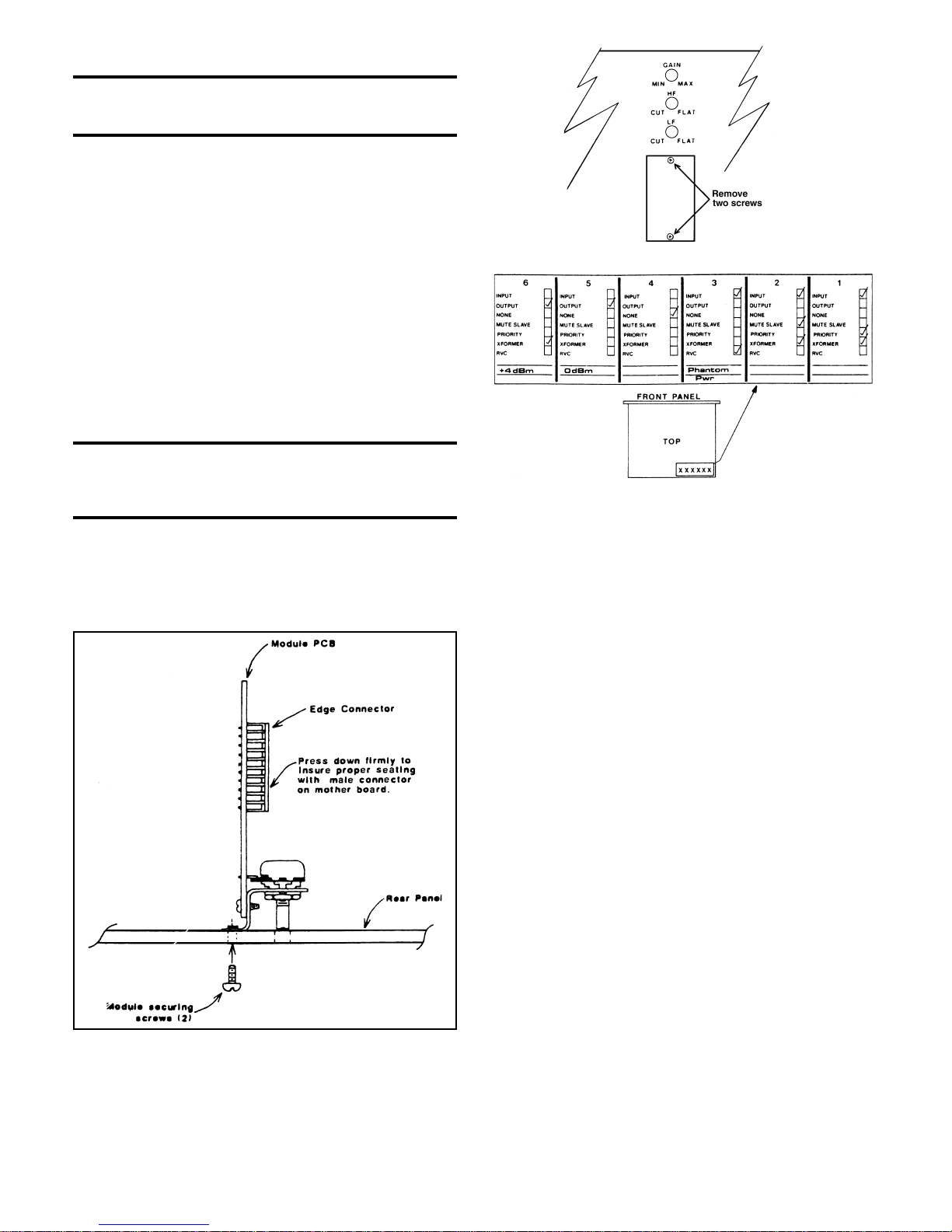
3. Remove the blank cover panel as shown in Figure 3. Install
the selected connector assembly with the screws provided.
Figure 3. Removal of Blank Cover Panel
Figure 4. System Configuration Label
Plug the pigtail connector (from the main connector
assembly) onto its appropriate male mating connector on
the module’s printed circuit board.
4. On the top cover is a System Configuration Label. Use it to
indicate the module type, configuration, and any options for
future reference. Write directly on the label with a permanent
marker. Refer to Figure 4 for a sample of this label.
SHELF OR RACK MOUNTING
You may shelf mount or rack mount the mainframe. For shelf or
countertop applications, four rubber feet on the bottom of the
chassis will protect resting surfaces and provide elevation for
air flow underneath the unit. For rack or cabinet applications,
remove the four rubber feet from the bottom of the chassis. Then
install the unit in the rack with the screws and shoulder washers
provided. The unit must have 1.75" of blank space both above
and below it.
Ventiliation
The mixer/power amplifier generates minimal heat during normal
use. Although the amount of generated heat is low, make sure
the mainframe is property ventilated to prevent an excessive
temperature rise. Because the output power devices (transistors)
are sensitive to heat, you should not place the amplifier between
other heat generating equipment or in areas where the ambient
temperature exceeds 50°C (122°F).
If you mount the mainframe in an equipment rack or cabinet
with other heat producing equipment, provide adequate space
between the units. Otherwise, the equipment may become too
warm.
If a rack or cabinet contains several amplifiers, you may need
to check the ambient air temperature. To determine the ambient
air temperature, operate the system until the temperature
stabilizes. Measure the ambient air with a bulb-type thermometer
held at the bottom of the uppermost amplifier.
4
Page 5
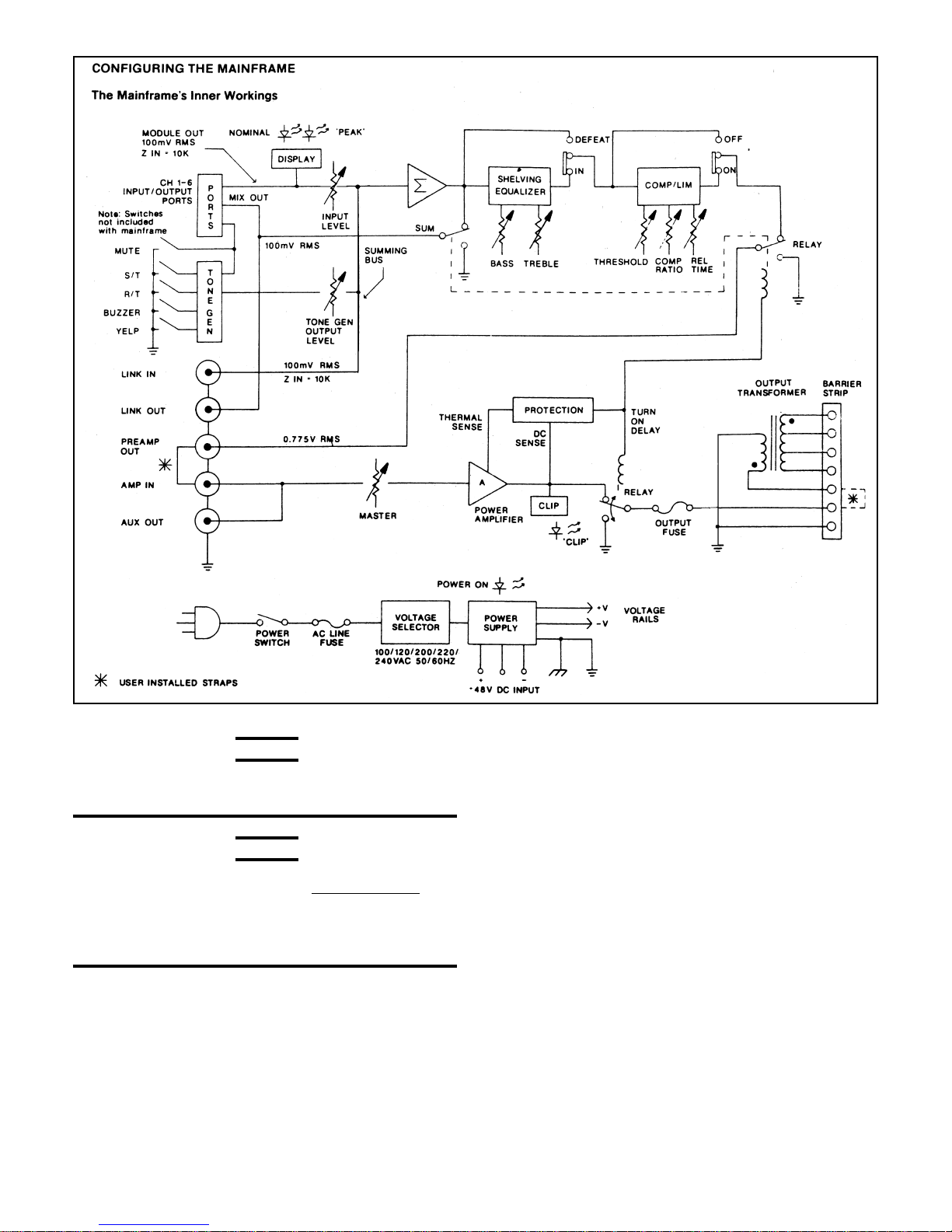
Figure 5. Block Diagram of 1707C / 1715C Mixer/Power Amplifiers
CAUTION
Don’t let the thermometer bulb touch the metal
chassis. The chassis might be hotter than the
ambient air.
CAUTION
If the air temperature exceeds 60°C (140°F), place
the equipment farther apart or install a blower to
provide air movement within the cabinet. Make sure
you don’t block the air intake holes located on the
bottom of the chassis or the exhaust holes on the
top cover.
Figure 5 above displays a block diagram of the mixer/power
amplifier mainframe. Study it carefully. To use the system’s full
capabilities, you’ll need a good understanding of the inner
workings of the mainframe. Brief explanations of how the inside
of the mainframe works follow in the text below.
The signal coming from each additional input module
simultaneously routed to the mixer/power amplifier’s front-panel
nominal/peak LED indicators and to the input channel level
controls. The dual LED nominal/peak displays are pre-fader and
designed to monitor the output level from the corresponding
input module. The nominal (green) LED indicators have an
approximate 10 dB window over which they will illuminate. This
makes it easy to properly adjust the gain for each input module
while efficiently using the rest of the system in terms of
performance and headroom.
The mixer/power amplifier then sums the signal at the wiper of
each input channel level control into a true virtual ground
summing node or bus. The summing amplifier has eight input
channels - input channels one through six on the front panel,
tone generator output, and the link input or LINK IN on the rear
panel. The summing amplifier’s output signal drives the link
output, or LINK OUT, located on the rear panel of the mainframe.
The E.Q. and compressor/limiter sections are in series with each
other, as shown in Figure 5. The compressor/limiter’s output
signal drives the preamplifier output, or PREAMP OUT, located
on the rear panel which then provides the input signal to the
main amplifier section.
The BASS and TREBLE E.Q. controls are ideally suited to make
adjustments to the overall response of the mix. The low and
high frequency shelving equalizers provide ±12 dB of boost
5
Page 6
and cut with the maximum boost occurring at 100 Hz and 10kHz
respectively.
The compressor/limiter section features variable release time,
compression ratio, and threshold. The circuit uses a feed-forward
topology that will minimize level differences for a more nearly
constant output level. The compression ratio can approach ¥ :1,
and the attack time is fixed at approximately 10 ms.
The main amplifier section protects itself and the load against
radio frequency interference, spurious oscillatory waveforms,
excessive temperatures, direct current, turn-on/turn-off
transients, and excess voltage/current phase shift due to reactive
loading.
A signal overload circuit monitors the level at the output stage
of the amplifier section. The front-panel CLIP LED indicator
illuminates when signal levels are high enough to cause
significant output clipping.
A dual slope V-I limiter protects the output devices. It keeps the
output devices operating within their SOA (safe operating area)
as defined by the device manufacturer.
A special integrated circuit function block monitors the heatsink
temperature, powersupply voltage, and the amplifier’s output.
When it detects a problem, it immediately disengages the output
relay.
Output Connections (1707C/1715C Only)
Make output connections to the seven-terminal barrier strip
connector located on the lower-left side of the mainframe’s rear
panel.
The 1707C main output connections include an 8 ohm direct
output (24.5 vrms) and three transformer balanced outputs; 4
ohm (17.4 vrms), 25 vrms (8.3 ohm), and 70.7 vrms (66.6 ohm).
The 1715C main output connections include a 4 ohm direct
output (24.5 vrms) and a 25 vrms (4.2 ohm), an 8 ohm (34.6
vrms), and a 70.7 vrms (33.3 ohm) balanced transformer output.
Refer to Figure 6 for a display of the direct output connections
and Figure 7 to see the transformer output connections.
Figure 6. Direct Output Connections
Output Fuse: A fuse in series with the output of the amplifier
section protects the amplifier from excessive current
consumption by a load. If this output fuse blows, replace it only
with a fuse that matches the same type and rating as
silkscreened on the rear panel of the unit. If the fuse continues
to blow. check the load to see if it shorted or is exceeding the
rated power consumption. If the problem continues, have a
qualified service technician service the unit.
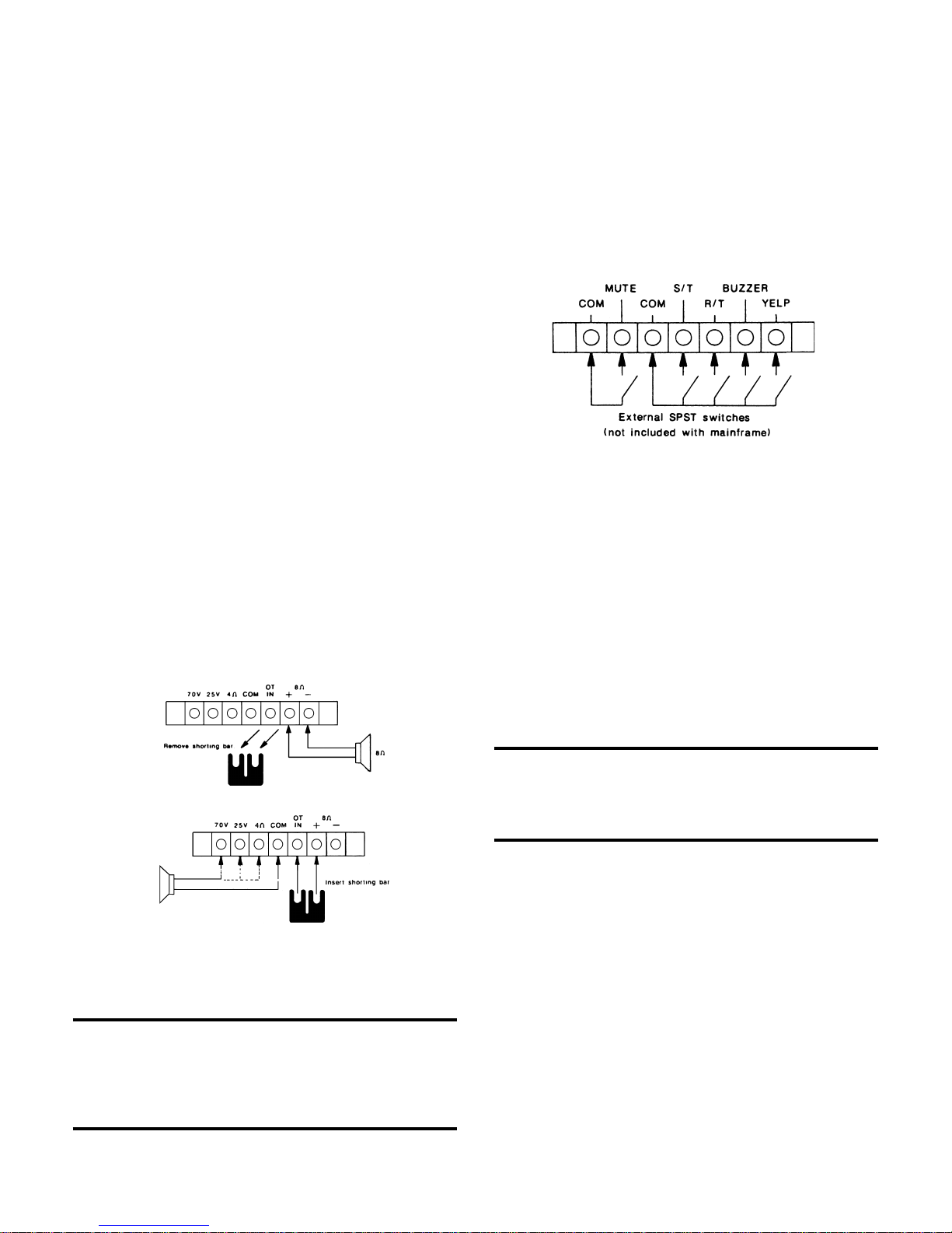
Mute/Tone Generator Connections
The seven-lug screw terminal connector located on the mid-left
rear of the mainframe provides access to the system mute and
tone generator. For connection details, refer to Figure 8.
Figure 8. Mute/Tone Generator Switch Connections
A switch closure between the mute and common (COM)
terminals will mute any input modules configured in the slave
mode. You can use the remaining switches to select one of the
following sounds:
A single-tone chime (S/T),
A repeating-tone chime (R/T),
A buzzer, or
A yelp (siren).
For the duration of a tone, the tone generator automatically
mutes any input modules configured in the slave mode.
Output-Level Control:
The tone generator’s output-level control is conveniently located
on the rear panel of the mainframe. To increase the tone
generator’s output level, rotate the screwdriver-slotted control
shaft clockwise.
NOTE:
Optional External Mute, (connected at the factory)
allows external muting of the tone generator. If
disconnected, the tone generator cannot be
externally muted.
Figure 7. Transformer Output Connections
To use a transformer balanced output, install a U shorting bar
between the direct (+) output and the output transformer’s input
(OT IN).
NOTE:
When using the output transformer, you may use
any combination of output connections as long as
the total connected load does not consume more
than 75 watts for the 1707C or 150 watts for the
1715C.
Resistance Effects of Long-Cable Runs on Mute/Tone
Generator Circuits:
Table 3 shows the maximum allowable cable resistance (total
resistance) that the mixer/power amplifier can support.
Resistances greater than these values, resulting from
excessively long-cable runs or small gauge wire, may cause
the mute or tone generator circuitry to fail to operate. Please
make sure all cable resistances are less than the values shown
in Table 3.
6
Page 7

Table 3. Maximum Allowable Cable Resistances
noitcnuF)smho(ecnatsiseR
emihCT/Sk31
emihCT/Rk8.51
rezzuBk8
pleYk8
etuMk8
LINK IN/LINK OUT Connections
The LINK IN/LINK OUT phono connectors on the mid-rear panel
of the mainframe permit you to dynamically
link
two or more
systems together. If you require more channels, the 1707C/
1715C mixer/power amplifiers are fully compatible with 1700C
mixer/preamplifier.
The signal appearing at the LINK OUT connector is the
summation of all input channels as mixed by the input channel
level controls. LINK IN is a direct input to a system’s mixing
amplifier; it’s also a seventh input channel.
To link two units together, connect LINK OUT of system one to
LINK IN of system two. System two will now control the mix of
up to twelve input channels. Please refer to Figure 9 for typical
linking connections.
NOTE:
The LINK OUT signal is not affected by the
compressor/limiter or the E.Q. circuits.
PREAMP OUT/AMP IN CONNECTIONS
The PREAMP OUT signal is a mix of all input channels
processed by the compressor/limiter and tone control circuits.
Normally, you would insert a U shorting bar between the
PREAMP OUT and AMP IN phono connectors on the rear panel.
However, you can remove the shorting bar to patch in an external
equalizer or other signal processing device with a proper level
match of 0.775 vrms nominal. Figure 10 shows a typical
application using an external equalizer or other signal processing
device.
Figure 10. Patching an External Equalizer or Other Signal
Processing Device
AUX OUT CONNECTIONS
The auxiliary output (AUX OUT) phono connector on the rear
panel is wired directly (internally) to the AMP IN phono connector.
You can use it to drive a second amplifier or a tape recorder.
Please refer to the 1707C/ 1715C mixer/power amplifier’s block
diagram shown in Figure 5.
BA TTERY INPUT CONNECTIONS
You can power a system from the battery input connector for
auxiliary operation or standby switchover. The battery input
connector is the three-terminal barrier strip located on the
upper-left rear panel of the mainframe. The system requires
two ±48V DC battery power sources.
To connect the battery backup system to the three-terminal
barrier strip, follow the three steps shown in Figure 11.
Figure 9. Typical Linking Connections
Figure 11. Battery Input Connections
7
Page 8

FRONT/REAR-PANEL CONTROLS, SWITCHES,
INDICA TORS, AND CONNECTORS
Figure 12 below displays the front panel on the mixer/power
amplifier with numbers that point at each control, indicator, and
switch. You can find the corresponding number and name
description for each control, switch, or indicator in the text below.
Figure 12. Front-Panel Control, Switches,
and Indicators for the 1707C
5
13
4 3 6 9 7 10 11 8 12 1 2
INITIAL SETUP AND OPERA TION OF
metIemaNnoitpircseD/noitcnuF
1hctiwSREWOPhsup-hsupnoitisop-owT.rewopyramirpseilppA
2rotacidnIDELNOnehwhctiwsREWOPnoyalpsiddersetanimullI
3slortnoC6-1HC
4DELlauDdeR/neerG
srotacidnI
5DLOHSERHT
lortnoC
6EMITESAELER
lortnoC
7NOISSERPMOC
OITAR
lortnoC
8hctiwSFFO/NOehtfotuoronitiucricretimil/rosserpmocsecalP
9lortnoCSSAB
01lortnoCELBERTsedivorP.retemoitnetopelbairavylsuounitnoC
11TAEFED/NIQE
hctiwS
21leveLRETSAM
lortnoC
31rotacidnIDELPILCdaolrevolangislanretninanehwsetanimullI
:STUPNI sretemoitnetopelbairavylsuounitnoC
.htaplangis
:TUPTUO .retemoitnetopelbairavylsuounitnoC
.slortnoc
morf ∞ esaercniylsuoenatlumisottiesU.Bd0ot
.level
.edomffo/norofhctiws
.rewopnonrutuoy
morfdetaudarg ∞∞∞∞∞ roesaercninacuoY.Bd0ot
gnidnopserrochcaeroflevelesaerced
levelesaercniotesiwkcolcetatoR.lennahctupni
.levelesaercedotesiwkcolcretnuocdna
:LEVELTUPNI
)der(kaepdna)neerg(lanimonsyalpsiD
.lennahchcaerofnoitacidni
:RETIMIL/ROSSERPMOC elbairavylsuounitnoC
hcihwtalevelehtsenimreteD.retemoitnetop
.snigebgnitimil
lamronotnruterotmetsysehtrofderiuqereht
.dlohserhtwolebsllaflangisretfa
ehtybtessi,dlohserhtehtsdeecxeleveleht
.lortnocDLOHSERHT
nacuoY.esnopserssabnitucrotsoobsedivorP
.gnittesorezataesnopsertalfrolamronniatbo
roesnopsertsoobotesiwkcolcetatoR
.esnopsertucotesiwkcolcretnuoc
niatbonacuoY.esnopserelbertnitucrotsoob
.esnopsertucot
noitisopTAEFED.hctiwsnoitisop-owT
nehwslortnocELBERTdnaSSABstcennocsid
-atsuocAsahcus.noitacilpparofetairporppa
detaudargretemoitnetopelbairavylsuounitnoC
esiwkcolcetatoR.slennahctupnillaesaercedro
yamtahtslevellangistuptuohgihstcetedtiucric
.gnippilctuptuoesuac
MAINFRAME WITH MODULES INSTALLED
Initial Setup of an Input Module
You can buy and install the following input modules from
ElectroVoice:
The 1781A programmable input module. The 1781AT
programmable input module with 1785A input isolation
transformer, and the 1780A and 1780AT mic/line input modules.
To initially set up an input module, follow these steps:
1. Rotate the input module’s gain control to the 12:00 o’clock
(MID) position for planned microphone inputs or to the
MIN (fully counterclockwise) position for line-level inputs.
If the input type is unknown, rotate the gain control to the
MIN position.
2. Rotate the high-cut (HF) filter to the FLAT
position.
3. Rotate the low-cut (LF) filter to the FLAT
position.
Initial Setup of an Output Module
You can buy the 1783 line output module from ElectroVoice.
This module can be installed with or without the optional 1786
output isolation transformer (also available from Altec Lansing).
To initially set up an output module, rotate the output module’s
output level control (labeled GAIN on the rear panel) to the MIN
position.
Initial Setup of the Mainframe
1. Rotate the MASTER output level control on the front panel
of the mainframe to the position (fully counterclockwise).
2. Set the compressor/limiter ON/OFF switch to the OFF
position.
3. Set the tone control EO IN/DEFEAT switch to the DEFEAT
position.
Operating the 1700 Series Mixer/Power Amplifiers
senimreteD.retemoitnetopelbairavylsuounitnoC
senimreteD.retemoitnetopelbairavylsuounitnoC
etatoR?gnittesorezataesnopsertalfrolamron
esiwkcolcretnuocroesnopsertsoobotesiwkcolc
ELBERTdnaSSABehtstcennocNIQE.gnicioV
esaercedotesiwkcolcretnuocrolevelesaercniot
1. Connect a source representative of the type of input signal
to one of the input module positions, if any. Slowly rotate
the input module’s gain control clockwise until the mixer/
power amplifier’s green LED display (-10 dB) on the
input-level front panel section fully illuminates. This is the
nominal level for providing the most efficient performance
and headroom.
The mixer/power amplifier’s red LED display may briefly
illuminate on signal peaks. This is permissible as long as
it does not flash more than fifty percent of the time. If it
does, reduce the gain of the input module by rotating its
gain control counterclockwise or use an external pad.
NOTE:
The LED display precedes each frontpanel
input-level control. As a result, it will alwa ys indicate
the nominal and peak levels regardless of input
channel settings. Please refer to the mainframe
block diagram shown in Figure 5.
8
Page 9

Table 4 below lists the function/descritption of each connector
or control on the rear panel on the mixer/power amplifier.
Table 4. Rear-Panel Control and Connectors for the 1707C
emaNnoitpircseD/noitcnuF
lenaPrevoCknalBtsniagastcetorP.selohgnitnuomrotcennocsrevoC
rotcennoCTUOKNIL foTUOKNILgnitcennocybrehtegotstinuowtenibmoC
rotcennoCNIKNIL -ACRnasisihT.reifilpmaehtottupnitceridasedivorP
TUOPMAERP
rotcennoC
rotcennoCNIPMA -ACRnasisihT.reifilpmaehtottupnitceridasedivorP
TUOXUAlangisehtfotuptuoyrailixuanasedivorProtcennoC
wercSguL-neveS
rotcennoClanimreT
LEVELTUPTUO rotarenegenotehtfoleveltuptuoehtesaercnIlortnoC
lanimreT-neveS
pirtSreirraB
rotcennoC
)yln0C5171/C7071(
pirtSgnitrohSUtuptuofotupniotreifilpmafotuptuostcennoC
ESUFTUPTUO .reifilpmamorftnerrucevissecxetsniagadaolstcetorP
tupnIyrettaB
rotcennoC
ESUFCAnamorfniardtnerrucevissecxetsniagastcetorP
DNGyrailixuatcennocuoystellanimretdnuorgehT
.rotcennoconohpepyt
.rotcennoconohpepyt-ACRna
.rotcennoconohp
.stiucricrotarenegenotdnaetums’metsys
.esiwkcolcretnuoc
.stuptuo
.C5171ehtrofspma3dnaC7071
.gnitarrewopdnaepyt
.emarfniamehtottnempiuqe
.rotcennocdnatropgnisutonnehwsegatlovlanretni
-ACRnasisihT.owtmetsysfoNIKNILotenometsys
.)smrvm001,zHk1.fer(rotcennoconohpepyt
rexims’tinuneewtebtnempiuqeyrailixuahctapotesU
yllamronsiTUOPMAERP.reifilpmarewopdna
rotcennocTUOPMAERPehT.NIPMAotdepparts
sisihT.lortnoclevelRETSAMlenap-tnorfehtsedecerp
.)smrvm577.,zHk1.fer(rotcennoconohpepyt
epyt-ACRnasisihT.tupnis’reifilpmaehttagniraeppa
ehtetarepootsehctiwslanretxefonoitcennocstimreP
tfahslortnocdettols-revirdwercsehtgnitatoryb
tietator,leveltuptuoehtesaercedoT.esiwkcolc
.reifilpmaehtotsdaolsuoiravfonoitcennocstimreP
remrofsnartehtylnoesu,ecalpninehW.remrofsnart
.gnitarrewopdnaepytesufemasehthtiwylnoecalpeR
yrailixuarofylppusyrettabmorfmetsysrewopotesU
V84±enoseriuqeR.revohctiwsybdnatsronoitarepo
ehtrofmumixamspma5.1,ecruosrewopyrettabCD
esufemashtiwylnoecalpeR.ecruostnerrucgnitanretla
2. Once the gain is set for each input module channel, rotate
the front-panel input-level channel controls (CH 1-6) on
the mixer/ power amplifier to their 12:00 o’clock (MID)
position. Slowly increase the MASTER output level control
on the front of the mainframe until you hear a normal
operating level through the loudspeaker system. Then
readjust the input-level channel controls slightly for the
desired mix or blend of signals.
3. Adjust the high-cut (HF) and low-cut (LF) filters on the
input module as needed for the desired response. The
widest possible bandwidth occurs when you rotate both
of these controls to the FLAT position. This is the best
setting for music. However, in speech-only channels, you
should limit the bandwidth to help reduce noise and
system feedback.
4. To use the mixer/power amplifier’s output tone-control
section, move the two-position EQ IN/DEFEAT slide
switch to the EQ IN position. Then adjust the BASS and
TREBLE controls for the desired response. From a center
or 12 o’clock (MID) position, rotate either control clockwise
to boost response or counterclockwise to cut response.
If using the tone-control section is inappropriate for current
applications, such as Acousta-Voicing, move the EQ IN/
DEFEAT slide switch to the DEFEAT position. This
disconnects the BASS and TREBLE controls.
5. To use the compressor/limiter section, follow this
procedure:
Move the slide ON/OFF switch to the ON position.
Rotate the RELEASE TIME control to its maximum
position (full clockwise).
Rotate the COMPRESSION RATIO control to minimum
position (full counterclockwise).
Rotate the THRESHOLD control to its 12 o’clock (MID)
position.
Begin increasing the compressor/limiter by rotating the
COMPRESSION RATIO control clockwise until you
achieve the desired amount of compression or limiting.
Since the amount of compression or limiting depends on
the incoming signal level, you may need to readjust the
THRESHOLD control. To lower the triggering threshold,
rotate the THRESHOLD control counterclockwise. If the
system requires a higher incoming signal level to trigger
the compressor/limiter, raise the threshold by rotating the
THRESHOLD control clockwise.
NOTE:
A high compression ratio and a low threshold
setting may decrease the system’s apparent
loudness since peak signals and parts of the
nominal signal may be above the threshold. You can
correct this by raising the threshold level; just rotate
the THRESHOLD control clockwise.
6. If you installed the 1783 line output module, adjust the
output level control on the 1783 for the desired output
level. The higher the output level, the better the
signal-to-noise ratio. However. too high a level reduces
the available headroom and may cause premature
clipping.
NOTE:
If you set the 1783’s output level control at its MAX
(full clockwise) level, the output level is +8dBm.
However. this level only applies if you use a 100
mvrms reference level on the input of the output
module from the mix output bus. It also only applies
if you have a balanced 600 S2 load.
9
Page 10

1781 Mic/ Line Input Module
DESCRIPTION
The ELECTRO-VOICE 1781A program mable input module
accepts either mic or line level signals through a wide variety of
connector interfaces. Standard features include an electronically
balanced input stage with adjustable gain, continuously variable
high and low pass filters, RFI protection, 36 volt phantom
powering two levels of muting, and remote control capability.
Programming is accomplished with plug-in jumpers which may
select phantom power (on or off), mute priority or slave, or remote
volume control. ELECTRO-VOICE also offers the 1781AT, a
programmable input module with a Transformer installed.
INSTALLATION OF OPTIONAL 1785A INPUT ISOLATION
TRANSFORMER
1. Remove the two wire jumpers with ferrite beads,
designated FB1 and FB2, near the upper right corner of
the module when looking at the component side of the
circuit board. Refer to Figure 1 for details.
2. Thread the four wires from the transformer through the
larger center hole from the component side. Secure the
transformer with the two screws and washers provided.
3. Lay the module on the component side (circuit side up)
and attach the four wires as shown in Figure 2.
CONFIGURING THE 1781A
A block diagram of the 1781A input module is shown in Figure
3. Study the diagram carefully and refer to it as needed.
PROGRAMMING THE 1781A
Mute”Priority” Mode of Operation
In the priority mode, a signal applied to the designated priority
channel will cause all other input channels configured in the
slave mode to be fully attenuated.
To configure an input module for the priority mode, install a
2-pin female jumper onto J4, the 2-pin male header connector
located near the lower right corner of the module as shown in
Figure 1.
Any number of channels can be configured in the priority mode,
however, activity in one priority channel will not attenuate the
other priority channels.
Mute “Slave” Mode of Operation
In the slave mode, a module (or all slave modules) will be fully
attenuated either during activity in the priority channel, switch
closure between the MUTE and COM (common) terminals of
the 7-lug screw terminal connector located on the rear of the
mainframe, or a switch closure between the common and any
one of the tone generator control inputs (for the duration of the
tone).
Figure 1. Optional 1781A Configuration
10
Page 11

Figure 2. 1785A Input Transformer Connections
To configure the module for the slave mode, install a 2-pin female
connector onto J5, the 2-pin male header connector located
near the right edge of the module as shown in Figure 1.
Mute “Off “ Mode of Operation
By not installing a jumper in either the priority (J4) or slave (J5)
position, the channel can not be muted, or cannot mute other
channels.
Phantom Power
To enable phantom powering of condenser microphones, install
a 2-pin female jumper onto J6, the 2-pin male header connector
located near J1 as shown in Figure 1. This will apply +36 VDC
to each side (“+” and “-”) of the microphone’s signal lines.
Figure 4. Remote Volume Control Applications
REMOTE VOLUME CONTROL CONFIGURA TIONS
Remote V olume Control Connections
A remote volume control (RVC) may be used with the
5-lug screw terminal connector assembly to vary the output level
of the input module. The resistance setting of a potentiometer
determines the amount of attenuation in the voltage -controlled
attenuator (VCA). Since only DC is present on the potentiometer
(no audio signal), the pot may be located long distances from
the mainframe. The RVC function is usable regardless of the
mute circuit’s mode of operation.
To implement a remote volume control, connect an audio taper
potentiometer (10 kohm or greater) between pins 4 and 5 of the
1794. Refer to Figure 4a.
1794
Figure 3. Block Diagram of the 1781A Input Module
11
Page 12

Alternative Configurations Using the RVC Circuitry for
Preset Attenuation
A variation of the remote volume control is shown in Figure 4b.
A switch in series with a fixed value resistor “R” may be used to
attenuate (or mute) the channel to a predetermined level. If the
resistor is removed and replaced with a zero ohm jumper, a
switch closure will fully attenuate the channel. Table 1 shows
typical attenuation values expected for various values of resistor
“R”.
NOTE:
VR001
(located near J1) calibrated for 60 dB of
attenuation, with pins 4 & 5 of the 1794 shorted.
Simultaneous Remote Volume Control of Several Input
Modules
It is possible to parallel pins 4 and 5 of several 1794 5-lug screw
terminal connectors to permit one potentiometer (connected
between the pins 4 and 5) to control the modules simultaneously.
This technique works reasonably well with an audio taper
potentiometer 10 kohm or greater). To insure that the channels
track throughout the range of attenuation, each module’s
attenuation-adjust potentiometer, VR001, should be adjusted
for the same maximum attenuation.
Table 1. Resistance Table for Fixed Attenuation
noitaunettAfotnuomA
).pyTBd2±(
Bd01mhok08.2mhok7.2
Bd02mhok05.1mhok5.1
Bd03mho788mho019
Bd04mho115mho015
Bd05mho191mho002
Bd06mho0mho0
Connector Options for the
The
1781A
programmable input module has two 5-pin male
%1%5
1781A
)W4/1(RfoeulaVetamixorppA
header connectors (J1 and J2) which are used to interface the
1790-series of connector assemblies. Due to circuit differences
between a balanced mic input (“+” and “-”) and a tape input (L
and R), use J1 with the
should only be used with the
1791, 1792,
1793
dual phono connector. Please
or
1794.
Connector J2
refer to Figures 1 and 3 for additional information.
NOTE:
When using the 1793 dual phono connector
assembly , insure that the phantom po werjumper is
removed from J6.
The pinouts of the connectors are shown in Table 2. Figure 5
shows how external equipment may be connected to the 1781A
through the various connector choices.
Table 2. Connector Assembly Wiring
197129714971
.oNniPF-RLXM-RLX.mretwercsgul-5
1)dleihS(dnG)dleihS(dnG)dleihS(dnG
2)iH(ni+)iH(ni+)iH(ni+
3)oL(ni-)o,.I(ni-)oL(ni-
4)sahC(llehS)sahC(llehSCVR
5A/NA/NdnGCVR
NOTE:
Only one input connector assembly may be used
with the 1781A programmable input module at a
time.
Use of High Line Level Input Signal switch the 1781A
The sensitivity of the electronically balanced input stage at
minimum gain is approximately 100 mVrms. Therefore it may
be necessary to pad the incoming line if its nominal level exceeds
-18 dBu 100 mVrms), or -28 dBu (30 mVrms) when usIng the
1781AT refer to Table IV for a suggested pad and the required
attenuation for various input levels.
Alternatives to the External Resistive Pad
The ferrite beads, FB1 and FB2, can be replaced by resistors.
For example, replacing the ferrite beads with 91 kohm resistors
will reduce the sensitivity by nearly 20 times (at minimurn gain)
enabling a nominal level of +8 dBu. (1.95 Vrms) to produce
rated output from the module (100 mVrms). Refer to Table 3 for
the approximate resistor values required for other input levels.
Table 3. Resistor Replacements for FB1 & FB2
to Reduce Sensitivity of 1781A
)ubd(leveLtupnIlanimoN
8+mhok19
2+mhok74
2-mhok03
6-mhok1.5
01-mho3.4
2BF&1BFecalpeR
wolebseulavhtiw
If the 1781AT is used, it is also possible to select a resistor from
Table IV and connect it between pins 4 and 5 of the 1794 5-lug
screw terminal connector (or directly to J1-4 and J1-5 on the
printed circuit board). This technique works by increasing the
attenuation in the VCA. It should not, however, be used on input
signal levels above -2 dBu. With higher levels (requiring more
attenuation in the VCA), the distortion through the VCA
increases. Therefore, if the application requires that the input
module handle nominal line levels in excess of -2 dBu, the
external resistive pad offers the best performance.
12
Page 13

Figure 5. Typical Input Module Connections
Table IV Attenuator Pad Resistance Values
)smhoni(daProfseulaVrotsiseR
langiS
leveL
uBd81-enoN-----------------uBd8-Bd01451051224034406026
uBd4-Bd41002002942042406026
uBd0Bd81232042451051406026
uBd01+Bd824720725.7474406026
langiS
leveL
uBd82-enoN------------------
uBd81-Bd01451051224034406026
uBd8-Bd02342042121021406026
uBd4-Bd421620725757406026
uBd0Bd824720725.7474406026
uBd01+Bd834920035151406026
fotnuomA
noitaunettA
fotnuomA
noitaunettA
1R2R3R
%1%5%1%5%1%5
)smhoni(daProfseulaVrotsiseR
1R2R3R
%1%5%1%5%1%5
SPECIFICATIONS
A1871tupnIdecnalaByllacinortcelE
1781A PROGRAMMABLE INPUT MODULE
Gain: ..............................0 dB to 50 dB, continuously variable
10 dB to 60 dB w/1785A
Input Sensitivity:
(Ref. 1 kHz, 0 dBr = 100 mVrms output, 10 kQ load)
Without 1785A: ....................... 0.3 mVrms to 100 mVrms
(-50 dBr to 0 dBr)
With 1785A: .............................. 0.1 mVrms to 30 mVrms
(-60 dBr or -10 dBr)
Input Impedance: (Ref. 1 kHz)
TA1871tupnIdecnalaByllacinortcelE
Electronically balanced: ..................................... >8 kohm
Transformer balanced: .................... 200 ohm to 600 ohm
With 1793 installed: ......................................... >39 kohm
Frequency Response: (Ref. 1 kHz, 100 mVrms output, 10
kohm load)
Without 1785A:
±1 dB (Minimum gain): .......................... 20 Hz to 40 kHz
±1 dB (Maximum gain): ......................... 50 Hz to 40 kHz
±3 dB (Minimum gain): .......................... 10 Hz to 80 kHz
±3 dB (Maximum gain): ......................... 25 Hz to 80 kHz
With 1785A:
±1 dB (Minimum gain): .......................... 20 Hz to 25 kHz
±1 dB (Maxim.um gain): ........................ 40 Hz to 15 kHz
±3 dB (Minimum gain): .......................... 10 Hz to 50 kHz
±3 dB (Maximum gain): ......................... 20 Hz to 30 kHz
Total Harmonic Distortion (THD):
(Ref. I kHz, 100 mVrms output, minimum gain, 10 kL2 load, 30
kHz low pass filter)
20 Hz to 20 kHz: .................................................. <0.03%
Equivalent Input Noise: ........................................ <-120 dBr
(Ref. 0 dBr = 100 mVrms output, 10 kohm load, 2000 ohm input
termination maximum gain, A-weighted)
13
Page 14

High Pass Filter (Low Cut):
(Ref., 100 mVrms output, minimum gain, 10 kQ load)
Fl: .......................................... 320 Hz (>10 dB at 100 Hz)
Slope: ............................................... 6 db/oct (20 db/dec)
Low Pass Filter (High Cut):
(Ref. 100 mVrms output, minimum gain, 10 kQ load)
Fl: ............................................... 5 kHz (>6 dB at 10 kHz)
Slope: .............................................. 6 dB/oct (20 dB/dec)
Attenuation:
(Ref. 1 kHz, 100 mVrms output, 10 kohm load)
Mute: ..................................................................... >60 dB
10 kohm remote
Optional Accessories:
1785A Input Isolation Transformer
1785A INPUT ISOLATION TRANSFORMER
V oltage Gain:................................................................. 10 dB
1783 Line Output Module
CONFIGURING THE 1783
A block diagram of the 1783 line output module is shown in
Figure 1. Study and refer to the diagram as needed during the
following sections.
CONNECTOR OPTIONS FOR THE 1783 LINE
OUTPUT MODULE
The 1783 line output module can use any of the 1790-series
connector assemblies. The connector assembly wiring is shown
in Table 1. A detailed drawing showing typical output module
connections to external equipment is shown in Figure 2.
Impedance Ratio: ................................................ 600il: 10 kil
(Primary: Secondary)
Frequency Response (Ref. I kHz, 100 mVrms output)
±1 dB: .................................................... 40 Hz to 20 kHz
±3 dB:..................................................... 20 Hz to 40 kHz
Total Harmonic Distortion (THD): (Ref 1 kHz, 100 mVnns
output)
50 Hz - 20 kHz: ...................................................... <0.2%
Insertion Loss: .............................................................<1 dB
(Ref. 1 kHz, 100 mVrms output)
Included Accessories:
2 - Mounting screws
1 - Flat washer
Table 1. Connector Assembly Wiring
197129714971
.oNniPF-RLXM-RLXmretwercsgul-5
1)dleihS(dnG)dleihS(dnG)dleihS(dnG
2)iH(nI+)iH(nI+)iH(nI+
3)oL(nI-)oL(nI-)oL(nI-
4)sahC(llehS)sahC(llehSCVR
5A/NA/NdnGCVR
Figure 1. Block Diagram of the 1783 Line Output Module
14
Page 15

Figure 2. Block Diagram of the 1783 Line Output Module
The 1783 line output module has an electronically-balanced
(differential) output providing high drive capability with low
distortion.
It resembles a power amplifier’s output in the bridge mode. If
the output module is required to drive an unbalanced load, DO
NOT strap the low side of the output (Pin 3 of 1791, 1792 and
1794) to ground. This could cause overheating and possible
damage to the integrated circuit. Connect only between the “+”
output (Pin 2) and ground (Pin 1). This will result in a 6 dB
decrease in output level (or a 3 dB decrease in output power).
However, the output level control can easily compensate for the
loss.
When using the 1793 dual phono connector, it is necessary to
restrap the inverting “-” output jumper wire (connected to the
operational amplifier’s inverting output) to the amp’s
non-inverting output. This will put the same polarity signal on
both phono connectors. Refer to Figures 1 and 3 for additional
information.
INSTALLATION OF OPTIONAL 1786 OUTPUT
ISOLA TION TRANSFORMER
The following outlines the installation of the 1786 transformer:
1. Remove the two wire jumpers near the lower left corner
of the module. Refer to Figure 3.
2. Install the 1786 output isolation transformer in the position
shown in Figure 3.
3. Lay the module on the component side (circuit side up)
and solder the transformer in place.
Figure 3. Optional 1783 Configuration Layout Guide
15
Page 16

VOX GATE
DESCRIPTION
The ELECTRO-VOICE 1781A programmable input module can
be modified to become a current controlled gate with a adjustable
threshold. There are two applicable modifications, A and B. The
A modification will stand alone (gated only by its input). The B
modification will be gated by the external mute, and/or other B
modified modules.
The advantages to using the VOX GATE modification is to reduce
or eliminate noise on open microphone lines. The VOX GATE
supresses extraneous noise from entering mixer inputs from
open microphone lines or from inactive microphones. This results
in increased quietness of sound systems of all sizes. After
installation of the VOX GATE modification a 1781A or 1781AT
will operate within all of the original specifications.
MODIFICATION A (refer to Figure 1):
1. Remove capacitor C001 (47 mF) and C002 (.01 mF).
2. Remove resistor R101 (47 kohm).
3. Remove resistor R113 (10 kohm)
4. Connect a resistor from the junction of C102/R101 and
the junction of C224 (negative side) and MCL703C
(resistor value will depend on the required threshold, from
5 kohms to 50 kohms, refer to Figure 1 and Table 1).
5. Place a jumper trace across transistors Q103 and Q105
(PNP 2SC1815Y) collectors.
6. Priority jumper must be removed.
modification B (reference Figure 1):
1. Remove capacitor C001 (47 mF) and C002 (.01 mF).
2. Remove resistor R101 (47 kohm).
3. Remove resistor R113 (10 kohm).
4. Connect a resistor from the junction of C102/R101 and
the junction of C224 (negative side) and MCL703C
(resistor value will depend on the required threshold, from
5 kohm to 50 kohm, refer to Figure 1 and Table 1).
5. Place a jumper trace across transistors Q103 and Q105
(PNP 2SC1815Y) collectors.
6. Priority jumper must be in place.
Table 1. Threshold Sensitivity Resistive Value Reference: 1 kHz,
1781A (-18 dBu = 0 dBr In, Linkout 100 mVrms 10 kohm Load).
1781AT (28 dBu = 0 dBr In, Linkout 100 mVrms 10 kohm Load.
ytivitisneSdlohserhT
Bd1±rBd
rBd05.12mhok99.4
rBd57.71mhok0.01
rBd52.31mhok0.02
rBd52.01mhok1.03
rBd00.8mhok2.04
nieulaV101R
bd1±smhO
rBd52.6mhok9.94
Figure 1. Optional VOX GATE Modification Layout
16
Page 17

USA 12000 Portland Ave South, Bur nsville, MN 55337, Phone: 952-884-4051, Fax: 952-884-0043
Canada 705 Progress Avenue, Unit 46, Scarborough, Ontario, Canada, M1H2X1, Phone: 416-431-4975, 800-881-1685, Fax: 416-431-4588
Germany Hirschberger Ring 45, D94315, Straubing, Germany, Phone: +49 9421-706 0, Fax: +49 9421-706 287
France Parc de Courcerin, Allee Lech Walesa, Lognes, 77185 Marne la Vallee, France, Phone: +33 1 6480-0090, Fax: +33 1 6480-4538
Australia Unit 23, Block C, Slough Business Park, Slough Avenue, Silverwater, N.S.W. 2128, Australia, Phone: +61 2-9648-3455, Fax: +61 2-9648-5585
Hong Kong Unit E & F, 21/F, Luk Hop Industrial Bldg., 8 Luk Hop St., San PO Kong, Kowloon, Hong Kong, Phone: +852-2351-3628, Fax: +852-2351-3329
Japan 5-3-8 Funabashi, Setagaya-ku, Tokyo, 156-0055 Japan, Phone: +81 3-5316-5020, Fax: +81 3-5316-5031
Singapore 3015A Ubi Rd 1,05-10, Kampong Ubi Industr ial Estate, Singapore 408705,Phone: +65-746-8760, Fax: +65-746-1206
Mexico Av. Parque Chapultepec #66-201, Col. EI Parque Edo. De Mexico 53390, Mexico, Phone: +52 5358-5434, Fax: +52 5358-5588
UK 4, The Willows Centre, Willow Lane, Mitcham,Surrey CR4 4NX, UK, Phone: +44 181 640 9600, Fax: +44 181 646 7084
Africa,Mid-East Hirschberger Ring 45, D94315, Straubing, Germany, Phone: +49 9421-706 0, Fax: 49 9421-706 287
Latin America 12000 Portland Ave South, Bur nsville, MN 55337, Phone: 952-887-7491, Fax: 952-887-9212
www.electrovoice.com Telex Communications, Inc. www.telex.com
© Telex Communications, Inc. 08/2001
Part Number 38110-030 Rev B
For customer orders, contact the Customer Service department at
U.S.A. and Canada only.
800/392-3497 Fax: 800/955-6831
For warranty repair or service information, contact the Service
Repair department at 800/685-2606
For technical assistance, contact Technical Support at 866/78AUDIO
Please refer to the Engineering Data Sheet for warranty information.
Specifications subject to change without notice.
 Loading...