

Electro-Voice 1 Owner's Manual

Owner’s Manual
UCC 1
USB-CAN CONVERTER

17
Contents
1. Description....................................................................................................................... 17
2. Controls and Connections................................................................................................ 18
3. Installation ....................................................................................................................... 19
3.1 Unpacking.................................................................................................................... 19
3.2 Rack-Mounting............................................................................................................ 19
4. Initial Operation............................................................................................................... 20
4.1 PC Connection and CAN Driver Installation .............................................................. 20
4.2 Installing IRIS.............................................................................................................. 20
4.3 CAN-Bus Connection.................................................................................................. 20
4.4 ISOLATED / GROUNDED Switch ............................................................................ 22
5. Monitor Bus..................................................................................................................... 23
6. Technical Information ..................................................................................................... 23
6.1 The UCC1 USB-CAN Converter ................................................................................ 23
6.2 The CAN-Bus Standard............................................................................................... 24
6.3 Maximum Cable Length on the CAN-Bus .................................................................. 25
7. Specifications................................................................................................................... 27
1. Description
The UCC1 USB-CAN CONVERTER is a bi-directional USB-to-CAN interface converter and is
therefore the perfect solution for interconnecting Electro-Voice appliances with serial CAN-busses and
PC or Notebook computers.
The UCC1 is a standalone unit with interface drivers for CAN and USB, audio monitoring output,
USB and CAN controllers as well as microphone controllers for converting commands and data
between PC and CAN-bus-units. The isolated CAN-bus interface reduces ground-loop interference
noise to an absolute minimum. The UCC1 receives its operational power via USB from the connected
PC, so that no external power supply unit is needed.
This owner’s manual illustrates installation and initial operation of the UCC1 when used together with
Electro-Voice P-Series Remote Amplifiers. Please, carefully read and mind all instructions and
precautions. Keep this owner’s manual at a save place for further reference.
Characteristics
• Data rate up to 500 kbit/s
• Galvanic separation of the CAN-bus, switchable
• 100 network devices possible
• Monitor-bus in network cabling; output signal via XLR-type connector
• Power supply via USB from the connected PC; separate power supply unit is not
needed
18
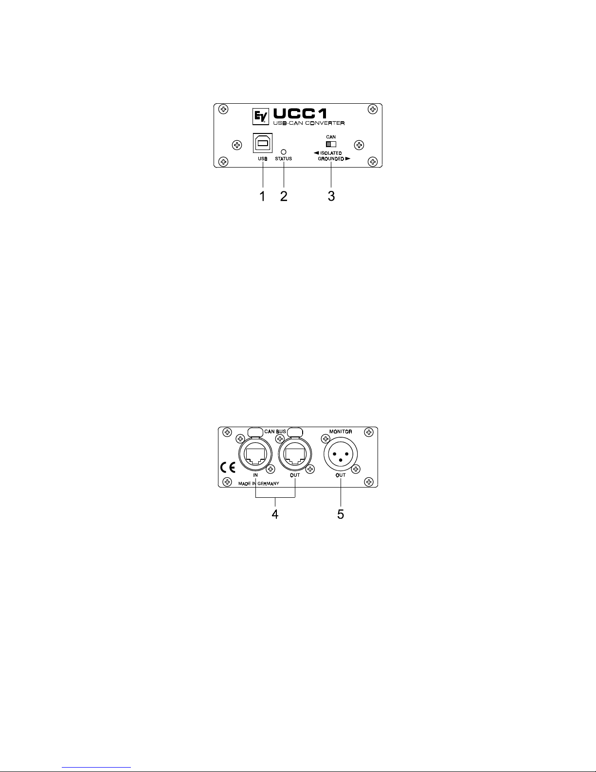
2. Controls and Connections
Fig. 1: UCC1 front panel
1. USB connector
This connector is for the connection to the USB-port on your PC. The interface complies with the
USB 1.1 specifications and offers data transfer as well as operation voltage supply for the UCC1.
2. STATUS indicator
The STATUS LED indicates the actual operational state of the UCC1. The indicator lights when
the UCC1 has been connected to the PC, the dedicated driver software has been installed, and the
PC has recognized the unit. The LED blinks during data accesses.
3. CAN ISOLATED / GROUNDED switch
Setting this switch to ISOLATED galvanically isolates the CAN-port of the UCC1 from the rest of
the circuitry, effectively eliminating ground-loop interference noise. Setting the switch to
GROUNDED galvanically connects the CAN-bus to the USB-port ground and thus to the PC.
Fig 2: UCC1 rear view
4. CAN BUS IN / OUT connectors
These two sockets are for connecting EV-appliances that are furnished with serial CAN-bus. Both
connectors are connected in parallel for convenient carrying through CAN-bus data.
5. MONITOR connector
The MONITOR connector provides audio signal output for the monitor bus of EV P-Series
Remote Amps. The monitor bus allows listening to the audio signal of any amplifier within the
system, without the need for additional wiring.

19
3. Installation
3.1 Unpacking
The UCC1 package includes the following parts:
1 UCC1 USB-CAN CONVERTER
1 Front panel 19“, 1HU
2 CAN-TERM 120 Ω CAN-bus terminator-plug
4 Rubber feet
1 USB cable
1 Owner’s manual
Upon receiving your UCC1, please inspect the contents of the package for loss or damage. If any of
the here listed parts are missing or damaged, please immediately contact your distributor or a TELEX /
EVI Audio service center.
3.2 Rack-Mounting
The compact UCC1 adapter is mainly aimed for connection to a laptop or notebook computer.
However, the supplied 19“ front panel allows trouble-free integration in a rack shelf system. For
mounting the 19“ front panel, please proceed as follows:
1. Loosen the two center screws on the UCC1’s panel (1).
2. Loosen the four corner screws on the UCC1’s panel (2).
3. Remove the original UCC1 panel (3).
Fig. 3: Exchanging UCC1 front panels
4. Fix the 19“ front panel on the UCC1. In doing so, make sure not to damage, bend or stress the
STATUS indicator and the ISOLATED / GROUNDED switch. (4).
5. Reinsert and tighten the two center screws of the UCC1 19“ panel (5).
6. Reinsert and tighten the four corner screws of the UCC1 enclosure (6).
Now you are able to install the UCC1 in a rack shelf system securing it with the four rack-screws on
the sides.
 Loading...