

Electrothermal ATS11005 Instruction Manual

STEM ‘INTEGRITY’ Control Instruction Book.
(PC Control reaction Station Software).
Page 1 of 86 Integrity Control Instruction Book M8162 Issue 2.1

Please take your time to read this Instructions book in order to understand the safe and correct
Section
Title
Page
1.
Introduction.
5
2.
Symbols and using the Instruction Book
6
3.
Safety Information for using your INTEGRITY product.
7
4.
Unpack and contents.
9
5.
Minimum P.C. Specification
10
6.
‘INTEGRITY’ Installation
11
7.
Environmental Protection.
12
8.
‘INTEGRITY’ Windows service
13
9.
‘INTEGRITY’ Dongle key
13
10.
‘INTEGRITY’ Client
14
10.1.
The User Interface
14
10.1.1.
Main Menu and Tool Bar
14
10.1.2.
Status Bar
15
10.1.3.
Primary Navigation Buttons
15
10.1.4.
Reaction Station Status Panel
15
10.1.5.
Logging In.
17
10.1.6.
Locking User Interface
17
11.
Managing Users
19
11.1.
Add, Modify and Delete users.
19
11.2.
Change Password of current user.
21
12.
Recipe Management
23
12.1.
Add, Modify or delete Recipe
23
13.
Hardware.
26
13.1.
Hardware View
26
13.2.
Instrument Information Screen
27
13.2.1.
Multiplexer Information.
27
13.2.2.
Reaction Station Information.
28
13.2.3.
Multi Temp Information.
38
13.2.4.
Multi IR Information.
39
13.3.
Monitoring and Recording real time data from hardware.
41
13.3.1.
Adding Channels for Monitoring.
42
13.3.2
Viewing pre-recorded data.
43
14.
Defining and loading experiments
44
14.1.
Experiment setup.
44
14.2.
Loading an experiment.
51
14.3.
Managing temperature, stirrer speed and user action settings
of an experiment
53
14.3.1
Managing temperature Settings
53
use of your new Bibby Scientific ‘INTEGRITY’ software.
It is recommended the Responsible Body for use of this equipment reads this Instruction
book and ensures the user(s) are suitably trained in its operation before using it with Bibby
Scientific product.
Table of Contents.
Page 2 of 86 Integrity Control Instruction Book M8162 Issue 2.1

14.3.2
Managing the Stirrer Setting
57
14.3.3.
Managing the User Actions
57
14.4.
Adding a Note.
61
14.5
Copying and pasting an Experiment.
62
14.6
View My view
63
15.
Running an Experiment
64
16.
Experiment Results.
67
16.1.
Viewing the Experiment results.
67
16.2.
Loading Experiment Results
68
16.3.
Viewing “My view”.
70
16.4.
Importing Experiment Results.
71
16.5.
Exporting Experiment Results.
71
16.6.
Exporting Experiment Results to Excel
72
16.7
Deleting Experiment Results
73
17.
Dissolution and Solubility Curve.
73
17.1.
Creating a new solubility curve
74
17.2.
Loading a solubility curve.
75
17.3.
Other Functionalities of the solubility curve.
76
18.
General Settings.
78
18.1.
Settings.
78
19.
Closing the application.
79
20.
Customer Support.
80
21.
CFR 21 Part 11 Compliance
82
22.
Notes.
83
23.
Distribution Information.
86
Appendix ‘A’
Integrated System Connection.
81
To Setup and use your Integrity Reaction Station please refer to Instruction book supplied
with the product.
Page 3 of 86 Integrity Control Instruction Book M8162 Issue 2.1

© The copyright of this instruction book is the property of Bibby Scientific Limited. This instruction book is supplied
Bibby Scientific Limited.
Beacon Road,
Stone,
Staffordshire ST15 0SA,
Great Britain.
Tel: +44(0)1785 812121
Fax: +44(0)1785 810405
General enquiries :
info@bibby-scientific.com
Order enquiries :
sales@bibby-scientific.com
Technical support :
electrothermalhelp@bibbyscientific.com
www.electrothermal.com
For the America’s and Canada, contact:
Techne Incorporated, 3 Terri Lane,
Suite 10 Burlington, NJ 08016 USA.
Toll free:800-225-9243Tel: 609-589-2560
Fax: 609-589-2571
Email: labproducts@techneusa.com
Http www.techneusa.com
by Bibby Scientific Limited on the express understanding that it is to be used solely for the purpose for which it is
supplied. It may not be copied, used or disclosed to others in whole or part for any purpose except as authorised
in writing by Bibby Scientific Limited. Bibby Scientific Limited reserves the right to alter, change or modify this
document without prior notification.
In the interest of continued development Bibby Scientific Limited reserve the right to alter or modify
the design and /or assembly process of their products without prior notification.
This product is manufactured in Great Britian by Electrothermal, part of the Bibby Scientific Group of
companies.
Page 4 of 86 Integrity Control Instruction Book M8162 Issue 2.1

1. INTRODUCTION.
1.1. ‘INTEGRITY’ is a professionally advanced application which represents a true milestone in
Integrity Reaction Station control. With an incredibly ‘user friendly’ interface, this software
makes your Integrity a truly evolutionary workhorse providing accuracy in all aspects of
temperature and stirring control, whether you are working with solubility, crystallisation or
chemical reaction, results can be saved and stored and together with many technological
features such as the ‘Solubility curve generator’ and, state of the art Import / Export
functions, this application will advance your laboratory processes for many years.
1.2. Additional accessories which customise your Integrity processes are fully supported such
as Infra Red probe for particle measurement and Multi Temp for contents temperature
control. The platform has been laid down to support and integrate future accessories as
they evolve ensuring your processes benefit from all the latest technological advances as
they happen.
1.3. Experiment data features include the facility to show boiling points, calculations, and a
solvent list, while a scheduler allows for batch control parameter setting. Solubility
functions include a profile generator and the calculation of curves from the temperature
steps from initial data. Further more, this application supports the creation of solubility /
crystallisation profiles which are enhanced with the ability to control syringe pumps which
automatically change concentration.
1.4. While an experiment is running you have the ability to pause and / or edit a profile during a
run. The facility exists to have multiple users when cell positions are vacant. You may view
real time data, both as a raw file or in graphical format. An emergency stop function is
provided for that quick system shut down for those accidental moments and a cell lock
feature is provided to prevent a running experiment from being disrupted while setting up
another cell.
Page 5 of 86 Integrity Control Instruction Book M8162 Issue 2.1
2. SYMBOLS AND USING THIS INSTRUCTION BOOK
Caution. See note or adjacent symbol.
Caution / risk of electric shock
Recyclable Packing Material
Do not dispose of product in normal domestic
waste.
Caution. Hot surface.
Refer to Operator Instructions book.
Bio Chemical Hazard. Caution required. Will
require decontamination.
2.1. Throughout this Instruction book and on you Integrity product the following symbols are
shown to identify conditions which pose a hazard to the user or to identify actions that
should be observed. These symbols are also shown on the product, or its packaging.
When a symbol is shown next to a paragraph or statement it is recommended the user
takes particular note of that instruction in order to prevent damage to the equipment or to
prevent injury to one’s self or other people.
The Responsible Body and the Operator should read and be familiar with this
Instructions book in order preserve the protection afforded by the equipment.
To prevent injury or equipment damage it is the manufacturer’s recommendation
that all persons using this equipment are suitably trained before use.
2.2. Symbols defined.
‘INTEGRITY’ Application Symbols.
Page 6 of 86 Integrity Control Instruction Book M8162 Issue 2.1

3. SAFETY INFORMATION FOR USING YOUR INTEGRITY PRODUCT.
To prevent a risk of fire or electric shock, DO NOT open the
Integrity or PSU case without authorisation. Only qualified Service
personnel should attempt to repair this product
Ensure the Mains Power Supply conforms to rating found on the
data plate located on the side of the PSU.
Never Operate Integrity equipment without connection to earth /
ground. Ensure the mains supply voltage is correctly earthed /
grounded in accordance with current area legislation.
“Always follow good laboratory practice when using this equipment.
Give due recognition to current health and safety legislation
(including Guidelines and Approved Codes of Practice), your
company’s health and safety procedures and all other associated
legislation / regulatory requirements applicable to your areas of
operation.
Check laboratory procedures for substances being heated and
ensure all hazards (e.g. explosion, implosion or the release of
toxic or flammable gases) that might arise have been suitably
addressed before proceeding. When heating certain substances the
liberation of hazardous gases may require the use of a fume
cupboard or other means of extraction.
Ensure equipment is used on a clean, dry, non-combustible, solid
work surface with at least 300mm suitable clearance all around
from other equipment.
Ensure the PSU is positioned on a clean, dry, non-combustible
surface with a sufficient space for the power cable to Integrity and
mains input lead and plug set to enter / exit without undue bend
stresses. Ensure a suitable clearance for air flow and heat
dissipation.
Do not position the Integrity so that it is difficult to connect /
disconnect from the power cable assembly.
Do not position the Integrity so that it is difficult to connect /
disconnect from the coolant fluid supply.
Do not position the Integrity so that it is difficult to connect /
disconnect data and communication cables.
Do not position the PSU so that the on / off switch is inaccessible.
Do not immerse any part of this equipment in water / fluid.
Do not spill substances onto this product. If spillage does occur,
disconnect unit from mains supply and follow instructions as
detailed in Section ‘Maintenance’.
3.1. This product has been designed for safe operation when used as detailed in accordance
with the Manufacturer’s instructions.
NOTE: Failure to use this equipment in accordance with the manufactures operating
instructions may compromise your basic safety protection afforded by the equipment and
may invalidate the warranty / guarantee. The warranty / guarantee does not cover damaged
caused by faulty installation or misuse of the equipment.
3.2. Prevention of Fire and Electric Shock.
3.3. General Safe Operating Practice.
Page 7 of 86 Integrity Control Instruction Book M8162 Issue 2.1

Do not cover the Integrity or PSU whilst in use.
It is not recommended to leave any heating apparatus unattended
during operation.
The equipment is not spark, flame or explosion proof and has not
been designed for use in hazardous areas in terms of BSEN 6007914:1997. Keep flammable, low flash point substances away from
the apparatus.
Do not operate or handle any part of this product with wet hands.
Do not touch the heating surface whilst in use.
Do not lean or stretch over equipment.
surface.
Caution! : Always ensure that when using an external probe for
temperature control that it is correctly located in the required cell
position before starting a programmed run.
Page 8 of 86 Integrity Control Instruction Book M8162 Issue 2.1

4. UNPACKING. (‘INTEGRITY’ Application).
For your future reference please record your
‘INTEGRITY’ Licence number.
‘INTEGRITY’ Licence Number.
Item
Description
Qty
1 Instruction Book (M7979)
1
2
Warranty registration card.
1
3
Application Software CD
1
4
‘INTEGRITY’ Dongle Key
1
Please Note:
By opening this box and breaking the security seal you have accepted the contents of this
package. Bibby Scientific will not accept this product by way of return unless it is faulty.
This does not affect your statutory rights under country specific law.
4.1. Please check the contents of your package.
Please fill out the Warranty registration card and post it to Bibby Scientific.
See section 20. Customer Support.
Please write the product serial number on the Integrity Dongle key fob.
Page 9 of 86 Integrity Control Instruction Book M8162 Issue 2.1

Processor
Pentium 4 or above.
RAM
500MB or above.
App Disk Space
200MB or above
Disk Space
30 GB or above
Graphics Card
64 MB or above
Screen Resolution
1024 x 768 or greater.
CD Rom Drive
To load application
USB connectivity.
To support Hardware Key
RS232 / 485 port / USB
Connection for INTEGRITY
Reaction Station.
5. MINIMUM PC SPECIFICATION.
The minimum P.C. Hardware requirements recommended for this application are as follows:
In addition the PC must host Windows XP Service Pack 2 or above
Page 10 of 86 Integrity Control Instruction Book M8162 Issue 2.1
6. INTEGRITY PC SOFTWARE INSTALLATION.
Note: Before installation of ‘INTEGRITY’ ensure Microsoft net framework 2.0 or above is
set up on your computer.
Ensure all previous versions of ‘INTEGRITY’ software via the ‘add or remove software’
function in control panel have been uninstalled and deleted.
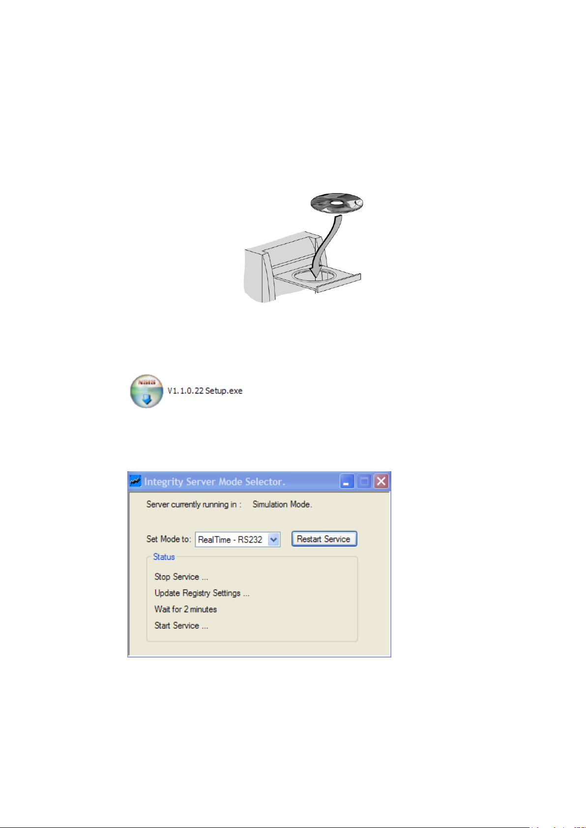
Insert CD into PC.
(P.C. illustration for guide only).
6.1. By running the setup program (icon below) the software will scan the PC’s
requirements and automatically install the required programs to run the
Software.
6.2. Once setup is complete go to Start\All Programs\Integrity\Server Mode
Switching Utility, select the desired communications method and restart
service. When this has finished, close the window.
6.3. Go to Start\All Programs\Integrity\Integrity client and run the software.
Page 11 of 86 Integrity Control Instruction Book M8162 Issue 2.1

7. ENVIRONMENTAL PROTECTION.
7.1. Maximum consideration has been given to environmental issues within the design and
manufacturing process without compromising end product performance and value.
7.2. Packaging materials have been selected such that they may be sorted for recycling.
Page 12 of 86 Integrity Control Instruction Book M8162 Issue 2.1
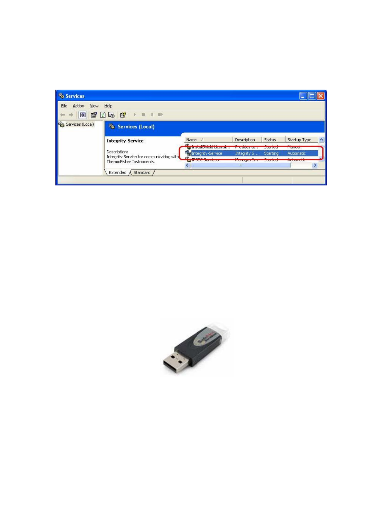
8. ‘INTEGRITY’ WINDOWS SERVICE.
In order for the ‘INTEGRITY’ to run, the ‘INTEGRITY’-Service must be running on the target PC.
All communication to the attached devices are carried out by the ‘INTEGRITY’ Client through the
‘INTEGRITY’ Server.
9. ‘INTEGRITY’ HARDWARE KEY.
Please ensure that the Hardware Key (provided to you along with the ‘INTEGRITY’ software) is
securely connected to your PC’s USB Port before you start the ‘INTEGRITY’ UI.
Page 13 of 86 Integrity Control Instruction Book M8162 Issue 2.1
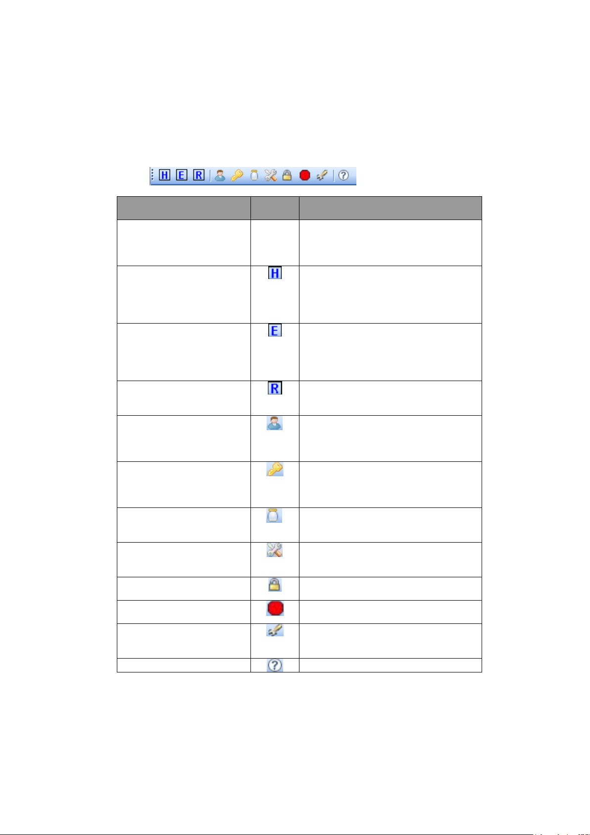
10. ‘INTEGRITY’ CLIENT.
Main Menu Item
Tool
Item
Description
File >> exit
None
Close the ‘INTEGRITY’ Client. Note:
the client will not close if there are
running Experiments for this client.
View >> hardware
Displays the “Hardware” section in the
main right pane. This option is disabled
if the UI fails to connect to the server
or is working in offline mode
View >> Experiment
Displays the “Experiments” section in
the main right pane. This option is
disabled if the UI fails to connect to the
server or is working in offline mode
View >> Results
Display the “Results” section in the
main right pane.
Tools >> User Management
Launches the “Change Password”
pop-up screen for the currently logged
in user.
Tools >> Change Password
Launches the “Change Password”
pop-up screen for the currently logged
in user
Tools >> Recipe
Management
Launches the “management Recipe”
pop-up screen.
Tools >> Manual Control
Launches the “RS Cell Info” screen if
there is a connected Reaction Station.
Tools >> Lock
Locks the current UI instance.
Tools >> Abort All
Aborts all running Experiments, if any.
Tools >> Settings
Launches the Application Setting popup.
Help >> About RSPC-S
Displays the “About Dialog”.
10.1. The User Interface
10.1.1. The Main menu and Tool Bar
The ‘INTEGRITY’ Client has the standard tool bar as shown in the figure below.
Page 14 of 86 Integrity Control Instruction Book M8162 Issue 2.1
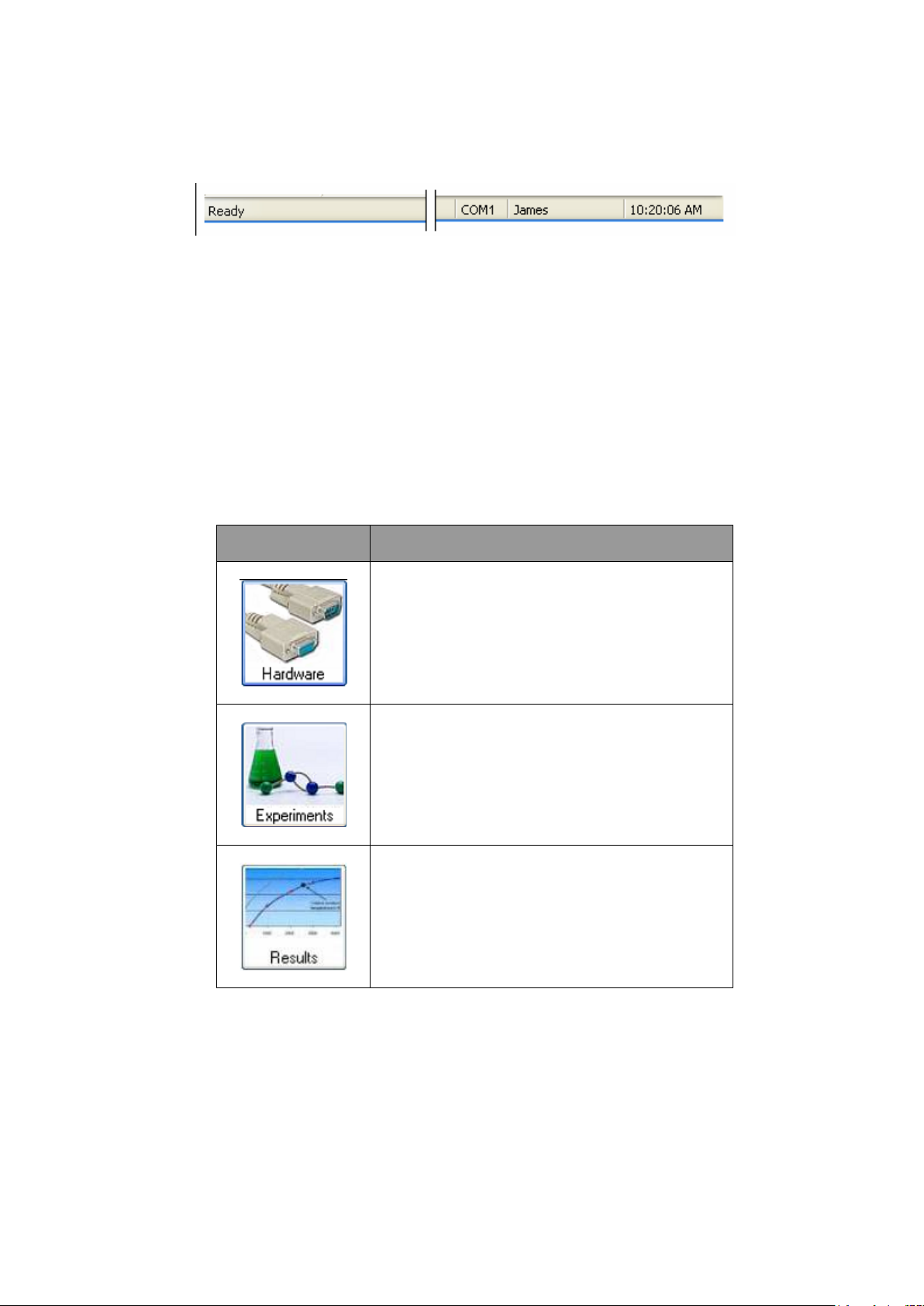
10.1.2. Status Bar.
Primary
Navigation Button
Description
Displays the ‘Hardware’ section in the main right
pane. The option is disabled if the UI fails to
connect to the server or is working in offline mode.
Displays the ‘Experiments’ selected in the main
right pane. This option is disabled f the UI fails to
connect to the server or is working in offline mode.
Displays the ‘Results’ section in the main right
pane.
The ‘INTEGRITY’ Client has the standard status bar as shown in the figure below.
‘INTEGRITY’ User Guide.
Going from Left to Right, it displays the following information.
Application Status.
Active COM Port for the UI session.
Current Logged in User ID.
Current System Time.
10.1.3. Primary Navigation Buttons.
The following figure shows the primary navigation buttons of the ‘INTEGRITY’ application.
10.1.4. Reaction Station Status Panel.
If a reaction status is connected to the target COM port, the ‘INTEGRITY’ Client displays a Reaction
Station panel in the “Hardware” and “Experiments” screen which gives a quick snapshot of the
status of each Reaction Station Cell. To accommodate more information into the status panel, each
cell has two views. The first view primarily displays the Experiment status and Accessories
available for that cell in an iconic form, while the second view displays the actual reading from the
accessory probes. The Block Temperature and the Stirrer speed are displayed in both views.
Page 15 of 86 Integrity Control Instruction Book M8162 Issue 2.1
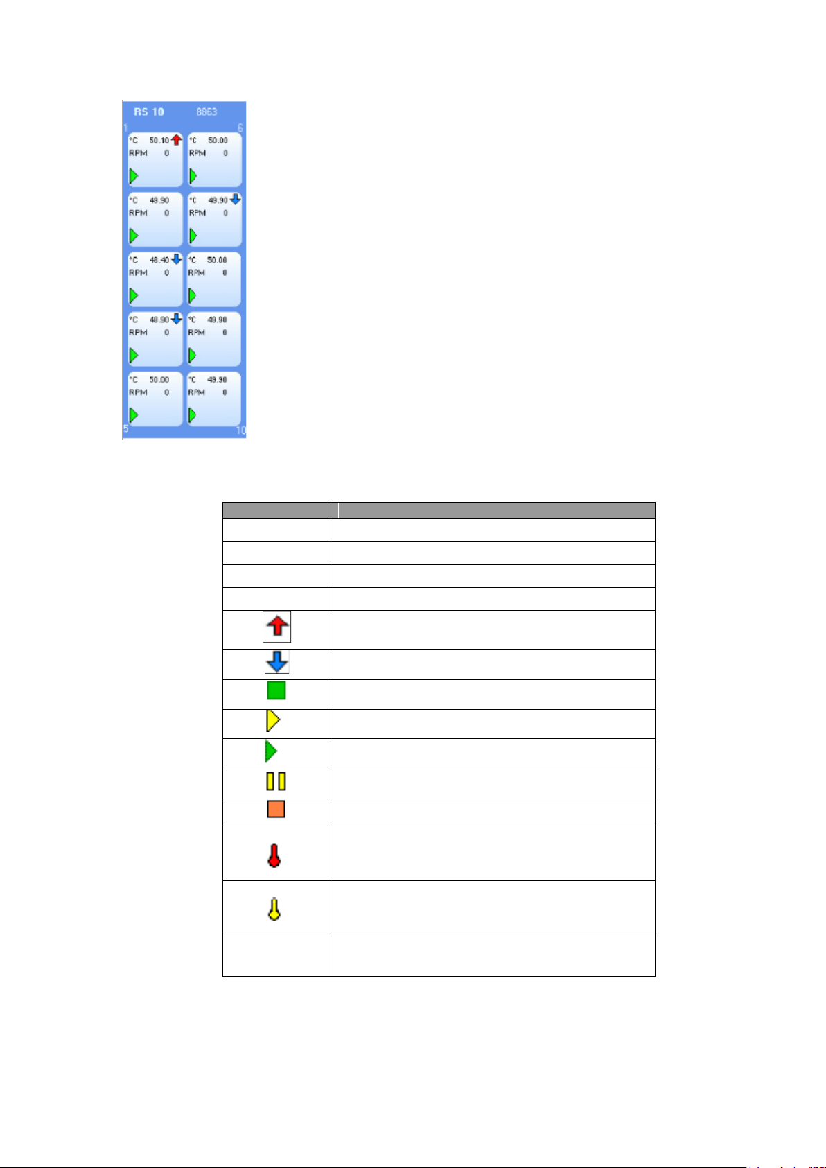
◄RS10 Status Panel
Field Name
Description
C
Block Temperature.
RPM
Stirrer Speed.
PrC
Probe Temperature (2)
IR
IR Reading (2)
Indicates increase since last reading.
Indicates decrease since last reading.
Experiment loaded but not running (1)
Experiment in Pre-Heat stage (1)
Experiment is running temperature profiles (1)
Experiment paused (1)
Experiment Finished (1)
A Multi Temp unit is connected to the RS’s AUX
port, and its probe is assigned to the cell in
‘Contents Control’ mode. (1)
A Multi Temp unit is connected to the RS’s AUX
port or through Multiplexer, and its probe is
assigned to the cell without ‘Contents Control’.(1)
Heat Ex
Heat Exchange Temperature.
The table below describes the various indicators used in the Status Panel Cell.
(1) Items displayed in View 1 only.
(2) Items displayed in View 2 only.
Page 16 of 86 Integrity Control Instruction Book M8162 Issue 2.1
Note: NA (Not Available) is displayed if the application fails to read the specific reading.
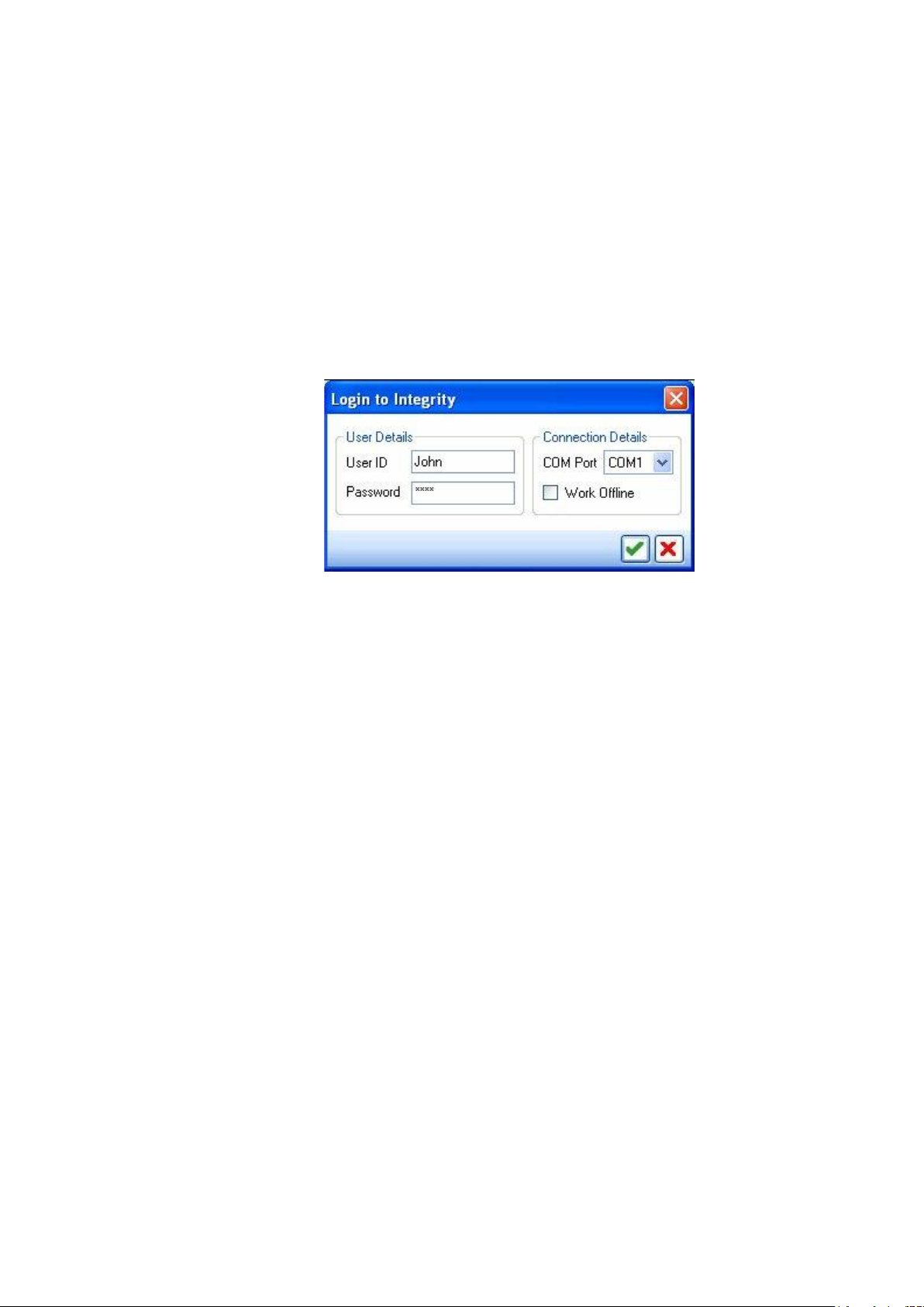
10.1.5. Logged In.
To log into the ‘INTEGRITY’ Client, perform the following actions:
1. From the windows Start button, click on Programs >> Electrothermal>>
RSPC-S Client.
2. To log into the application, enter a valid user name and password.
User ID is “admin”
Password is “rspc-s”
If recognised devices are connected to multiple COM Ports, then the COM ports will be
3.
listed in the ‘COM Port’ drop down. Select the COM port of your choice from the list, or
select ‘Work offline’.
Note: If the server fails to detect any recognised device in any of the COM Ports, the
COM Port list box will be disabled and automatically the ‘Work Offline’ mode will be
selected.
10.1.6. Locking User Interface.
Lock feature allows the user to lock the user interface of the ‘INTEGRITY’ application. Once
the user interface is locked, no other operations are allowed unless the user unlocks it.
User interface is unlocked using the user’s login password.
Page 17 of 86 Integrity Control Instruction Book M8162 Issue 2.1
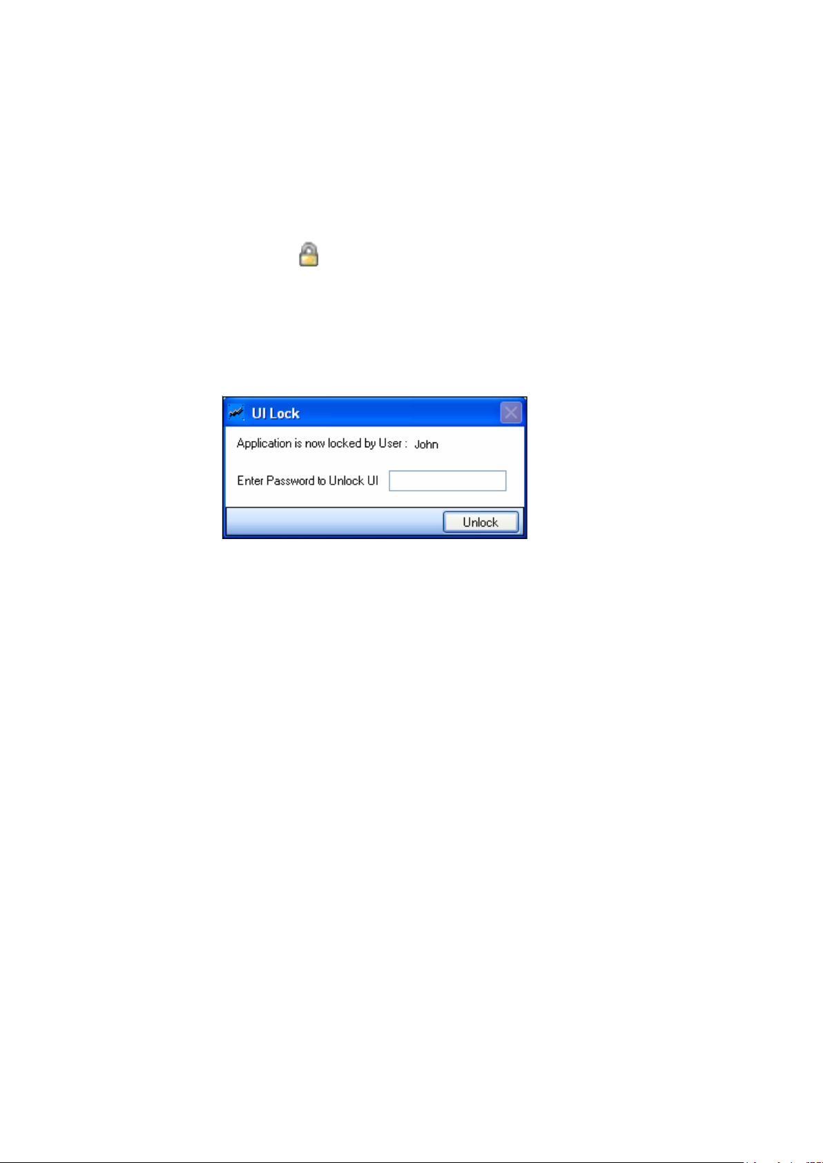
To Lock the User Interface.
1. From the Main menu, select the ‘Tools >> Lock’ option.
Or
Click on the icon on the Tool Bar.
2. The ‘UI Lock’ window appears.
3. User interface is locked. Enter the password and click ‘Unlock’ to unlock the user
interface.
Page 18 of 86 Integrity Control Instruction Book M8162 Issue 2.1
11. MANAGING USERS.
In this section the user is permitted to add and manage other users. The main features of this
module are:
Addition of |New users to the ‘INTEGRITY’ application.
Deletion of existing users from the ‘INTEGRITY’ application.
Managing access rights of users.
11.1. Add, Modify or Delete users.
To add a new User.
1. From the main Menu, select the ‘Tools >> User Management’ option.
Or
Click on the icon in the Tool Bar.
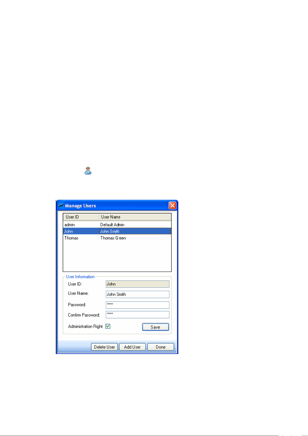
2. The ‘Manage User’ window appears.
Page 19 of 86 Integrity Control Instruction Book M8162 Issue 2.1

The top half of this screen displays the list of existing Users. The details of the selected user can be
Field Name
Description
User ID
User has to input User ID in this field.
User name
Displays the User name of the selected user.
This field is editable.
Password
Displays the Password of he selected user.
This field is editable.
Confirm Password.
Displays the password of the selected user.
This field is editable.
Administration Rights
Select ‘Administration Rights’ option to give
administration privileges to the user.
Save
Saves the user details created from the
application.
Delete User.
Deletes the selected user from the
application.
Add User.
Adds a new user to the application.
Done.
Click this to close the ‘User Manager’.
viewed or edited in the User Information section in the lower half of the screen.
The following table gives the details of the attributes on the Manage Users screen.
3. To add a ‘new user’, click Add User and enter the following details in the User
Information section.
User ID
User Name
Password
Confirm Password
Administration Right.
4. Click ‘Save’ to store the new user information into the ‘INTEGRITY’ application.
To modify an existing User.
1. Select the user you wish to modify from the User List. This will display the user’s
details in the User Information section.
2. Modify the following details in the User Information section:
User Name
Password
Confirm Password.
Page 20 of 86 Integrity Control Instruction Book M8162 Issue 2.1
3. Click ‘Save’ to store the modified user information.
Note: Users with an administration right can add, delete and modify the attributes of
another user. If the administration rights are not given to the user the user can only
change the password. Select the Administration rights option if you want to give
administration privileges to the user.
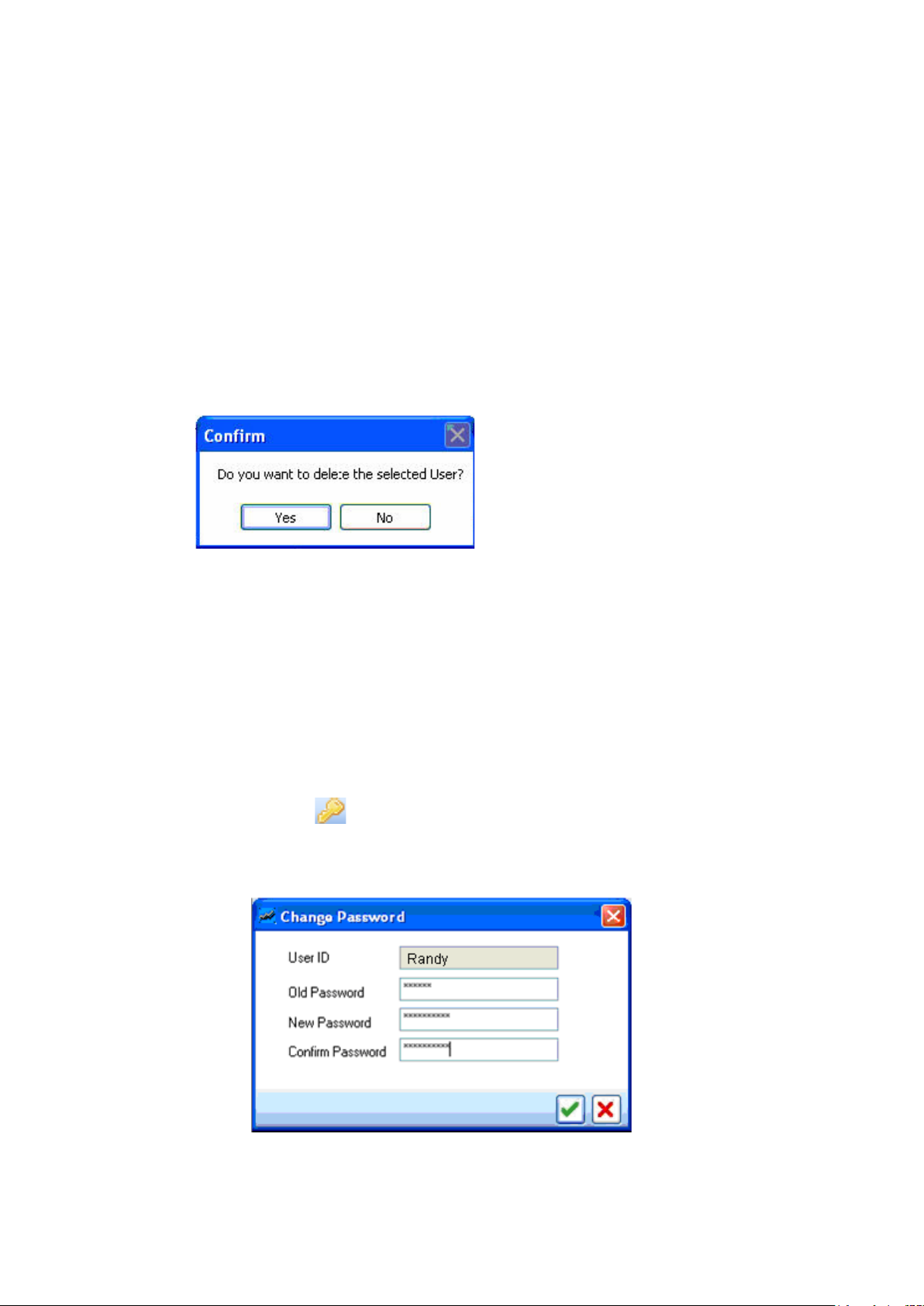
To Delete an Existing User.
1. Select the ‘User’ you wish to delete from the User List.
2. Click ‘Delete User’ in the Manager window. The following warning will be displayed.
3. Click ‘Yes’ to delete the user permanently from the ‘INTEGRITY’ application.
11.2. Change Password of Current User.
To Change the Password of the Current User.
1. From the main menu, select the Tools >> Change Password option.
Or
Click the icon in the Tool Bar.
2. The Change Password window appears which displays the User ID of the logged in
user.
3. Type the Old Password in the ‘Old Password’ Field.
Page 21 of 86 Integrity Control Instruction Book M8162 Issue 2.1

4. Type the New Password in the ‘New Password’ field and confirm the new password
in the ‘Confirm Password field’.
5. Click for accepting the change in the Password.
Page 22 of 86 Integrity Control Instruction Book M8162 Issue 2.1
12. RECIPE MANAGEMENT.
Recipe Management allows the user to add new recipes and delete or modify existing recipes.
Recipe details of various samples used for running experiments can be pre-defined using this
screen, and can be used to link them during defining Experiments.
12.1. Add, Modify or Delete a Recipe.
To add a new Recipe.
1. From the Main menu, select the Tools >> Recipe Management option.
Or
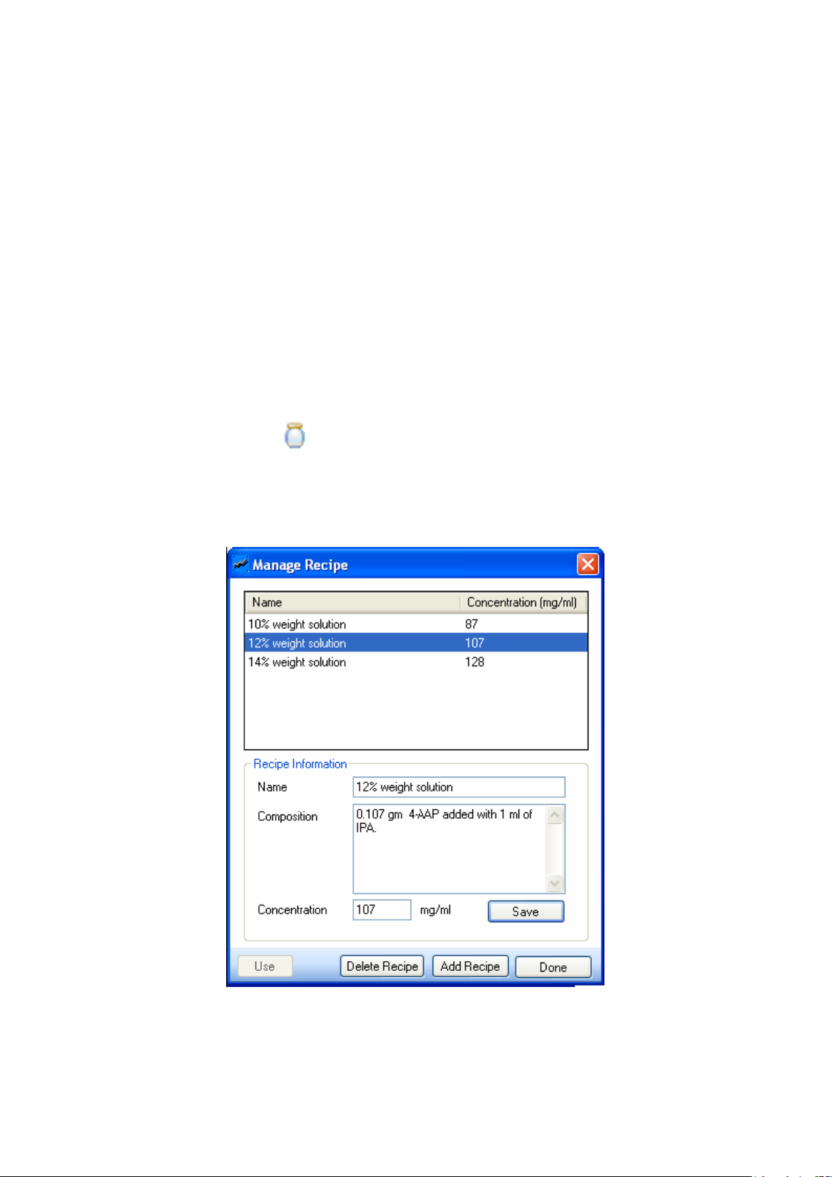
Click the icon in the Tool Bar.
2. The Manage Recipe window appears.
Page 23 of 86 Integrity Control Instruction Book M8162 Issue 2.1

The top half of this screen displays the list of existing Recipes. The details of the selected recipe
Field Name
Description
Name
Displays the recipe name.
Composition
Displays recipe composition. Enter any free
format textual display of the composition in
this field.
Concentration
(mg/ml)
Displays the concentration of the recipe
used.
Save
Saves the changes done.
Used
Enabled only when this is invoked from the
Experiment wizard screen.
Delete Recipe
Deletes the selected recipe.
Add recipe
Clears the recipe information of the
previously selected recipe and allows the
user to add new recipes.
Done
Closes the Manage screen.
can be viewed and edited in the Recipe Information section in the lower half of the screen.
The attributes in the Manage Recipe screen are explained in the below table.
3. Click ‘Add Recipe’ and enter the following details:
Name
Composition
Concentration.
4. Click Save to store the new recipe information into the ‘INTEGRITY’ application.
To Modify an Existing Recipe.
1. Select an existing recipe from the Recipe List. Its details will be displayed in the
recipe Information section.
2. Modify the following details in the Recipe Information section:
Name.
Composition.
Concentration.
3. Click save, to store the modified recipe information.
4. To delete existing users, click delete User in the manage Recipe window and the
following warning is displayed.
Page 24 of 86 Integrity Control Instruction Book M8162 Issue 2.1

5. Click ‘Yes’ to delete the recipe permanently from the ‘INTEGRITY’ application.
Page 25 of 86 Integrity Control Instruction Book M8162 Issue 2.1
13. HARDWARE
13.1. Hardware View.
The hardware module is one of the main components of the ‘INTEGRITY’ application. In this
section the RSCS application displays the hardware detected in the target COM Port. The main
objectives of the module are:
To detect if hardware components are connected to the PC when the RSPC application
is running.
To display the different views of the hardware components.
To monitor the attributes of individual hardware components.
To control individual hardware components.
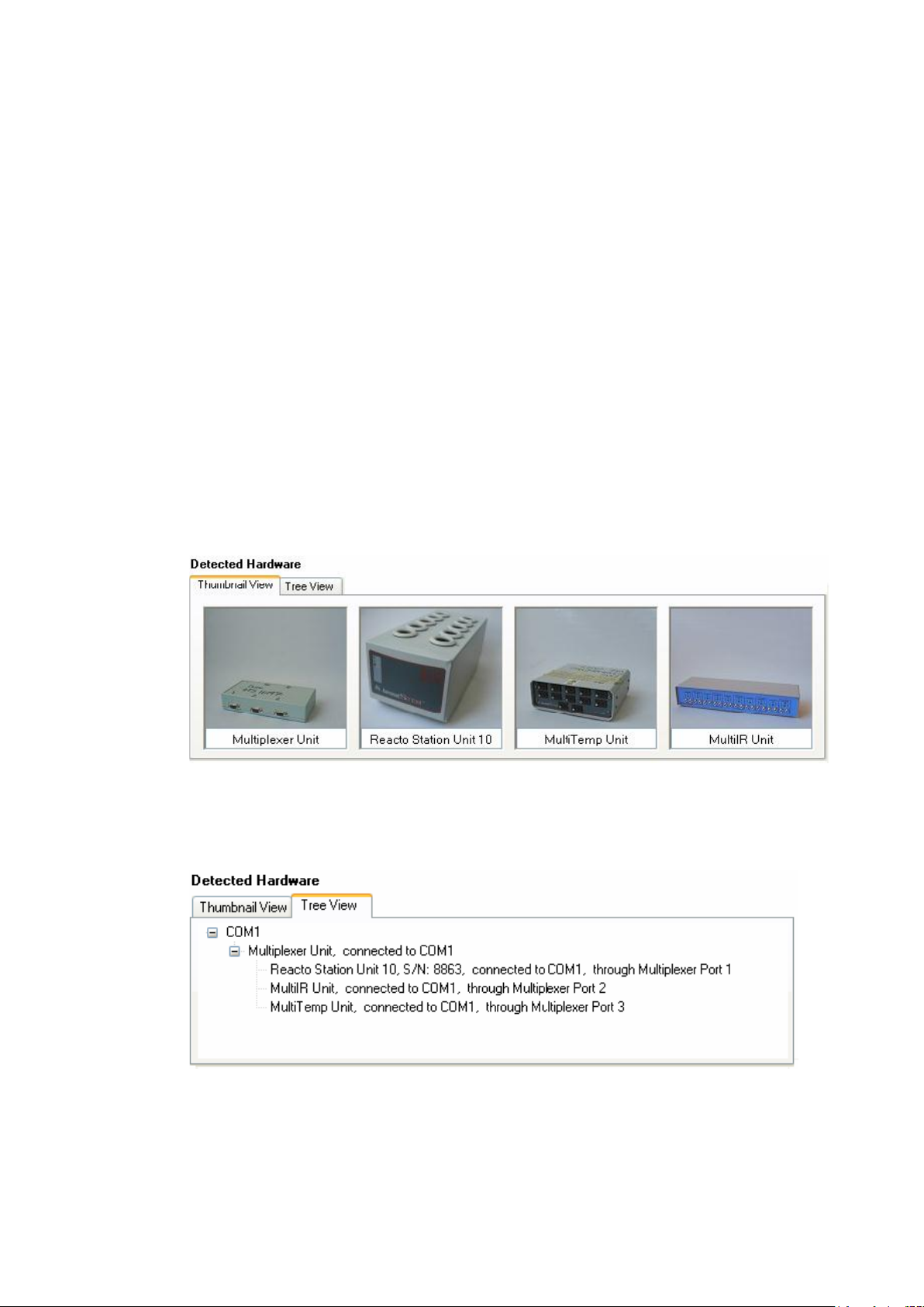
By clicking on the following tab’s the detected hardware can be viewed in one of two ways:
Thumbnail View: This view displays thumbnail images of the detected hardware
components.
Tree View: The tree view displays a tree of the detected components, as shown in the
following figure.
Note: Both the icon view and the tree view gives a list of all the hardware components
connected to the active port of the ‘INTEGRITY’ UI session.
Page 26 of 86 Integrity Control Instruction Book M8162 Issue 2.1
 Loading...