

Electroswitch 25-1000 Operation Manual
180 King Avenue, Weymouth MA 02188 Tel: 781-335-5200 www.Electroswitch.com
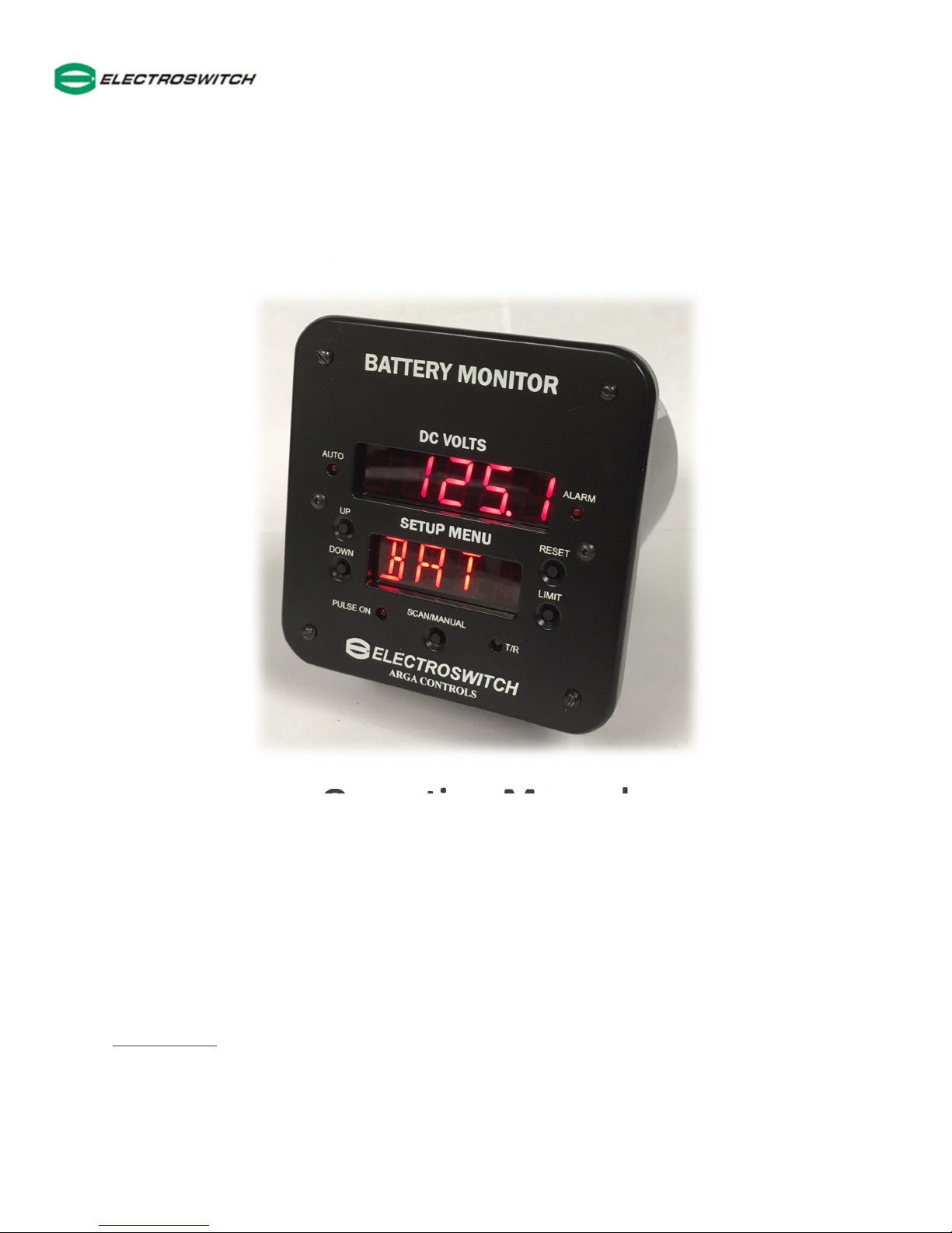
25-1000 Battery Monitor
Operation Manual
COMPLIANCE
ANSI (IEEE) C37.90.1 [Surge Withstand]
IEC 61000-4-3 [EMC]
DNP3 Self Certified to Level I
25-1000-UM
Battery Monitor Operation Manual

Table of Contents
Product Overview….………………………………………………………………………………….………… 3
Specification…………………………………………………………………………………….…………………. 4, 5
Control Panel Description…………….………………….......…………………………………..……….. 6
Alarms and Parameters – Change / View……………............…………………………………… 7-9
Operational Flow Diagram…………………………………………………………………….……………. 10
Serial Communications………………………………………………………………………………………. 11-14
Terminal Block wiriing and Annunciator output Connector J1………………..…………… 15
Typical Wiring Diagram……….……………………………………………………………………………… 16
Mechanical Dimensions……………………….…………………………….………………………………. 17
25-1000-UM 2

Product Overview
The Electroswitch 25-1000 panel mount Battery Monitor is a breakthrough in battery
monitoring and ground fault detection. This highly accurate panel mount instrument is
powered by the same battery it monitors. It displays charging voltage, ripple voltage,
ripple current (with optional current probe, 25-1100-H1) positive/negative ground faults
and high impedance faults based on ripple voltage and ripple current.
The alarm outputs are designed with form C relay contacts and can indicate +bus / -bus
leakage, ground shorts, over/under voltage, high ripple voltage, low ripple current, loss
of AC voltage to the charger and high impedance due to corrosion buildup.
Also included, an additional feature that generates a pulse through the ground fault path
enabling the operator to locate the exact location of the short circuit using the optional
model 25-1100-GF handheld ground fault detector.
All alarm set points and system functions are stored in on-board non-volatile memory
and will not be lost even when power goes down. Fail safe operation is provided by relay
contact when power is lost. The instrument also provides a time delay alarm feature
that allows the operator to delay alarms up to 60 seconds preventing false alarm
indications. The 25-1000 Battery Monitor supports DNP3 or Modbus serial
communication protocols over a RS-485 data line. Industry standard baud rates up to
19.2K. Additionally the instrument provides 4-20mA or 0-1mA analog outputs.
25-1000-UM 3

25-1000 Battery Monitor Specifications
1. Display Readout: 4 ½ digits red numeric LED’s, plus four 14-segment alpha-numeric LED annotation and
configuration digits
2. Battery/Input Voltage Range: 90 to 180 VDC, Accuracy: ± 0.2V DC (for 125 V model)
3. Input Power: 3 VA
max
4. Input Resistance:
Positive terminal to ground: 30.82 K Ohms, ± 1%
Negative terminal to ground: 30.82 K Ohms, ± 1%
5. Displayed Measurements:
a. Battery Voltage
b. + Bus voltage to Ground
c.
-
Bus voltage to Ground
d. GFV - Ground Fault Voltage
e. RVV - Ripple Voltage
f. RIV - Ripple Current (w/optional sensor)
6. Displayed Modes:
a. TD - Time Delay (Sec)
b. 1φ or 3φ - Charger Input Power Phase
7. Scanning: In Manual Mode, measurement is selected by briefly pushing the scan/select button.
In Scan Mode (Auto LED ON) the display cycles through all six measurements, plus time delay and AC
charger phase. Mode is changed by pressing and holding the scan button
8. Alarms: Alarm levels are set using the setup menu
9. Alarm relay form C Contacts:
Relay 1: + Ground Fault
Relay 2: - Ground Fault
Relay 3: High Battery Voltage
Relay 4: Low Battery Voltage, ripple voltage, ripple current, loss of AC power to charger
10. Time Delay: Alarm delay configurable from 1 to 60 seconds
11. Reset (Alarm relay reset): In non-Latching Mode (L OFF) the alarm relay contact clears automatically
(after the time delay period) when the fault condition is cleared. In Latching Mode (L ON) the alarm relay
latches on. To reset the alarm relay, the fault condition must be removed. Then pressing the RESET button
or shorting RESET pin TB2-20 to BAT- pin TB1-4 (negative bus) will reset the alarm relay
12. Contact rating: 2.0A at 120VAC or 28VDC, 25mA at 150VDC
25-1000-UM 4

Phase selection, 1 Phase or 3 Phase
13. Relay outputs: 4 form C alarm relay output contacts
14. Operating Temperature: -4oF to 131oF (-20oC to 55oC)
15. Analog outputs: 4-20 mA, or optional 0–1.00 mA
16. Serial Communications: DNP 3 or optional Modbus serial (RS485) interface. Refer to serial communication
section, pages 11-14
17. Ground fault location: With optional handheld ground detector (25-1100-GF) "BB" option. Pulse
generator feature must be turned on, see setup menu table on page 7
18. High impedance measurement (option): For corrosion detection with current sensor p/n: 25-1100-H1
19. Annunciator port J1 (option): Used with p/n: 7-025-498-J3.0 External LED indication, ± ground fault, high
voltage, low voltage, excess ripple voltage and loss of AC to charger
20.
DNP and Modbus serial communications protocols: See 826-501A.C DNP Profile document on
www.electroswitch.com/documents
Parameters and settings (as displayed in AUTO mode)
BAT Battery Voltage VDC
+BUS +BUS Voltage VDC
-BUS -BUS Voltage VDC
GFV Ground Fault Voltage VDC
RVV Ripple Voltage mV AC
RIV Ripple Current mA AC
TD Time Delay in Seconds
1PH/3PH Single/three Phase Power of AC charger
Alarms / Settings Description
HI BAT High voltage alarm setting 142 VDC 125 to 150VDC
LO BAT Low voltage alarm setting 105 VDC 100 to 125VDC
+GND +GND fault alarm setting +13VDC 13 to 100VDC
-GND - GND fault alarm setting -13VDC -13 to -100VDC
RVV High ripple voltage alarm setting 0.200 V AC 0.005 to 2.000V AC
RIV Low ripple current alarm setting .010 A AC 0.005 to 2.000A AC
TD Time delay alarm limit setting
1PH/3PH
PON/POFF Pulse generator (Off/On) Pulse gen off Off/On
BON/BOFF Buzzer (Off/On) Buzzer off Off/On
LON/LOFF Latch relay (Off/On) (with all faults cleared Latch off Off/On
SYS Enable alarms and settings Factory defaults On/Off/Set
CAL Calibrate 4-20mA and voltage reading 4-20mA Adjust
Factory settings
(default)
2 Sec 1 to 60 Sec
1 phase 1ph to 3ph
Alarm setting
range
25-1000-UM 5
12 1
2
4 5 7 8 6 9
10
11 3
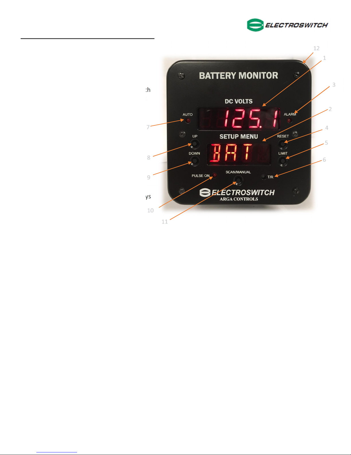
Control Panel Description
1. Main measurement display (upper
readout)
Measurement display: Battery voltage,
+bus voltage, -bus voltage, ground fault
voltage, ripple voltage, ripple current (with
optional sensor), time delay and AC input
mode (single or 3 phase)
2. Parameter/Setup Menu display
(lower readout)
Indicates parameters displayed in the
upper readout and fault indications
3. Alarm LED
Indication for all alarm conditions
4. Reset button
When in latch mode, resets all alarm relays
and alarm indications
5. Limit button
Used to navigate setup menu
6. T/R bi-color LED (Green/Red)
Indicates transmit or receive operation, Red-Transmitting / Green-Receiving
7. Auto LED
Indicates Auto-Scanning (scrolling) mode
8. Up button
Increases limit set point and calibration values (press and hold to increase rate)
9. Down button
Decreases limit set point and calibration values (press and hold to increase rate)
10. Pulse on LED
Indicates internal pulse generator is activated
11. Scan/Manual Button
Toggle between Auto and Manual mode then scrolls through all the readings and set points
12. Buzzer
Located behind the bezel
25-1000-UM 6
 Loading...