

2.75
Ø0.32
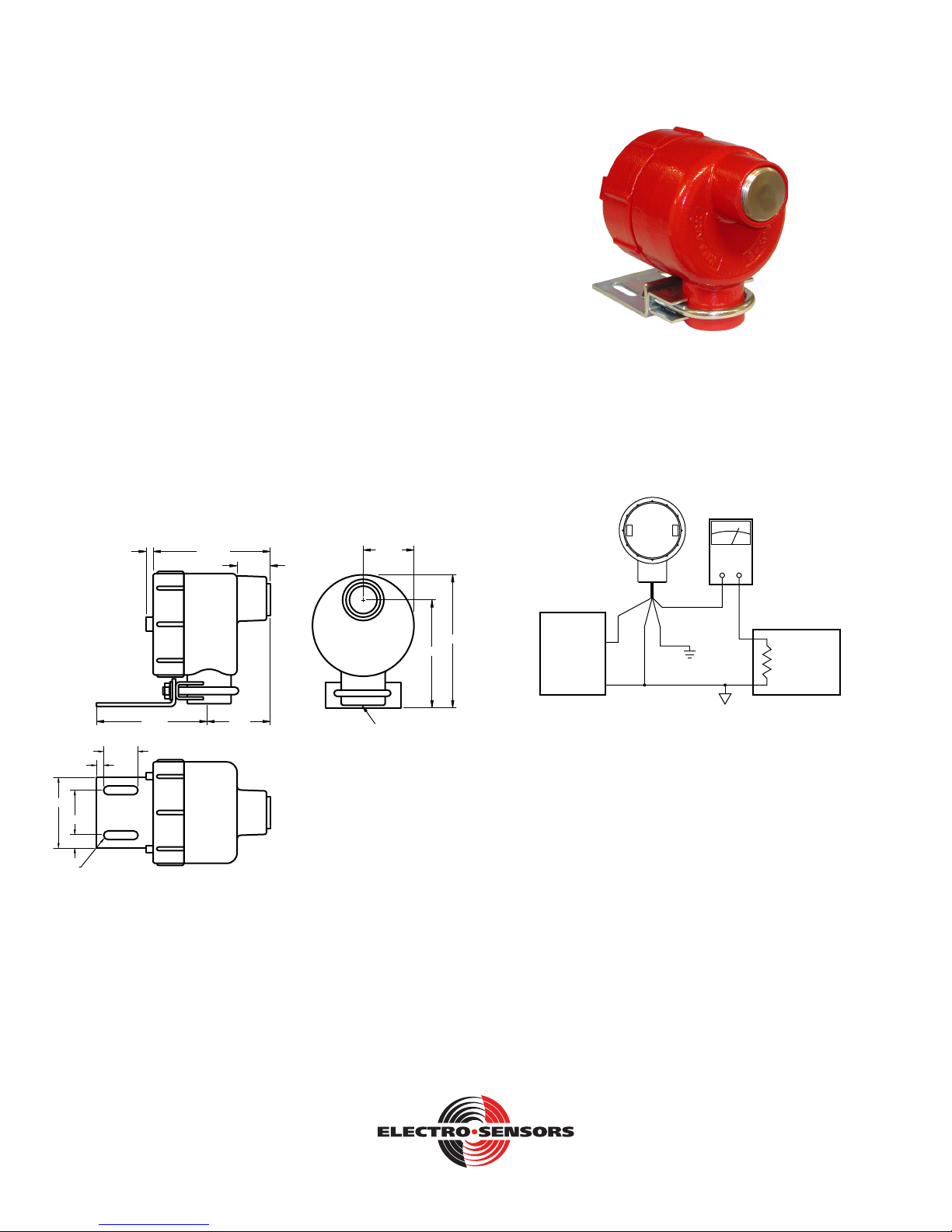
FB420 Shaft Speed Sensor
Description:
Electro-Sensor’s FB420 is a shaft speed sensor that provides a
4-20 mA signal that is directly proportional to the rotational
speed of a monitored shaft.
Since both the 4 mA and 20 mA calibration points are
programmable the user can also if desired operate the FB420 with
the 4 mA offset from 0 RPM.
The FB420 has a 4 digit LCD display that is used for calibration
and for trouble-shooting. The LCD is capable of displaying from
‘0.000’ to ‘9999.’ RPM, or from ‘04.00’ to ‘20.00’ mA.
The FB420 has one relay that can be programmed for either
failsafe over/underspeed alarm.
FB420 Installation:
The FB420 needs a rotating target installed on the application’s
drive-shaft, etc. A typical rotating target is a 255 Pulser Disc (with
or without an optional EZ-Mount bracket), or an optional custommade Pulser Wrap. (See Figure’s 4a, 4b, and 4c).
Figure 2: FB420 Front-View
Electrical connections
The FB420’s electrical connections are as follows:
FB420
0.25 4.40
1.25
0.26
1.63
0.56
4.00
1.38
2.38
1.84
1“ NPT
Figure 1: FB420 Dimensions w/Bracket and U-Clamp
3.90
Ammeter
(optional)
-
TB1-2
+
4-20mA
PLC, Etc.
250 to 500
ohm load
4.81
+24Vdc
Power Supply
(+)
(-)
TB1-1
Shield
TB1-3
Figure 3:
• Connect any shield wire to the earth ground (if used).
• Connect TB1-1 to the power-supply (+24 Vdc) terminal.
• ConnectTB1-2toaresistiveloadof250Ωto500Ω,(usually
this load is internal to a PLC, etc.).
• Connect TB1-3 to the power-supply (-) terminal.
Note: TB1-2 is the 4-20 mA DC output line.
Theothersideofthe250Ωto500Ωloadmustbe
connected to the power-supply (-) terminal.
6111 Blue Circle Drive
Minnetonka, MN 55343
Phone: 952.930.0100
Fax: 952.930.0130
ISO 9001:2000 Certied
Free Catalog and Application Assistance
1.800.328.6170
Visit Us Online
www.electro-sensors.com
990-003400 Revision C
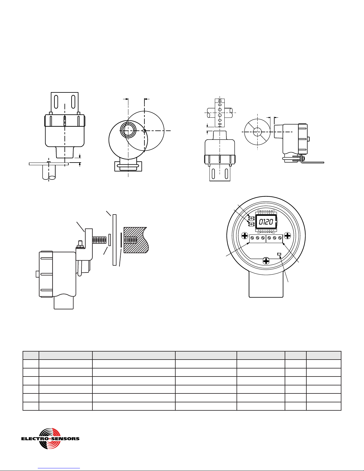
Pulser Disc:
The end of the shaft to be monitored must be center drilled to a
depth of 1/2–inch with a #21 drill and tapped for a 10-32 UNF.
After applying Loctite™ or a similar adhesive on the threads
to keep the pulser disc tight, the pulser disc should be attached,
decal side out with the supplied 10-32UNF machine screw and
lock washer. Dimension (A )is 1/16 inch to 1/4 inch.
The center-line of the magnets (B) must align with the center of
the sensing head as the Pulser Disc rotates.
Pulser Wrap (optional):
Pulserwrapsarecustommanufacturedtottheshafttheywill
be mounted on. When the wrap is shipped, four Allen-head cap
screws hold the two halves of the wrap together. These screws
must be removed so the wrap is in two halves. Place the halves
around the shaft, reinsert the screws and torque them to 8 footpounds. Dimension (A) is 1/16 inch to 1/4 inch.
The center-line of the magnets (B) must align with the center of
the sensing head as the Pulser Wrap rotates.
B
A
Figure 4a: FB420 with 255 Pulser Disc
EZ-Mount Bracket with Pulser Disc (Optional)
Pulser Disc (Included)
EZ-Bracket
Assembly
Spacer
(Included)
FB420
Shaft Center Drilled
and Tapped for
1/2-13 UNC 2A
Retaining
Washer
(Included)
B
A
Figure 4c: FB420 with Pulser Wrap
SW1: Increment Button
SW2: Enter Button
TB1-1: +24Vdc Pwr
TB1-2: 4-20mA Out
TB1-3: DC Ground
SW1
SW2
TB1
A
321
321
TB2
D5
TB2-1: N.O.
TB2-2: Common
TB2-3: N.C.
Relay LED
Figure 4b: FB420 with EZ-Mount Bracket
List of Variables
VA R Mnemonic Description Range Decimal Place Default User’s Value
01 Pulses Per Rev Pulses per revolution of target 0001. to 9999. Fixed at XXXX. 0008
02 Min. RPM RPM value corresponding to 4 mA 0000 to “97.5% of Var03” dec pt tied to Var03 0000
03 Max. RPM RPM value corresponding to 20mA 0.000 to 9999. User selectable 200
04 Relay Function Select Unused, Over-speed, Under-speed 0000. to 0002. Fixed at XXXX. 0000
05 Relay Set-point RPM Relay alarm trip point in RPM 0000 to 9999 dec pt tied to Var03 0000
06 Relay Set-point Delay Alarm event ‘wait’ time in seconds 0000. to 0030. Fixed at XXXX. 0000
Figure 5: FB420 Rear-View (Cover Removed). Showing the
power/signal terminal TB1, the relay terminal TB2, the push-
buttons SW1 and SW2, and the relay LED
Free Catalog and Application Assistance
1.800.328.6170
Website: www.electro-sensors.com
2-4
990-003400 Revision C

The FB420 has two modes of operation:
Normal Mode:
This mode indicates the target’s speed via the 4-20 mA output
signal. The LCD display shows the shaft speed in RPMs, or as a
mA value (04.00 to 20.00 mA). The relay energizes or
de-energizes as per the RPM set-point value.
‘Normal Mode’ is indicated by the absence of the “VAR” icon in
the lower left corner of the display.
Toggling the view in Normal Mode:
Press the SW1 button to toggle the LCD between displaying
the speed value in ‘RPM’ or in ‘mA’.
· When displaying ‘RPM’ values the LCD
does not show the “RATE” icon in the lower right
corner of the display.
· When displaying ‘mA’ values the LCD does show the
“RATE” icon in the lower right corner.
Program Mode:
This mode allows the user to change the variables. The LCD
display shows the present active variable or its value. ‘Program
Mode’ is indicated by the presence of the “VAR” icon in the
lower left corner of the display. Programming is accomplished
by utilizing the two pushbuttons: the Increment button (SW1),
and the Enter button (SW2).
(See Figure 5 showing location of SW1 and SW2).
To enter the Program Mode:
- Press the enter button (SW2). The “VAR” icon will display
and the 4 digits will show “Pr01”.
- Press the Increment button (SW1) repeatedly until you get to
the variable you want to change.
Note: There are 6 user variables, Pr01 through Pr06.
- Press the Enter button (SW2) to access that variable.
- While in that variable you must use the Increment button
(SW1)tochangetheactivedigit(ashingdigit),thenthe
Enter button (SW2) to save and work your way through all the
digits and the decimal place.
- When you are done with that variable you will see “Pr0X, the
‘X’ being the variable you just programmed.
- To step to the next variable use the Increment button (SW1).
To exit the program mode repeatedly press the Increment
button (SW1) until the “VAR” icon disappears. The FB420 is
now back in the normal mode.
Resetting the FB420’s variables to factory-defaults:
- Remove the +24 VDC power.
- Simultaneously press and hold the SW1 and SW2 buttons.
- Apply the +24 VDC power.
- When the LCD shows “rESE”, release the buttons.
- The user variables are then automatically reset to the factorydefault values.
LCD
Display
Messages
Err0
Err1
Err2
Err3
Err4
Flashing
“9999”
Flashing
“04.00”
Flashing
“20.00”
“St0P”
· meanings,
· effects,
· how to clear them if necessary (troubleshooting)
· Var02_MIN_RPM is greater than 97.5% of
Var03_MAX_RPM.
· The output signal is 12 mA, and the relay is in the
de-energized ‘alarm’ state until Err0 is cleared.
· Verify Var02_MIN_RPM and Var03_MAX_RPM,
and modify if needed.
· The FB420’s programmed MaxHz is above the
maximum allowed 9999 Hz: (MaxHz > 9999).
MaxHz = Var01_PPR * Var03_MAX_RPM / 60.
· The output signal is 12 mA, and the relay is in the
de-energized ‘alarm’ state until Err1 is cleared.
· Verify Var01_PPR and Var03_MAX_RPM, and
modify if needed.
· The FB420’s programmed MaxHz is below the
minimum allowed 0.5 Hz: (MaxHz < 0.5).
· The output signal is 12 mA, and the relay is in the
de-energized ‘alarm’ state until Err2 is cleared.
· Verify Var01_PPR and Var03_MAX_RPM, and
modify if needed.
· The system is running at a speed above the
FB420’s absolute maximum rating of 9999 Hz
(i.e., above 9999 Hz + a safety margin).
· The output signal is 20 mA during an Err3.
· Verify Var01_PPR and Var03_MAX_RPM, and
modify if needed.
Or reduce the speed.
Or use a rotating target with a lower PPR.
· The system is running at a speed above the
FB420’s internal range as set by the MaxHz value.
(Note: The FB420 automatically chooses
the best range in which to operate, as per the
MaxHz value. The ranges are: 0 to 9.999 Hz,
0 to 99.99 Hz, 0 to 999.9 Hz, or 0 to 9999 Hz).
· The output signal is 20 mA during an Err4.
· Verify Var01_PPR and Var03_MAX_RPM, and
modify if needed.
Or reduce the speed.
Or use a rotating target with a lower PPR.
· The FB420 is displaying the speed in ‘RPM’, but
the speed is above the LCD’s ‘9999’ capability.
· The output signal is 20 mA during this warning.
· The FB420 is displaying the speed in ‘mA’, but the
speed is below the Var02_MIN_RPM.
· The output signal is 4 mA during this warning.
· The FB420 is displaying the speed in ‘mA’, but the
speed is above the Var03_MAX_RPM.
· The output signal is 20 mA during this warning.
· The monitored shaft is stopped.
· Or, the FB420 is gapped too far from the Disc or
the Wrap.
· Or, the Disc or Wrap is damaged.
· Or, the FB420 is damaged.
· The output signal is 4 mA during this message.
3-4
Free Catalog and Application Assistance
1.800.328.6170
Website: www.electro-sensors.com
990-003400 Revision C

FB420 General Specications:
Input Power Input Current Fuse Type
REQUIRES
ISOLATED
+24 VDC ±10%
Input Signal Parameters
Type Magnetic alternating
Range of Operation
Gap distance 1/16” to 1/4”
Analog Output
Signal
Type
Accuracy ±0.7%
4-20 mA
Resolution
Required
impedance
Max signal distance
Relay Output Data Parameters
Number Available 1 SPDT Form C
Relay Contact Rating
Relay Functions
Physical/Enviroment Parameters
55mA (when 20mA
signal and relay
energized)
Overall = 0.1 Hz to 9999 Hz.
(With 8 PPR = 0.75 RPM to 9999* RPM.
*Note: the LCD can only display up to 9999).
Parameters
4-20 mA, with programmable end-points:
(4 mA @ user’s Min RPM)
(20 mA @ user’s Max RPM)
Depends on calibration, but can be a best of
0.001 mA per increment
4-20mAoutputneedsa250to500Ωload
Using a 3-conductor cable with
17.5Ω/1000ft.perconductor,themaximum
length of cable usable with the FB420 is:
· 3800 ft. when not using the relay
· 2300 ft. when using the relay
5 Amp @ 30 Vdc
5 Amp @ 250 Vac
Fail-safe ‘alarm’ state is relay de-energized:
· Unused,
· Fail-safe Over-speed,
· Fail-safe Under-speed,
REQUIRES
External Fuse 0.100A
slo-blo
Class I, Div 1, Group C, D
Class II Groups E, F, G
UL File: E249019
Additional Rating NEMA 4X, Gasket Provided
Operating Temp -40ºC to +65ºC (-40ºF to +149ºF)
Storage Temperature -40ºC to +80ºC (-40ºF to +176ºF)
Humidity 0% to 90% non-condensing
Denitions:
Pulse Per Rev (Var01)
The Pulse Per Rev value, or PPR, is the number of pulses generated
per revolution of the magnetic target mounted on the rotating shaft.
Note: See LCD messages “Err1” through “Err4” regarding Var01.
MIN RPM value (Var02)
The MIN_RPM value sets the speed corresponding to an output of
4 mA. The MIN_RPM value can be anywhere from 0000** RPM up
to 097.5% of Var03 MAX_RPM, with the decimal point locked in
the same position as Var03.
**Note: If Var02 = 0000 RPM, then the corresponding 4 mA speed is
either 0.1 Hz or 0.5 Hz, as per the ‘MaxHz’ value.
Note: See LCD message “Err0” regarding Var02.
MAX RPM value (Var03)
The MAX_RPM value sets the speed corresponding to 20 mA output.
Note: See LCD messages “Err0” through “Err4” regarding Var03.
Relay Function Selection (Var04)
The Relay Function Selection value determines how the relay responds.
The choices are:
· Unused (0000),
· Fail-safe Over-speed (0001),
· Fail-safe Under-speed (0002).
Relay RPM Set-point value (Var05)
The Relay RPM Set-point value programs the trip point for the relay.
The relay drops when the RPM set-point value is passed (i.e., goes into
the de-energized ‘alarm’ state, with the green relay LED = OFF).
Note: There is however a 6.25% hysterisis for pulling-in the relay
(i.e., returning to the energized ‘non-alarm’ state, with the green relay
LED = ON).
· For under-speed operation it means the shaft speed must be 6.25%
faster than the set-point to pull-in.
· For over-speed it means the shaft speed must be 6.25% slower than
the set-point to pull-in.
Note: See Figure 5 showing the location of the green relay LED.
Relay Set Point Delay (Var06)
The Relay Set Point Delay determines how many seconds an ‘alarm’
event condition must exist before de-energizing the relay.
Loss of feedback
If feedback pulses are lost when running, the FB420 waits an amount of
time equal to “(1/real-time-frequency) + another 12.5% of that” before it
begins to cascade the 4-20 mA output down towards 4 mA, and the LCD
down towards “St0P”.
Software identication
Duringpower-uptheLCDrstshows“8.8.8.8.” along with the icons
“VAR” and “RATE” (as a test). Next, the LCD shows the software ID in
the “X.X.X.X.”format,wherethersttwodigitsaretheversionnumber,
and the last two digits are the revision number.
Resolution (of the 4-20 mA signal, and LCD’s RPM value)
The 4-20 mA signal: For best resolution of the 4-20 mA output, the
FB420 automatically selects from one of four internal operating ranges
as per the programmed ‘MaxHz’ value. The ranges are:
· If ‘MaxHz’ is between 0.5 Hz and 9.999 Hz,
then the internal operating range = 0.1 Hz to 9.999 Hz.
· If ‘MaxHz’ is between 0.5 Hz and 99.99 Hz,
then the internal operating range = 0.1 Hz to 99.99 Hz.
· If ‘MaxHz’ is between 0.5 Hz and 999.9 Hz,
then the internal operating range = 0.5 Hz to 999.9 Hz.
· If ‘MaxHz’ is between 0.5 Hz and 9999. Hz,
then the internal operating range = 0.5 Hz to 9999. Hz.
This allows the FB420 to use the smallest frequency range to cover
the application, thus improving resolution. Then depending on the
programmed MIN_RPM and MAX_RPM values, the resulting 4-20 mA
resolution can be as tight as 0.001 mA per increment.
The LCD’s RPM value: The Var03_MAX_RPM’s decimal point
position affects the resolution of the LCD displayed RPM value.
For best resolution of the displayed RPM value, program Var03 with the
greatest number of decimal places possible (XXXX. to X.XXX).
Note: Var03 decpt position has no effect on the 4-20 mA resolution.
Note: Specications subject to change without notice.
Copyright © 2009, Electro-Sensors, Inc.
Free Catalog and Application Assistance
1.800.328.6170
Website: www.electro-sensors.com
4-4
990-003400 Revision C
 Loading...