

Electron
Microscopy
Sciences
INSTRUCTIONAL MANUAL
CAT. #72907-01
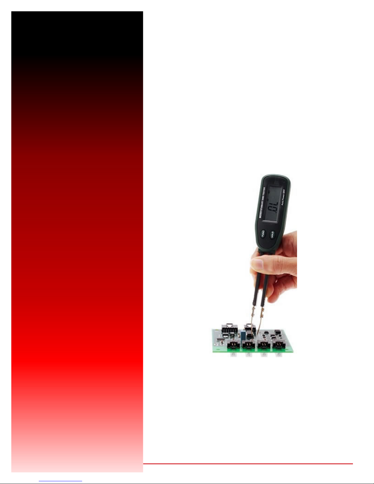
Smart Tweezers – StraightTips
www.emsdiasum.com
sgkcck@aol.com
P.O. Box 550, 1560 Industry Road, Hateld, PA 19440
Electron Microscopy Sciences
Toll Free: 1-800-523-5874
Tel: 215-412-8400 s Fax: 215-412-8450
Introduction
Carefully read and understand this manual before using the Tester.
Precise, non-magnetic tips reliably contact smallest SMD (surface mount device). The Quick Test tweezers gives users an
easy way to sort and evaluate loose components and to perform on-board measurements and debugging. Surface mount
devices are usually tiny and without wire leads, making it much more difcult to test and identify SMD than conventional
components. Precise tips, made of non-magnetic steel, are able to pick and reliably contact even the smallest SMD components, or take measurements from the device already mounted on a board. The probe can also be used to test conventional
components with wire leads too short to insert into the test terminals.
Features:
• Measures AC/DC voltage, resistance, continuity & diode test
• Auto Scanning Mode/Auto range
• Testing pins gold plated to reduce resistance and prevent rust
• Uses Lithium battery CR2032, included
• Will automatically identify whether component is a resistor, capacitor or diode
Safety Warnings
WARNINGS
• Never use Tester on live circuits.
• DO NOT use a damaged Tester.
• Inspect the Tester case before using
• Inspect the Pin Holder – ensure that the gold-plate is not damaged
• To prevent the pin tip from damage, DO NOT use the Tester as tweezers
• DO NOT apply external voltage between the two pins.
• DO NOT use in an environment with explosive gas, vapor, or dus
• There are situations where hazardous condition may exist, even though the Tester is not
used to measure DC/AC Voltage or current.
Specications
• 3000 count LCD display
• Full automatic measurement: Auto scanning the Resistance/Capacitance/Diode.
• Function selection by one FUNC Push Button
• Data Hold function
• Continuity Checking function
• Over Load Indication (OL)
• Low Battery Indication
• Power Supply: 3V Lithium Battery (CR2032)
• Test Pins are gold-plated
• Auto Power OFF: If the Tester is idle for more than 10 minutes, Tester automatically turns the power off.
• Operating temperature and Humidity: 0 ~ 40oC (32 ~104oF) and < 80% RH
• Storage temperature and Humidity: -10 ~ 50oC (14 ~ 122oF) and <70%RH
• Safety Class: IEC1010-1, CAT II
• EMC: According to CE regulation 89/336
• Dimension (L x W x H): 170 x 31 x 17 mm; Weight: approx. 48.6 g
• Environmental condition: Indoor use only, up to an altitude of 2000 meters
www.emsdiasum.com
sgkcck@aol.com
P.O. Box 550, 1560 Industry Road, Hateld, PA 19440
Electron Microscopy Sciences
Toll Free: 1-800-523-5874
Tel: 215-412-8400 s Fax: 215-412-8450

Tester Diagram
LCD Display
1. LCD
2. “HOLD” Push Button
3. “FUNC” Push Button
4. Pin Holder
5. Gold-plated Test Pin (INPUT Terminal)
6. Gold-plated Test Pin (COM Terminal)
7. Battery cover
Auto Scanning Mode
Auto Ranging
Data Hold
Diode Checking Mode
Continuity Checking Mode
Low Battery
Indicator
Resistance Units
(Ω, KΩ, MΩ)
Capacitance Units
(nF, uF, mF)
Using the Tester
When the 3V lithium battery is installed, the Tester power is ON.
Once powered on, the Tester will perform the Scanning Mode, which will be displayed on the LCD. It will automatically identify the resistor, capacitor, diode and continuity measurement mode.
FUNC Button: Choose the function desired – Resistance, Capacitance, Diode, Continuity.
HOLD Button: Select measurement mode manually by pressing the HOLD button. Use this button to enter or exit the hold
mode In any measurement mode. In the data hold mode, the Tester stops updating LCD, storing current measuring data
and displaying the measured data and holding it until pressing the “HOLD” key once again.
NOTE: After auto power-OFF is active, push any of the buttons to turn on the Tester again.
www.emsdiasum.com
sgkcck@aol.com
Electron Microscopy Sciences
P.O. Box 550, 1560 Industry Road, Hateld, PA 19440
Toll Free: 1-800-523-5874
Tel: 215-412-8400 s Fax: 215-412-8450

Electrical Specications
Function Range Best Resolution Accuracy
Resistance
300Ω / 3KΩ
30KΩ / 300K / 3MΩ
0.1Ω
±(1%rdg+ 2dgt)
30MΩ ±(1.2%rdg+ 3dgt)
Capacitance
Diode Check
3nF / 30nF / 300nF
3uF / 30uF
300uF / 3mF / 30mF
Open Voltage: 2.8V
Testing Current : 2mA
1pF
±(2%rdg+ 3dgt)
±(3%rdg+ 3dgt)
Continuity Check When the resistance is less than 30Ω, the Buzzer is sounded.
Operations
Scanning Mode
When two pins are in touch with the object being measured, the measured value will be displayed on the LCD.
CAUTION: When measuring SMD device on the PCB, you must disconnect power and discharge all high-voltage
capacitors.
Resistance Measurement
Auto scanning Mode & Auto range: 300.0Ω — 3.000MΩ
Selected Resistance measurement Mode with the FUNC key: The range is extended to 30 MΩ, i.e.300.0Ω — 30.00MΩ
When overloaded, the OL symbol will be displayed on the LCD.
Capacitance Measurement
Auto scanning & Auto range: 3.000nF — 300.0uF.
When Capacitance Mode is selected by the FUNC key, the range is extended to 30.00mF, i.e. 3.000nF—30.00mF.
CAUTION: To avoid damage to the Meter or to the equipment under test, disconnect power and discharge all
high-voltage capacitors before measurement capacitance.
Diode Check
Select Diode Mode with the FUNC button.
Use the diode test mode to check diodes, transistors and other semiconductor device. The diode test mode sends a cur-
rent through the semiconductor junction and measures the voltage drop across the junction. A good silicon junction drop is
between 0.5V — 0.8V.
For forward voltage drop reading on any semiconductor component, the test pin, connected to the ‘INPUT’ terminal, is
in touch with the component anode and the another test pin is in touch with on the component cathode. The measured value
is displayed on the LCD.
Reverse the test pin and measure the voltage across the diode again.
– If diode is good, the display shows OL.
– If diode is shorted, the display shows 0 (zero) in both direction.
– If display shows OL in both direction, the diode is open.
Continuity Check
Select the Continuity Mode by FUNC button.
When the resistance reading is less than 30Ω, the buzzer generates 2KHz beep to indicate continuity.
www.emsdiasum.com
sgkcck@aol.com
Electron Microscopy Sciences
P.O. Box 550, 1560 Industry Road, Hateld, PA 19440
Toll Free: 1-800-523-5874
Tel: 215-412-8400 s Fax: 215-412-8450

Maintenance
Replacing The Battery (Battery type: Lithium Battery 3V CR2032)
When the battery symbol is displayed on the LCD, the battery needs replacing.
1. Open the battery cover on the bottom case with a screwdriver.
2. Remove old battery and snap new one into battery holder.
Cleaning
The meter can be cleaned with soft clean cloth to remove any oil, grease or grim.
Do not use any liquid solvent or detergent.
www.emsdiasum.com
sgkcck@aol.com
Electron Microscopy Sciences
P.O. Box 550, 1560 Industry Road, Hateld, PA 19440
Toll Free: 1-800-523-5874
Tel: 215-412-8400 s Fax: 215-412-8450

For any questions or for ordering information,
please contact Customer Service at
1-800-523-5874
Electron
Microscopy
Sciences
Thank you for choosing
Electron Microscopy Sciences!
www.emsdiasum.com
sgkcck@aol.com
Tel: 215-412-8400 s Fax: 215-412-8450
Electron Microscopy Sciences
P.O. Box 550
1560 Industry Road, Hateld, PA 19440
 Loading...