

Electron Microscopy Sciences 72088-01, 72088-02 Instruction Manual
Electron
Microscopy
Sciences
INSTRUCTIONAL MANUAL
CAT. #72088-01, 72088-02
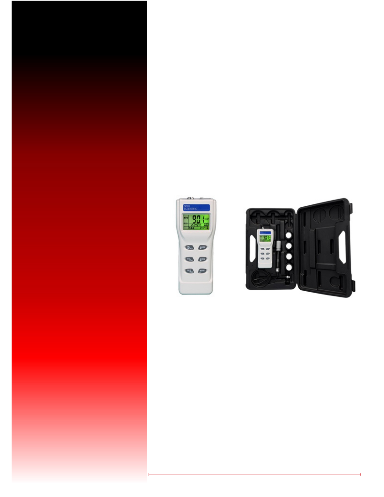
Advanced pH Meter &
Advanced pH Meter Kit
www.emsdiasum.com
sgkcck@aol.com
Electron Microscopy Sciences
P.O. Box 550 s1560 Industry Road s Hateld PA 19440
Toll Free: 1-800-523-5874
Tel: 215-412-8400 s Fax: 215-412-8450
1
Introduction
Benchtop level analysis in the eld! Reads either pH (in 0.01 resolution) or mV in large digits, with time, date, and temperature (in °C or °F) shown simultaneously on the lower display. Also indicates stable reading, low battery and displays
calibration data. Scroll 99 data points with time stamps and min/max readings directly on the backlit LCD.
Features:
• Multi-display LCD screen
• 5 points pH calibration
• N.I.S.T. buffer recognition
• Maximum and minimum
• Hold function
• Backlight for dark environment operation
• Easy to view probe calibration data
• “Ready” icon on LCD display indicates stability for reading
• USB connection for online logging and uploading 99 mem-
ories to PC for analysis
• Automatic or manual temperature compensation
• External power adapter (optional) for long use testing
• Auto power off to save battery
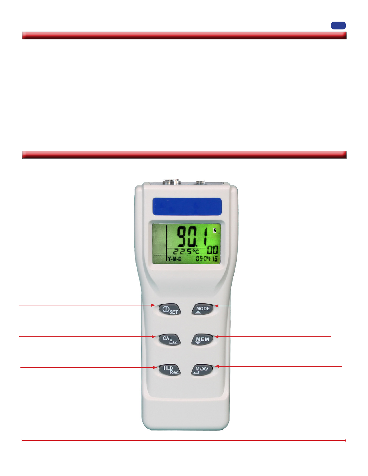
LCD Display
• HLD Holds the current reading on the dis-
play.
• ATC means the meter is in automatic temperature compensation mode.
• MAX, MIN indicate maximum or minimum
memory value.
• READY indicates the reading is stable.
• CAL indicates the meter is in calibration
mode.
• REC indicates the meter is in recall mode.
Press to turn meter on/off. Press and hold
for more than 1 second to enter SET mode.
Switch between NORMAL and CALIBRA-
TION mode Press to enter manual tem-
perature setting. In calibration, setting or
recall mode, press to return to normal.
Press to freeze reading. Press again to re-
lease. Press for more than 1 second to switch
between NORMAL and RECALL mode.
{
HLD
ATC
MAX
MIN
READY
CAL
REC
%
mV
pH
• LCD display indicates pH, mV, ORP
(mV).
• pH, mV indicates the unit of measure
displayed.
• The two digits to the right of °C °F on
the display indicate the total number
{
of records that contain stored data.
• Real time 88:88:88 is real-time Y-M-D
or H:M:S.
• °C/°F are temperature units of measure.
Press to switch mode.
Press to increase setting value.
Press to save current reading.
Press to decrease the setting value.
Press to conrm calibration/parameter
setting. Press to view the min/max of the
memory in recall mode.
www.emsdiasum.com
sgkcck@aol.com
P.O. Box 550 s 1560 Industry Road s Hateld PA 19440
Toll Free: 1-800-523-5874Electron Microscopy Sciences
Tel: 215-412-8400 s Fax: 215-412-8450

Setup Mode
The advanced Setup Mode allows you to customize the following meter preferences and defaults:
2
P 1.0 Memory Transmission
P 2.0 Clear Memory
P 3.0 Electrode (pH probe)
P 4.0 Buffer Solution (pH)
P 5.0 Ready Function
P 6.0 Temperature Units
P 7.0 Real Time Clock
P 8.0 Reset
P 1.0 Memory Transmission – transfers stored data from the meter to the computer
NOTES: R To enter Setup Mode, press SET for about 2-3 seconds while the meter is in Normal Mode.
R To exit Setup Mode without saving, press ESC until the Normal Mode appears.
R If the meter is in Setup Mode, press ESC twice to exit.
1. Connect USB cable to the right side of the meter and connect the other end of the cable
with the D-sub connector to the computer’s serial port. Run the software associated with
this feature.
2. Press SET for 2 seconds to enter setup.
3. The “TR” icon appears on the middle of the LCD display and P1.0 displays under the “TR” icon.
4. Press MN/MX/AV. The “OUT” icon ashes on the upper display and P1.1 displays under
the “OUT” icon. This indicates that the memories are transferring. After transmission, the
LCD will return to P1.0.
NOTE: The meter can store up to 99 records for each parameter. To transmit data for a different parameter, press ▲ to select desired parameter before entering setup.
P 2.0 Clear Memory
The memory clear program is designed to clear 99 memories at one
time. Proceed cautiously, as this operation cannot be reversed.
Press MODE to select the parameter you want cleared before entering Setup Mode.
1. Press SET for 2 seconds to enter setup.
2. Press ▲ to select memory clear function.
3. The “CLR” icon appears on the middle display and P2.0 illuminates in the lower display.
4. Press MN/MX/AV to enter P2.1.
5. The default “NO” icon ashes on the middle display and P2.1 appears in the lower dis-
play.
6. Press ▲ to change the status from “NO” to “YES” and then press MN/MX/AV again to
conrm clearing of all memory. The LCD display will return to P2.0 when memories are
deleted.
www.emsdiasum.com
sgkcck@aol.com
P.O. Box 550 s 1560 Industry Road s Hateld PA 19440
Toll Free: 1-800-523-5874Electron Microscopy Sciences
Tel: 215-412-8400 s Fax: 215-412-8450

Setup Mode, continued
P3.0 View Slope & Offset
Press MODE to select the parameter you want cleared before entering Setup Mode.
1. Press MODE to select probe type as pH.
2. Press SET for 2 seconds to enter setup.
3. Press ▲ until the icon “ELE” appears in the middle display and
P3.0 appears in the lower display.
4. Press MN/MX/AV to enter P3.1, the LCD displays one of four
available slope values; P3.1, P3.2, P3.3, P3.4. If the value is less
than 75% or more than 115%, change the probe immediately.
5. Press MN/MX/AV to enter P3.2, P3.3, and P3.4.
NOTE: The solution range denition differs between NIST and Cus-
tom buffers.
Solution Range
Buffer P3.1 P3.2 P3.3 P3.4
NIST 0.00 ~ 4.01 4.01~ 6.86 6.86~9.18 9.18~14.00
3
Custom 0.00 ~ 4.50 4.50~7.00 7.00~9.50 9.50~14.00
6. Press MN/MX/AV to enter P3.5 and view the offset value. The offset value is the mV value of pH 7 and the default
offset value is 0.0. The offset value will be different after calibration. If the value is outside the range of ± 60 mV,
replace the probe.
P4.0 pH Calibration Buffer
This meter allows the selection of two different types of pH buffers: NIST or CUSTOM. Selection of the proper buffer type
more accurately calibrates the probe to specic requirements.
NIST buffer has ve settings:
R
pH 1.68, 4.01, 6.86, 9.18, 12.45
CUSTOM buffer has ve ranges:
R
pH 1.00-3.00, 3.50-5.50, 6.00-8.00, 8.50-10.50, 11.50-13.50
Select Buffer
1. Press SET for 2 seconds to enter setup.
2. Press ▲ to select pH buffer. “BUF” will appear on the middle of the LCD and P4.0 will
appear on the lower portion.
3. Press MN/MX/AV to enter P4.1. The default “NIS” (NIST) will ash on the LCD and P4.1
will appear on the lower portion of the display. If you use N.I.S.T. buffers, press MN/MX/
AV to conrm and the meter returns to P4.0.
4. If your requirement is not for NIST buffers, press ▲ to change the status to CUSTOM
buffer.
5. Press MN/MX/AV to conrm and the meter will return to P4.0.
www.emsdiasum.com
sgkcck@aol.com
P.O. Box 550 s 1560 Industry Road s Hateld PA 19440
Toll Free: 1-800-523-5874Electron Microscopy Sciences
Tel: 215-412-8400 s Fax: 215-412-8450
Setup Mode, continued
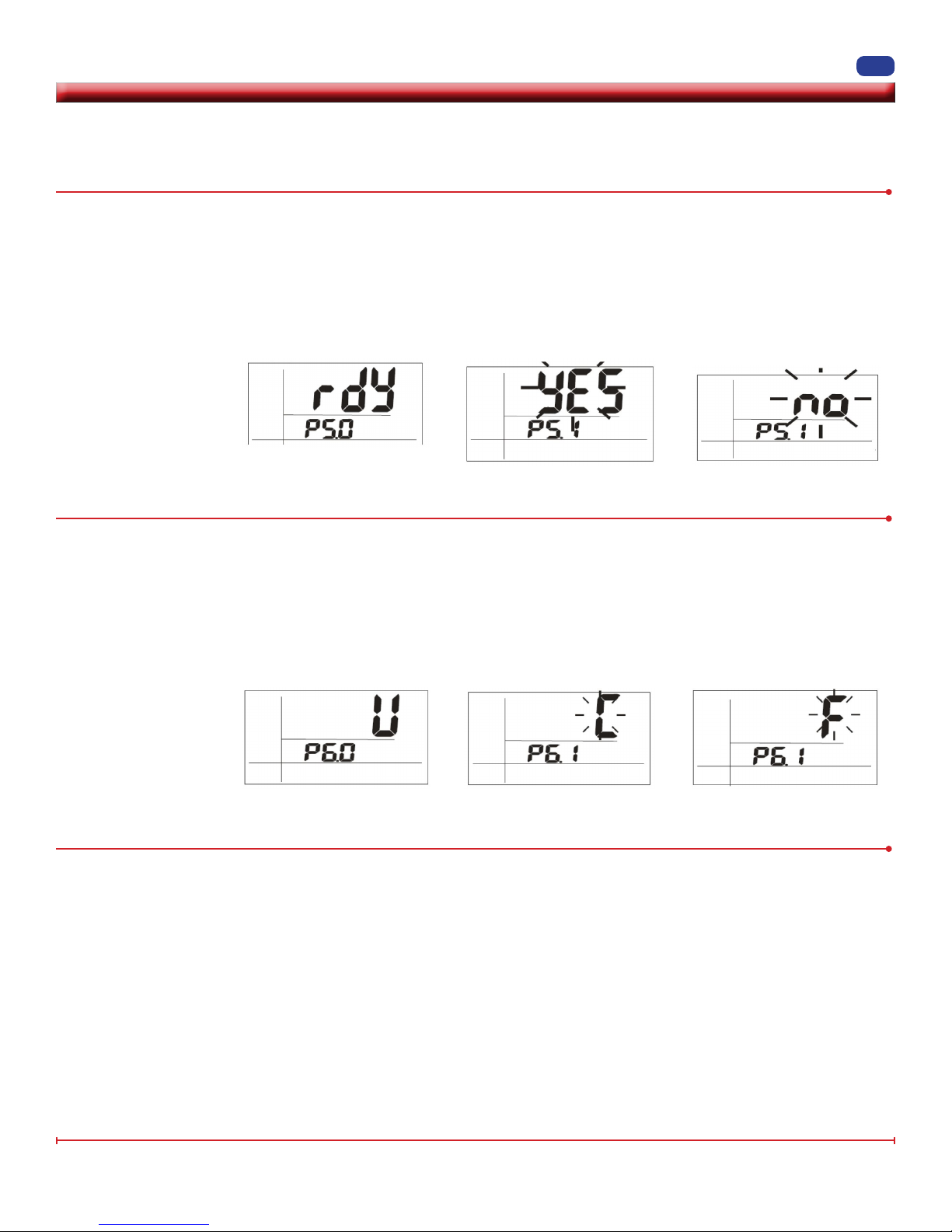
P5.0 Ready Icon – enables/disables the “READY” icon, indicating that the measured reading is stable.
1. Press SET for 2 seconds to enter setup.
2. Press ▲ to select “READY” on the display.
3. Press MN/MX/AV to enter P5.1. “YES” will ash on the LCD display and P5.1 will appear on the lower display.
4. Press ▲ to switch between YES or NO.
5. Press MN/MX/AV to conrm.
6. Press ESC to return to Normal Mode.
P6.0 Temperature Units – select either Celsius or Fahrenheit temperature scale
4
1. Press SET for 2 seconds to enter setup.
2. Press ▲ to select “U” on the upper display. P6.0 is displayed in the lower portion of display.
3. Press MN/MX/AV to enter P6.1. The last selected unit “C” or “F” will appear on the LCD.
4. Press ▲ to select either display.
5. Press MN/MX/AV to save the selection.
6. Press ESC to return to Normal Mode.
P7.0 Real Time Clock Setting – adjusts the meter’s internal clock
NOTE: An internal battery powers the real time clock independent of the power source running the meter.
1. Press SET for 2 seconds to enter setup.
2. Press ▲ to select “RTC” on the LCD display. P7.0 appears on the bottom of the display.
3. Press MN/MX/AV to enter P7.1. The year ashes in the lower right corner of the LCD display. (The year is the last two
digits only; for example, 1999 would be 99).
Symbol: Y-M-D H:M:S
Denition: Yr.-Mo.-Day Hr.-Min.-Sec.
Range: 99-12-31 23-59-59
4. Press MN/MX/AV to step through the following “P’s.” All are two digits.
P7.1 = Year P7.2 = Month P7.3 = Day
P7.4 = Hour P7.5 = Minute P7.6 = Seconds
5. Press ▲ and ▼ to adjust values up or down, respectively.
6. Press ESC to return to P7.0 and Normal Mode.
www.emsdiasum.com
sgkcck@aol.com
P.O. Box 550 s 1560 Industry Road s Hateld PA 19440
Toll Free: 1-800-523-5874Electron Microscopy Sciences
Tel: 215-412-8400 s Fax: 215-412-8450
 Loading...