

Electronika LDMOS UHF SERIES User Manual
91
LDMOS UHF SERIES
MEDIUM POWER TV AMPLIFIER
User’s manual

92
This page is intentionally blank
93
Section 1 - Information
Contents:
1.1 Description
1.2 Main Features
1.3 Technical characteristics
1.4 Front panel
1.5 Rear panel
Rear connections

94
1.1 DESCRIPTION
The amplifier belongs to the Medium Power Amplifier products family of T elevision Amplifiers fully in solid
state LDMOS technology .
These TV Amplifiers operate in the UHF Band with Common amplification process (separate amplification
available) of the V ideo and Audio carriers. This Amplifier family has been designed to of fer to the customer
high performances, high reliability and greater simplicity in its operation and maintenance procedures.
The V ideo and Audio signal processing is provided for all TV Standards and all types of Audio applications
(Mono & Dual Sound - NICAM) together with the different colour systems such as P AL - NTSC - SECAM.
Thanks to the amplitude and phase and non linearity pre-correction circuit, it is possible to cancel the distortions
in the output stage, thus cutting down the operating costs.
Due to the common amplification design, the transmitter is easily upgradeable to any digital TV standard:
DVB-T , DVB-H, DMB-T , ATSC. It is only necessary to replace the modulator and the RF output band pass
filter, all the other components are used without any change.
The cooling system is fully contained into the amplifier, and it is based on forced air flow . A powerful and very
low acoustic noise blower is used. A front panel air dust filter is available, sized in order to enable easy
replacement.
The user interface is based on a graphics display , where all the parameters are showed. A detailed log of
events and alarm help the maintenance of the system.
The unit can be fully controlled in REMOTE mode via PC direct-link or via PSTN, GSM or Ethernet networks
by means of Elettronika Remote Control System.
The system can be easily upgraded with dual drive option.
Besides, the transmitter can be easily integrated in a 1+1 or more complex N+1 redundancy configurations.
1.2 MAIN FEA TURES
- LDMOS T echnology;
- Forced-air cooling system;
- Analog and Digital input signal;
- High efficiency;
- Wir ed and serial r emote control (RS232 or RS485);
- All voltages and currents available on display;
- Output filter included.
MEDIUM POWER TV AMPLIFIER
SERIES

95
1.3 TECHNICAL CHARACTERISTICS
RF SECTION
- Analog Operation
Frequency Range ........................................................................................................................................................... UHF
Output Power (±0.5dB) ............................................................................................................................................... 1300W
Amplification Class .......................................................................................................................................................... AB
Gain (±2dB) ....................................................................................................................................................................28dB
Technology.............................................................................................................................................Solid State LDMOS
RF Input Connector ................................................................................................................................................ N Female
Impedance.......................................................................................................................................................................50Ω
RF Output Connector (Amplifier / Rack) ........................................................................................... 7/16” Female / EIA 7/8”
Impedance.......................................................................................................................................................................50Ω
- Digital Operation
Frequency Range ........................................................................................................................................................... UHF
Digital Output Power (DVB-T) ............................................................................................................................. 300W RMS
Digital Output Power (ATSC)...............................................................................................................................500W RMS
DVB-T Modes......................................................................................................... All the modes listed in ETSI EN 300 744
DVB-T MER .......................................................................................................................................................> 33dB RMS
DVB-T Shoulders Attenuation (After non-critical mask cavity filter) ................................................................> 40dB RMS
DVB-T Output Spectrum .............................................................................................................Compliant ETSI EN 300 744
A TSC Symbol Rate ...................................................................................... 10.76MBaud/s (Compliant to A TSC Doc. A/53)
A T SC SN R .........................................................................................................................................................> 27dB RMS
A TSC Shoulders Attenuation (After simple mask cavity filter ref. total output power) .....................................> 46dB RMS
A TSC Output Spectrum ......................................................................................................... Compliant to A TSC Doc. A/64
REMOTE CONTROL SECTION
Parallel Interface...........................................................................................................................ON/OFF , Alarms, Interlock
Serial Interface ............................................................................................................................. RS232 or RS485 Selectable
METERING
Output Forward Power (Peak or RMS)
Output Reflected Power (Peak or RMS)
Unbalance Power
Heat sink T emperature
Input Power (Peak or RMS)
RF Modules Current
Power Supply Voltage
W orking Timer
INDICATIONS
Cooling Blower W orking (W ith icon on front display)
Transmitter Interlock (W ith icon on front display)
Alarm (With red LED on front panel)
Transmitter ON/OFF (W ith green LED on front panel)
Remote ON/OFF (With orange LED on front panel)

96
PROTECTIONS
Output Forward Power
Output Reflected Power
Unbalance Power
RF Modules Current
Power Supply Voltage
PROTECTIONS
Forward Power (Analogue) .........................................................................................................................................1500W
Reflected Power (Analogue) .........................................................................................................................................150W
Forward Power (DVB-T)................................................................................................................................................400W
Reflected Power (DVB-T) ............................................................................................................................................... 40W
Forward Power (A TSC) .................................................................................................................................................600W
Reflected Power (A TSC) ................................................................................................................................................ 60W
Unbalance (Analogue)..................................................................................................................................................300W
Unbalance (DVB-T).......................................................................................................................................................100W
Unbalance (A TSC) ........................................................................................................................................................150W
Temperature ................................................................................................................................................................... 75°C
I
DC
.......................................................................................................................................................................................................................................................................................................................
18A
V
DC
.......................................................................................................................................................................................................................................................................
Min 10V - Max 33.5V
GENERAL
Power Supply Voltage ............................................................................................................................................. 90 - 260V
Power Supply Frequency ........................................................................................................................................ 50 - 60Hz
Power Factor .................................................................................................................................................................> 0.98
Analog Power Consumption (Black) ......................................................................................................................... 3.45kV A
Digital Power Consumption (DVB-T) .......................................................................................................................... 2.2kVA
Digital Power Consumption (ATSC) ...........................................................................................................................2.5kVA
Housing (Amplifier / Rack) ...................................................................................................................................... 6U / 20U
W eight (Amplifier / Rack)................................................................................................................................... 63kg / 175kg
Airflow ............................................................................................................................................From 330m3/h to 500m3/h
Temperature ..................................................................................................................................................... -5°C to +45°C
Options
- Non critical mask, DVB-T , Output filter
- Critical mask, DVB-T , Output filter
- Stringent emission mask, ATSC, Output filter
1
AUTV/500LD, 2AUTV/1000LD, 3AUTV/1500LD
97
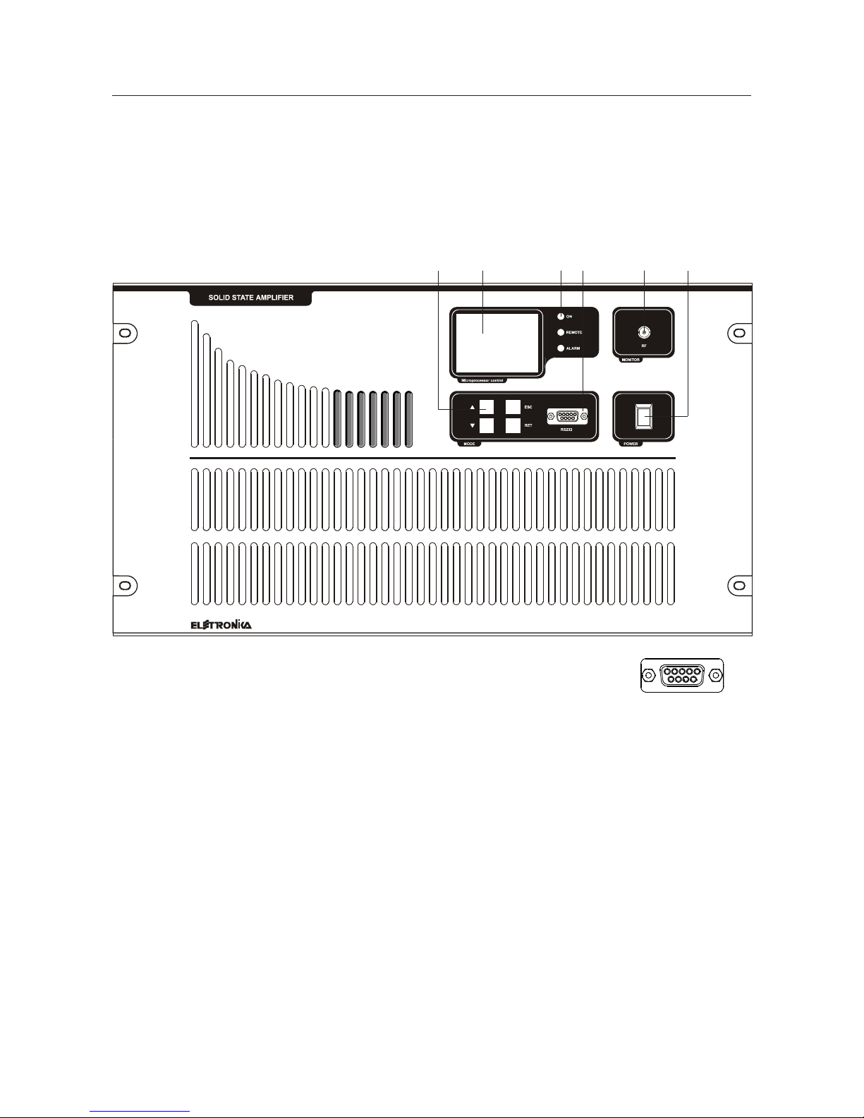
1.4 FRONT P ANEL
2 3 51
1. Function keys
2. LCD Graphic Display
3. Status LEDs
4. RS232 Socket
5. RF Monitor Connector
6. Main Switch
64
RS232 for connection
to PC with ERCoS software
and for firmware upgrade
Pin 2: TX
Pin 3: RX
Pin 5: GN D
98
FUSE
FUSE
FUSE
1
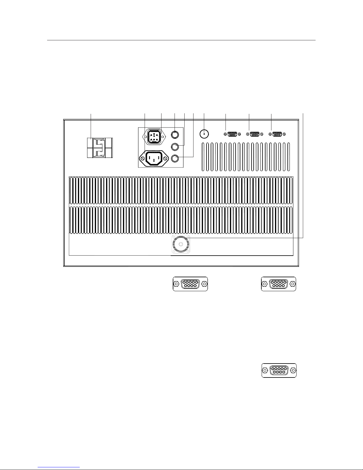
1.6 REAR P ANEL
1. Breaker
2. AC 220V OUT Socket
3. AC 400V IN Socket
41. F AN 3.15A Fuse
42. CONTROL BOARD 1A Fuse
43. EXCITER 4/8A Fuse
5. RF IN Connector
6. RS485 Socket
7. EXCITER Socket
8. TELEMEASURES Socket
9. RF OUT Connector
62
3
5 97 8
Wired Telemeasures connector
Pin 1: FWD power (Analog out)
Pin 2: REF power (Analog out)
Pin 3: T emperature (Digital out)
Pin 4: Interlock (Digital in)
Pin 5: GN D
Pin 6-7:Free contact (Digital out)
Closed when Alarm
Pin 8: 0V=ON / 5V=Normal (Digital in)
Pin 9: 0V=OFF / 5V=Normal (Digital in)
EXCITER for connection
to Driver Module
Pin 1: GN D
Pin 2: 0V=Normal / 5V=AGC Alarm
(Digital out)
Pin 3: 0V=Normal / 5V=AGC Alarm
(Digital out)
Pin 8: FWD power (Analog out)
Pin 9: REF power (Analog out)
RS485 for connection
to RCU or Amplifier Control
Pin 2: RX- Pin 5: GN D
Pin 3: RX+ Pin 7: TXPin 4: +5V Pin 8: TX+
4
2
4
3
4
1
99
Section 2 - Installation
Contents:
2.1 Operating environment
2.2 First installation
2.3 Connection with VEGA Transmitter
2.4 Stand-alone Amplifier configuration in Dual Drive version
2.5 Slave multi-Amplifier configuration with Amplifier Control
2.6 Stand-alone Amplifier configuration with Elettronika RCU
2.7 Stand-alone Amplifier configuration with direct PC connection

100
2.1 OPERA TING ENVIRONMENT
Y ou can install the equipment in a standard component rack or on a suitable surface such as a bench or desk.
In any case, the area should be as clean and well-ventilated as possible. Do not locate the equipment directly
above a hot piece of device. The upper lid can be dismounted to allow an easy internal access. The equipment
is designed with a modular design, that is each circuit is realized inside different modules or boards. All
interconnections between modules are made by means of connectable cables which allow an easy and quick
maintenance of demaged modules.
2.2 FIRST INST ALLA TION
Correct installation of the equipment is important for maximum performance and reliability . Antenna and earth
connections must be installed with the greatest care. The equipment adjustment isn’t need, because the unit is
completely adjusted by our technical staff.
1. Connect Power Supply cable of the Exciter to the Auxiliary Socket on the rear panel of the Amplifier;
2. connect the Power Supply cable of the Amplifier to the electric network (230VAC Monophase or 400V AC
Threephase); if present the Isolator Transformer , the Amplifier is provided with cable and plug;
3. connect the RF OUT Exciter cable to the RF IN connector on the rear panel of the Amplifier;
4. connect the Antenna cable to the RF OUT connector on the rear panel of the Amplifier .
AGC
BREAKER
AC 200V OUT
RF IN
RS485 TELEMEASURES
AC 400V IN
RF OUT
To ANTENNA
To ELECTRIC NETWORK
To EXCITER
RF INPUT
101
When the equipment is put within a combined system it is directly connected to the input splitting and output
combining systems.
Before fully powering the equipment, check that the output connections of the coaxial cable to the antenna
system are working.
In order to this it is possible to check the indication of the Reflected Power at low power levels. Only if the
SWR indication on the display is 0, the output power can be slowly increased. At maximum output power ,
some watts might be shown as Reflected Power.
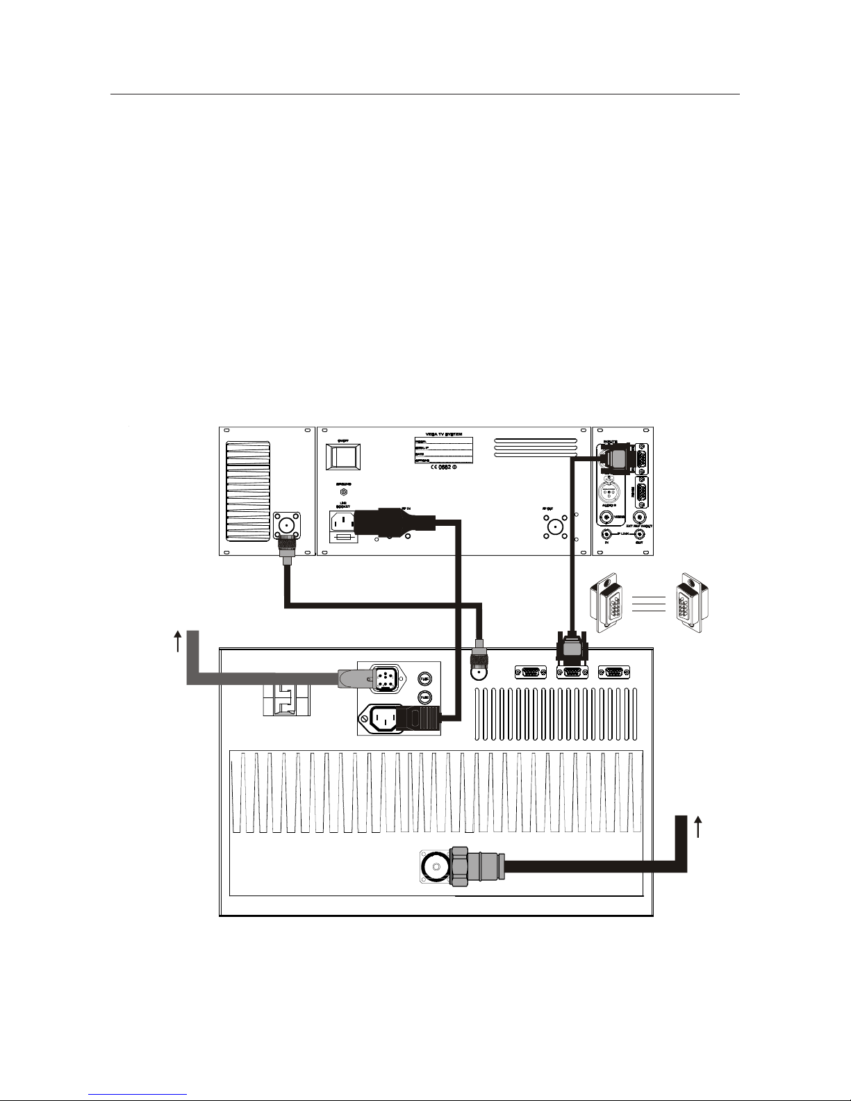
2.3 CONNECTION WITH VEGA TV TRANSMITTER
AGC
1
2
8
5
8
4
TV AMPLIFIER VEGA
BREAKER
AC 200V OUT
RS485 TELEMEASURES
AC 400V IN
RF OUT
RF IN
To ELECTRIC NETWORK
To ANTENNA
102
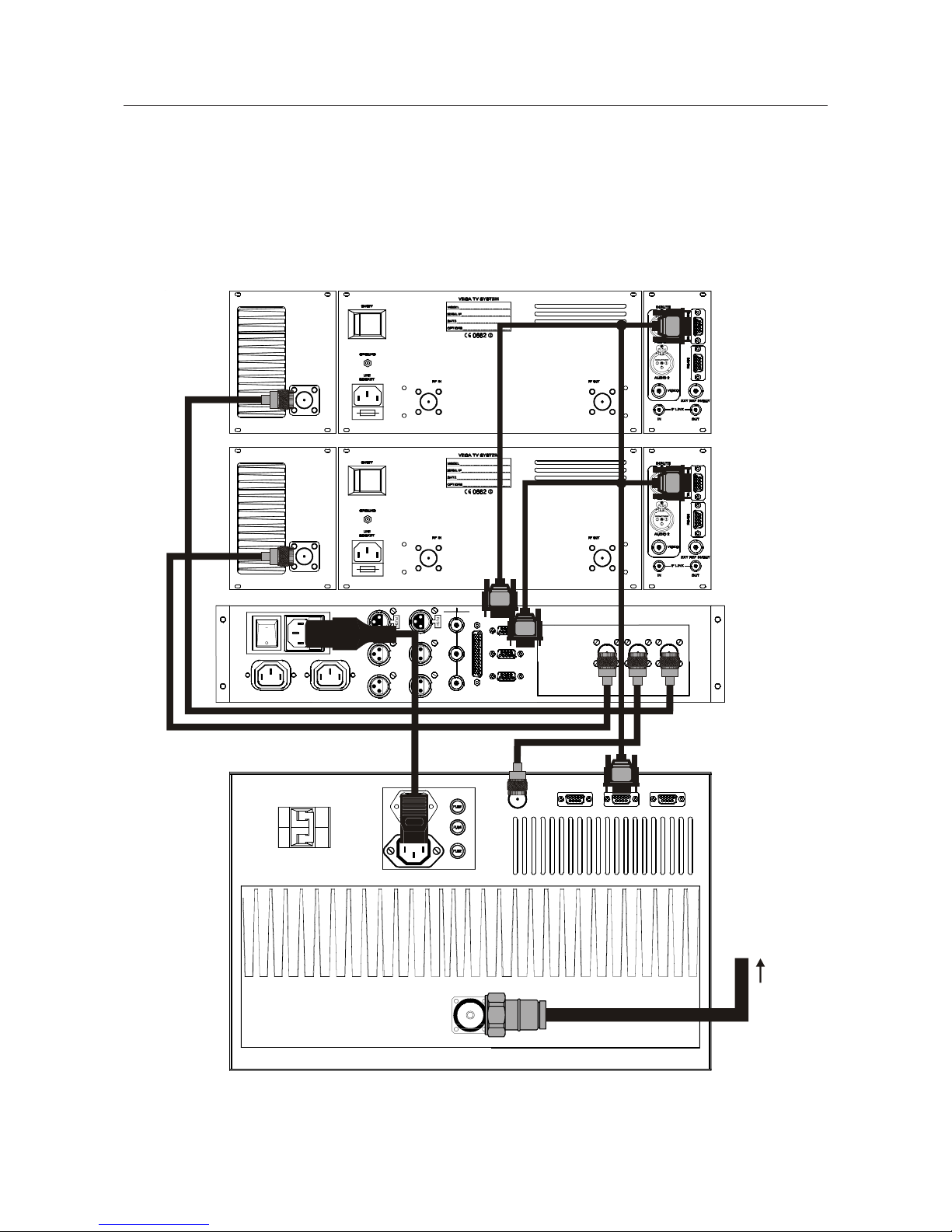
2.4 ST AND-ALONE AMPLIFIER CONFIGURA TION IN DUAL DRIVE VERSION
OUT
MAIN
VIDEO
OUT
AUX
AUXMAIN
GND
LEFT
OUT
AUX
LEFT
MAIN
LEFT
OUT
IN
RIGHT
OUT
AUX
RIGHT
MAIN
OUT
RIGHT
IN
IN
AUX
MAIN
IN
19kHz
OUT
DIRECT
REMOTE
IN
RF AUX IN RF OUT RF MAIN IN
AUX CTRL
RS232/485
REMOTE
MAIN CTRL
BREAKER
AC 200V OUT
AC 400V IN
RF OUT
AGCRS485 TELEMEASURESRF IN
To ANTEN NA
103
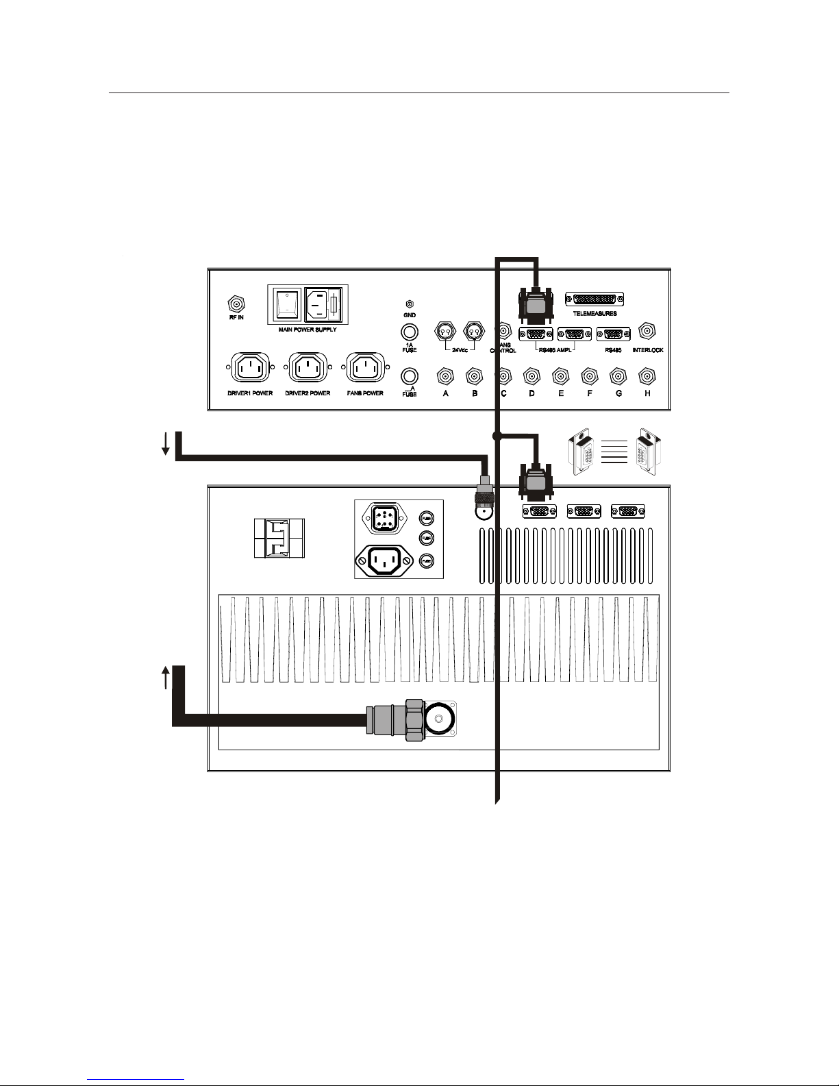
2.5 SLA VE MULTI-AMPLIFIER CONFIGURATION WITH AMPLIFIER CONTROL
BREAKER
AC 200V OUT
AC 400V IN
RF OUT
AGCRS485 TELEMEASURES
2
3
5
2
3
5
AMPLIFIER CONTRO L AMPLIFIER
RF IN
To COMBINER
7
8
7
8
From SPLITTER
104
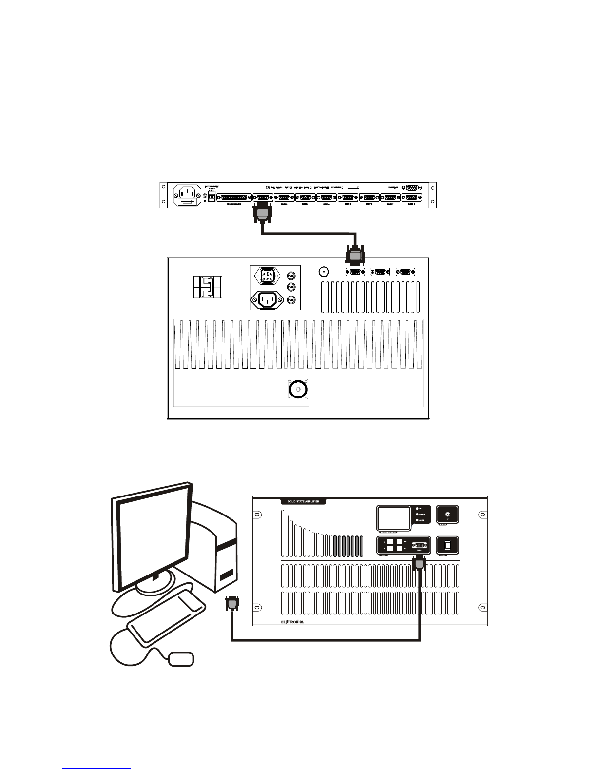
2.7 ST AND-ALONE AMPLIFIER CONFIGURA TION WITH DIRECT PC CONNECTION
2.6 ST AND-ALONE AMPLIFIER CONFIGURA TION WITH ELETTRONIKA RCU
SERIAL PORT
BREAKER
AC 200V OUT
AC 400V IN
RF OUT
AGCRS485 TELEMEASURESRF IN
105
Section 3 - Operation
Contents:
3.1 Operation
3.2 Display
3.3 Menus
3.4 Firmware upgrade
106
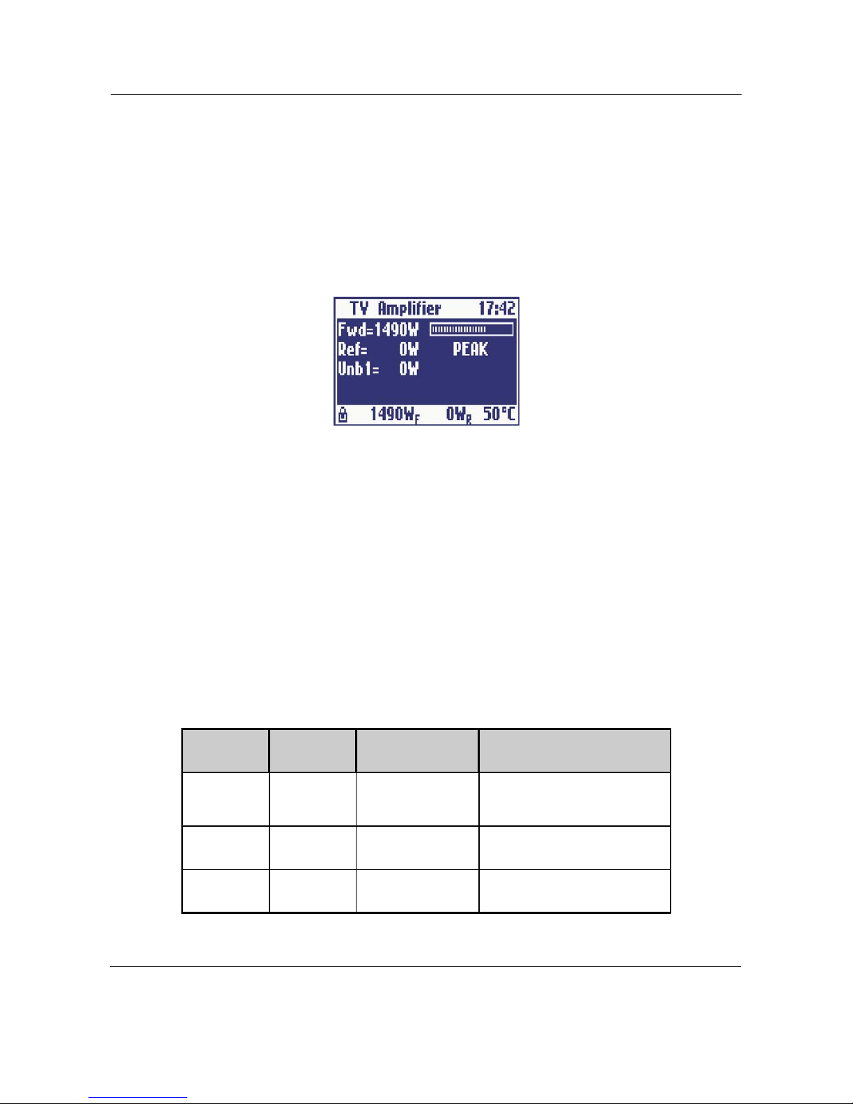
3.1 OPERA TION
At startup, after initial image, the display shows the main screen with the RF powers as below:
The user may turn on and off the amplifier by means of the switch on the front panel. The control board turns
on all the power supplies, the exciter (if any), and internal cooling fans. While the amplifier is working, the
micro-controller monitors continuously the most important parameters: power supply voltages, absorbed
currents, high power zone temperature, forward and reflected powers, unbalances (if any). Each measure is
associated to a maximum threshold beyond which the amplifier is immediately put in protection status by
turning off one or more power supply , depending on the failed block. In order to prevent a temporary problem
to trigger a definitive protection status, the failed block is turned on again, after some seconds, for up to five
times. If it goes beyond the protection threshold for more than five times, it is declared as F AILED and it will
no longer be turned on. In this case, the amplifier will have to be turned off manually by means of the switch on
the front panel, then turned on again after performing the needed maintenance.
On the front panel there are also three LEDs labelled ON, REMOTE and ALARM. Their meanings are
explained in T able 1.
T able 1: Meanings of the three LEDs on the front panel
1
Screenshots in this manual are indicative, so they can be different from those on your equipment.
LED COLOUR MEANING MEANING WHEN BLINKING
ON Green The amplifier is on
The amplifier has been turned on
locally but it has been turned off by
remote
REMOTE Yellow
Remo te co ntrol is
enabled
It n ever blin ks
ALARM Red An alarm is present It never blinks
 Loading...