

Electronics Research, Inc. 100A Series, 100A-2F-HW, 100A-2F, 100A-1M Installation Instructions Manual
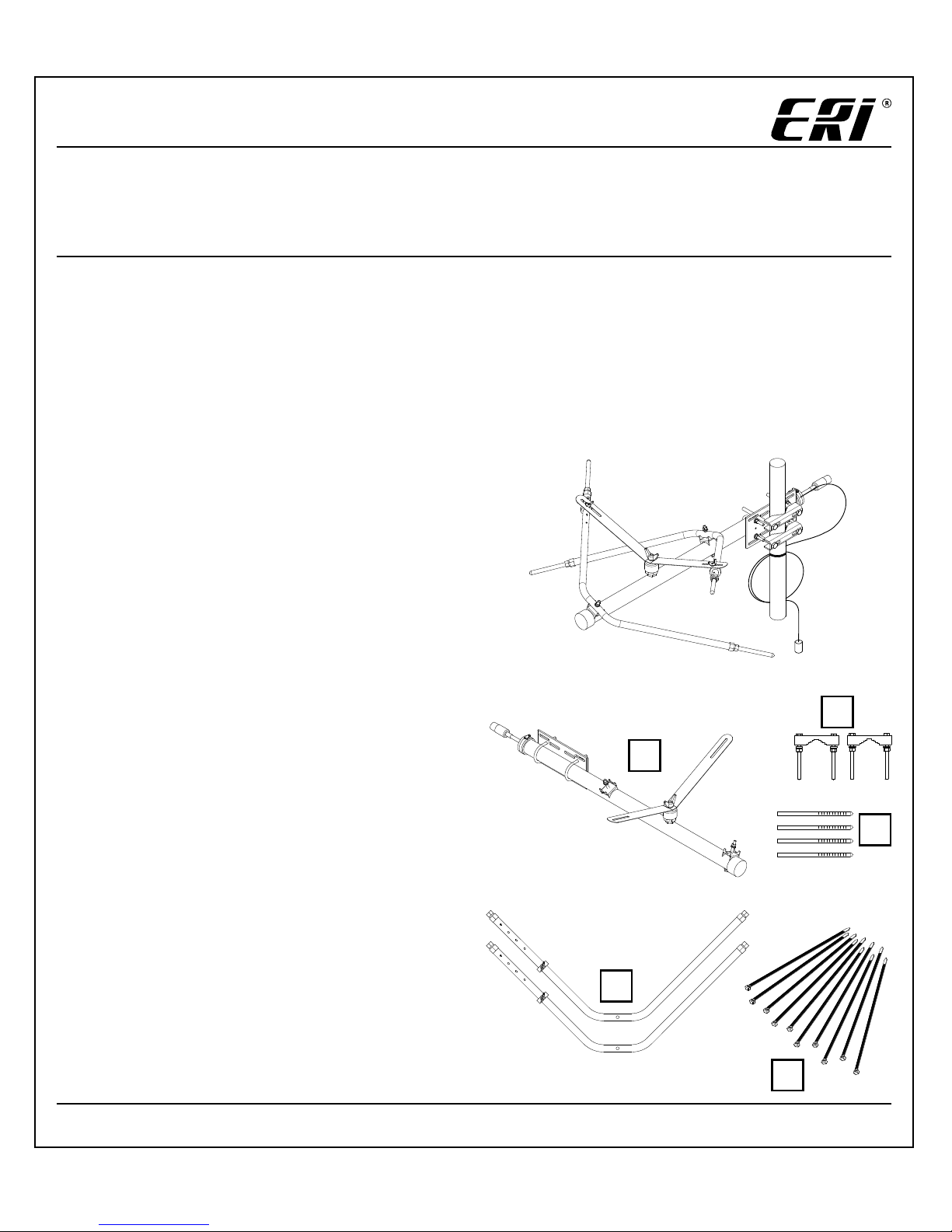
100A Series Low Power FM Antenna
Types 100A-1M, 100A-2F, 100A-2F-HW
20100326001_AEN Revision 03
Electronics Research, Inc. | 7777 Gardner Road, Chandler, IN 47610 USA | www.eriinc.com | +1 (812) 925-60000
Installation Instructions
Notice
The installation, maintenance, or removal of antenna systems requires qualied, experienced personnel.
ERI installation instructions are written for such personnel. Antenna systems should be inspected once a
year by qualied personnel to verify proper installation, maintenance, and condition of equipment. ERI
disclaims any liability or responsibility for the results of improper installation practices.
READ THE INSTRUCTIONS THOROUGHLY BEFORE ASSEMBLY
Preparation
Before beginning the assembly and installation of
the 100A Series antenna system, make sure all parts
are present.
Tools Required (not included):
5/32 Inch Allen wrench •
9/16 Inch Open-end wrench •
Adjustable wrench (15/16 Inch Capacity) •
Ruler or Tape Measure accurate to 1/16 inch (0.15 •
cm)
NOTE: A torque wrench adaptable to tools
mentioned above will be helpful in the installation
process.
Parts*
Element Boom Assembly (qty 1)1.
Element Arm Assembly (qty 2)2.
Arm Extender Kit (qty 4)3.
Universal Mounting Clamps (qty 2)4.
Cable Ties (qty 10)5.
* The parts listed are for the 100A-1M. For type numbers 100A-2F
and 100A-2F-HW, an additional 100A element (as described
above) and a PD100A power divider are included.
1
2
3
4
5
2
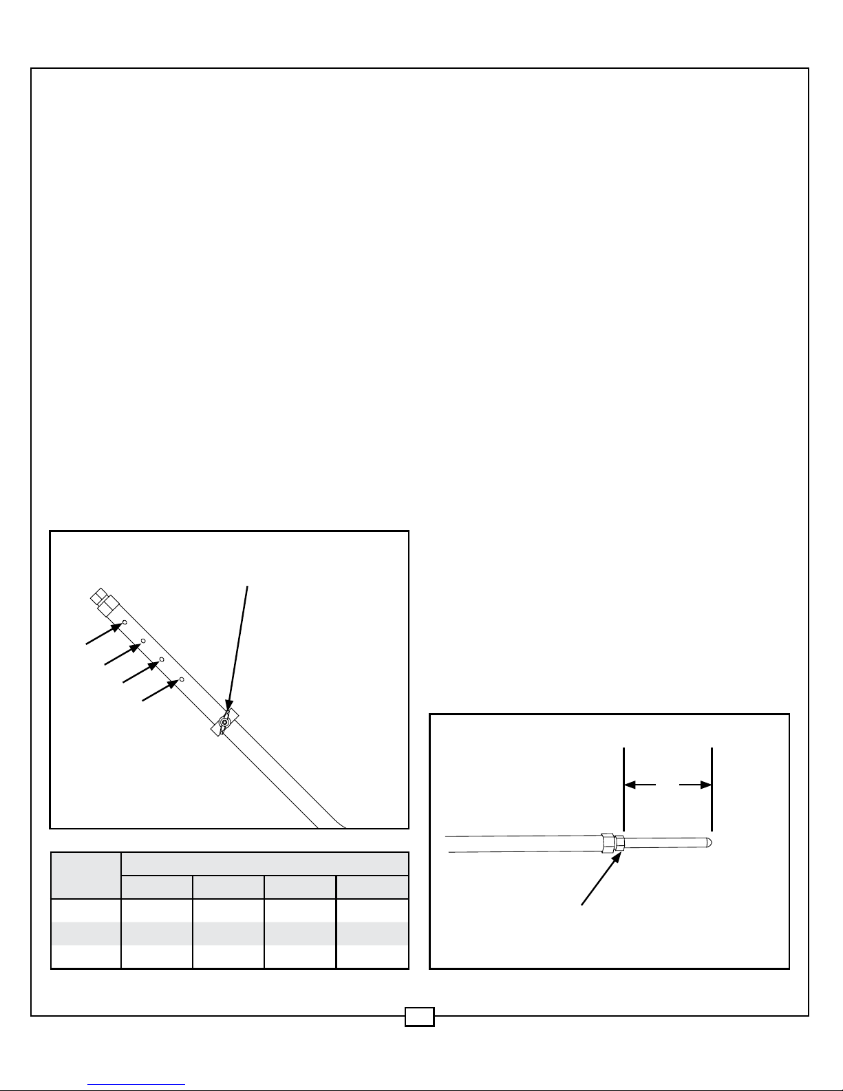
Step 1: Secure the Feed Grounding Ring
to the Element Arm
To ensure a good electrical connection between 1.
the Grounding Ring and the Element Arm,
temporarily remove the 5/16 wing-nut, lockwasher and at-washers from the grounding
set-screw.
Next, locate your frequency range and antenna 2.
type number in the table below and nd the
corresponding grounding ring position (1, 2, 3,
or 4).
Now slide the Grounding Ring over the spot 3.
that corresponds to the correct grounding ring
position.
Using a 5/32 inch Allen wrench, tighten the set-4.
screw to 11 lbf·ft (15 N·m) torque imbedding the
screw into the Element Arm.
Repeat Step 1 for the remaining Element Arm 5.
assemblies.
Step 2: Install Arm Extenders
Loosen the 15/16 inch End Fastener (brass nut 1.
found at each end of both element arms) to the
point where the Arm Extenders can be freely
inserted. NOTE: As shipped, the element arm’s
15/16 inch end fasteners are pre-tightened
in order to trap the assemblies’ internal
compression ring. Caution should be exercised
while performing this operation. Removing
the nut could result in the loss of the internal
compression ring.
Insert an Arm Extender into each end of the 2.
Element Arms.
Locate your frequency range and antenna type 3.
number in the Tip Length table (right) and
nd the corresponding Tip Length "L". NOTE:
Be certain that you are using the length that
corresponds both to your antenna frequency
and type number.
Position each Arm Extender so that the exposed 4.
length is "L" (from the table). This Length is
measured from the top of the 15/16 inch
clamping nut to the tip of arm extender. NOTE:
The extender tip length is critical and must be
set correctly.
Once the Arm Extender is set, secure the 5.
connection with an adjustable wrench and
torque to 15 lbf·ft (21 N·m) .
5/16 wing-nut, lock-washer
and at-washers
1
2
3
Step 1
4
Step 2
L
15/16 End Fastener
Type
Number
Grounding Ring Position
1 2 3 4
100A-1M 96.5 - 108.0 — 92.5 - 96.4 87.5 - 92.4
100A-2F 96.5 - 108.0 — 92.5 - 96.4 87.5 - 92.4
100A-2F-HW 97.5 - 108.0 87.5 - 89.4 89.5 - 97.4 —
3
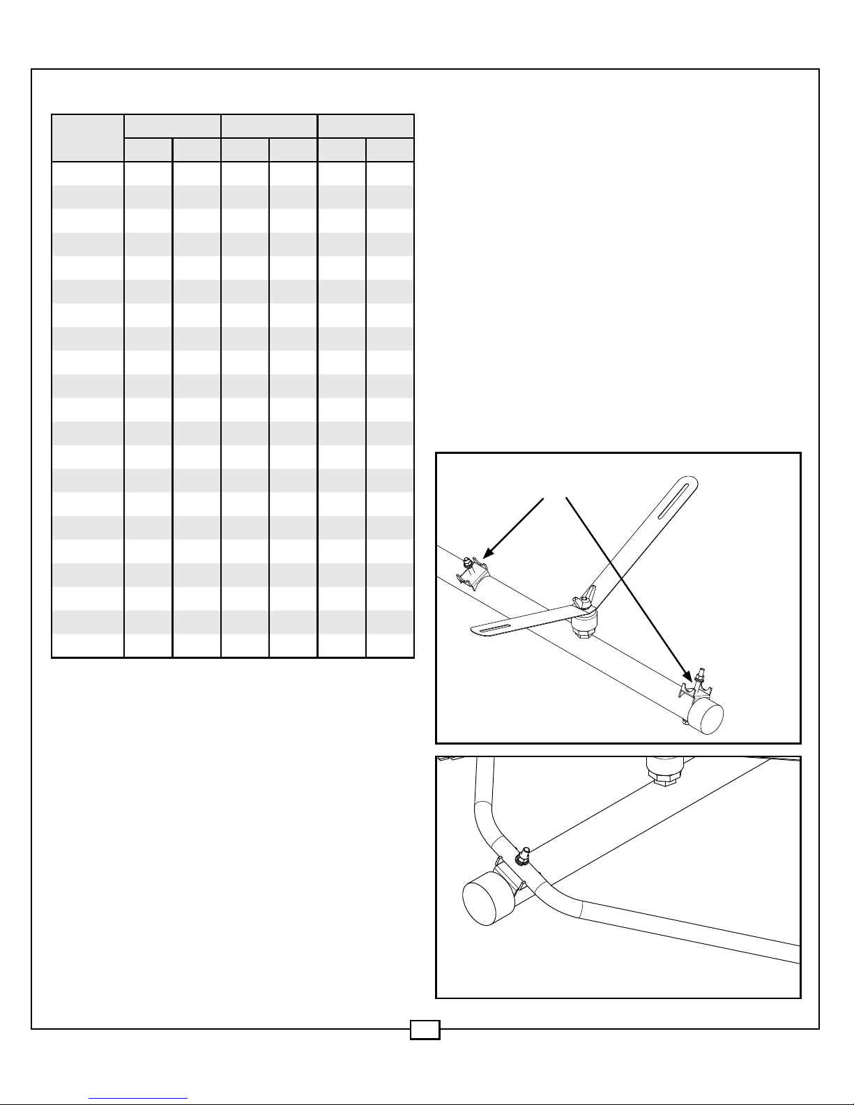
Step 3: Mount the Element Arms to the
Element Boom
Remove the mounting hardware (stainless steel 1.
3/8 at-washer, lock-washer and nut) from both
Boom Cradle Brackets. (Step 3 a)
Place one Element Arm into each Boom Cradle 2.
Bracket with the Feed Strap Stud pointing up.
(Step 3 b)
Secure the arm to the threaded post using the 3.
mounting hardware (stainless steel 3/8 atwasher, lock-washer and nut).
Tighten the cradle nut until the cradle’s sharp 4.
grounding point is rmly seated into the Element
Arm material and the lock washer is compressed,
approximately 12 lbf·ft (16 N·m) torque.
Step 3b
Step 3a
Boom Cradle Brackets
Tip Length, ‘L’
Frequency
Range
100A-1M 100A-2F 100A-2F-HW
inch cm inch cm inch cm
107.5 - 108.0 2 5/16 5.87 2 1/4 5.72 1 7/8 4.76
106.5 - 107.4 2 3/4 6.99 2 5/8 6.67 2 1/8 5.40
105.5 - 106.4 3 7.62 3 7.62 2 1/2 6.35
104.5 - 105.4 3 5/16 8.41 3 3/8 8.57 2 29/32 7.38
103.5 - 104.4 3 11/16 9.37 3 3/4 9.53 3 5/16 8.41
102.5 - 103.4 4 10.16 4 1/8 10.48 3 11/16 9.37
101.5 - 102.4 4 3/8 11.11 4 9/16 11.59 4 1/16 10.32
100.5 - 101.4 4 5/8 11.75 4 7/8 12.38 4 1/2 11.43
99.5 - 100.4 5 12.7 5 3/16 13.18 4 7/8 12.38
98.5 - 99.4 5 5/16 13.49 5 9/16 14.13 5 3/16 13.18
97.5 - 98.4 5 5/8 14.29 5 7/8 14.92 5 19/32 14.21
96.5 - 97.4 6 1/16 15.4 6 1/4 15.88 5 11/16 14.45
95.5 - 96.4 6 3/16 15.72 6 5/16 16.03 6 1/16 15.40
94.5 - 95.4 6 9/16 16.67 6 5/8 16.83 6 7/16 16.35
93.5 - 94.4 7 1/8 18.1 7 17.78 6 13/16 17.30
92.5 - 93.4 7 5/16 18.57 7 3/8 18.73 7 3/16 18.26
91.5 - 92.4 7 1/2 19.05 7 1/2 19.05 7 3/16 18.26
90.5 - 91.4 7 7/8 20 7 7/8 20 8 1/16 20.48
89.5 - 90.4 8 5/16 21.11 8 5/16 21.11 8 1/2 21.59
88.5 - 89.4 8 3/4 22.23 8 3/4 22.23 9 1/8 23.18
87.5 - 88.4 9 3/16 23.34 9 3/16 23.34 9 5/8 24.45

4
Step 5: Secure the Antenna to its
support structure
A Universal Mounting Clamp Kit is included with
the antenna for ease of mounting to the tower
leg. The kit generally eliminates the need for any
additional brackets, however chain and “J” bolts can
be ordered for larger pole installations.
Step 5
Step 4: Attach the Feed Strap
Loosen the feed insulator wing-nut and 1.
swing the strap from the shipped position
(perpendicular to the Boom) to where the
strap engages the Grounding Ring’s protruding
threaded studs (set-screws).
Fasten the strap to the two threaded studs; a 2.
proper connection is obtained when the strap
is sandwiched between the two stainless-steel
at washers, lock washer and 5/16 inch wing-nut
removed in Step 1. The Grounding Ring WingNut is secured using 8 lbf·ft (11 N·m) of torque
applied to the wing-nut.
Hand tighten the Insulator wing nut taking care 3.
not to exceed the 3 lbf·ft (4 N·m) torque rating.
Step 4
Feed insulator wing-nut
Grounding Ring Wing-nut

5
Step 6: Connect the antenna feed to the
transmission Feed
Connect the antenna feed pigtail to the 1.
transmission feed.
To prevent water and other contaminants from 2.
seeping into the joint, wrap the connection with
a good quality rubber electrical tape.
To prevent cable strain, excess cable should be 3.
spooled and tied down. The 11’ pigtail feed of
the 100A Series Antenna can be coiled into a 5 in.
diameter, however never exceed the maximum
1-3/4 in. bending radius of the cable. NOTE:
Failure to properly install and secure the cable
might allow wind vibration to destroy antenna
connections. Use the 10 furnished Cable Ties to
spool and tie the cable to the tower.
Step 6

6
Bay Spacing
For Antenna Type Numbers 100A-2F and
100A-2F-HW
Use the Bay Spacing table (right) and repeat steps
1 through 6 for the additional element. Install the
PD100A power divider according to the diagrams
above and the Bay Spacing table (right).
The Power Divider is secured to the tower using
stainless steel hose clamps furnished with the
Power Divider. Seal power divider connections with
electrical tape.
PD100A
(Power Divider)
Hose
Clamps
Weep
Hole

7
Bay Spacing
Frequency
Range
100A-2F 100A-2F-HW
inch cm inch cm
107.5 - 108.0 109 1/4 277.5 54 5/8 138.75
106.5 - 107.4 110 5/16 280.19 55 5/32 140.10
105.5 - 106.4 111 3/8 282.89 55 11/16 141.45
104.5 - 105.4 112 3/8 285.43 56 3/16 142.72
103.5 - 104.4 113 1/2 288.29 56 3/4 144.15
102.5 - 103.4 114 9/16 290.99 57 9/32 145.49
101.5 - 102.4 115 3/4 294.01 57 7/8 147.00
100.5 - 101.4 116 7/8 296.86 58 7/16 148.43
99.5 - 100.4 118 299.72 59 149.86
98.5 - 99.4 119 1/4 302.9 59 5/8 151.45
97.5 - 98.4 120 7/16 305.91 60 7/32 152.96
96.5 - 97.4 122 5/8 311.47 61 5/16 155.73
95.5 - 96.4 122 15/16 312.26 61 15/32 156.13
94.5 - 95.4 124 1/4 315.6 62 1/8 157.80
93.5 - 94.4 125 1/2 318.77 62 3/4 159.39
92.5 - 93.4 126 7/8 322.26 63 7/16 161.13
91.5 - 92.4 128 1/4 325.76 64 1/8 162.88
90.5 - 91.4 129 11/16 329.41 64 27/32 164.70
89.5 - 90.4 131 1/8 333.06 65 9/16 166.53
88.5 - 89.4 132 5/8 336.87 66 5/16 168.43
87.5 - 88.4 134 1/8 340.64 67 1/16 170.34
Pre-Deployment Checklist
[ ] The mounting hardware ts the diameter of the
tower leg.
[ ] The Grounding Ring is installed properly
according to the table.
[ ] All components are securely connected..
[ ] The feed cable rated capacity is not exceeded and
is correctly paired to the rating of the Antenna.
[ ] Electrical tape is used at the connection point
between the feed pigtail (antenna feed lead-in)
and the feed-line connector.
[ ] If a feed cable adapter is required, the gender is
correct.
[ ] Inspect the element’s feed pigtail (antenna feed
lead-in) for connector damage, cable kinks,
or pinching. Do not install if damaged; call
Electronics Research Inc for assistance.
Attention Installer
Do not install the Antenna near other tower 1.
mounted Antennas. Always mount the Antenna’s
Boom pointing in the direction of desired
coverage.
Always mount the antenna with the Strap 2.
Insulator pointing up.
Ensure the feed pigtail stays coiled until you 3.
reach the tower location to mount the antenna.
If a 2-Bay* conguration is being installed, 4.
mount the elements directly above one another
using the bay spacing distance furnished in the
Bay Spacing table.
Always tie down loose cable to the tower using 5.
quality tie-down material.
The length of certain horizontal and diagonal 6.
tower members can create resonant conditions
that may impact antenna VSWR performance.
If possible, avoid 30” to 60” dimensions
corresponding to ¼ and ½ wavelengths.
* PD100A power divider and second 100A element is
required for the 2-Bay arrangement. The Power Divider
is secured to the tower using stainless steel hose clamps
furnished with the Power Divider. Seal power divider
connections with electrical tape.

Electronics Research, Inc. | 7777 Gardner Road, Chandler, IN 47610 USA | www.eriinc.com | +1 (812) 925-60000
All designs, specications, and availabilities
of products and services presented in this
publication are subject to change without notice.
Publication 20100326001_AEN Revision 03
(2011-02-04) Copyright © 2011 Electronics
Research, Inc. Chandler, IN 47610 USA
For Technical Support call 877 ERI-LINE or +1 812 925-6000,
or visit our website at www.eriinc.com
 Loading...