

Page 1
Single Motor (Hub) and Remote
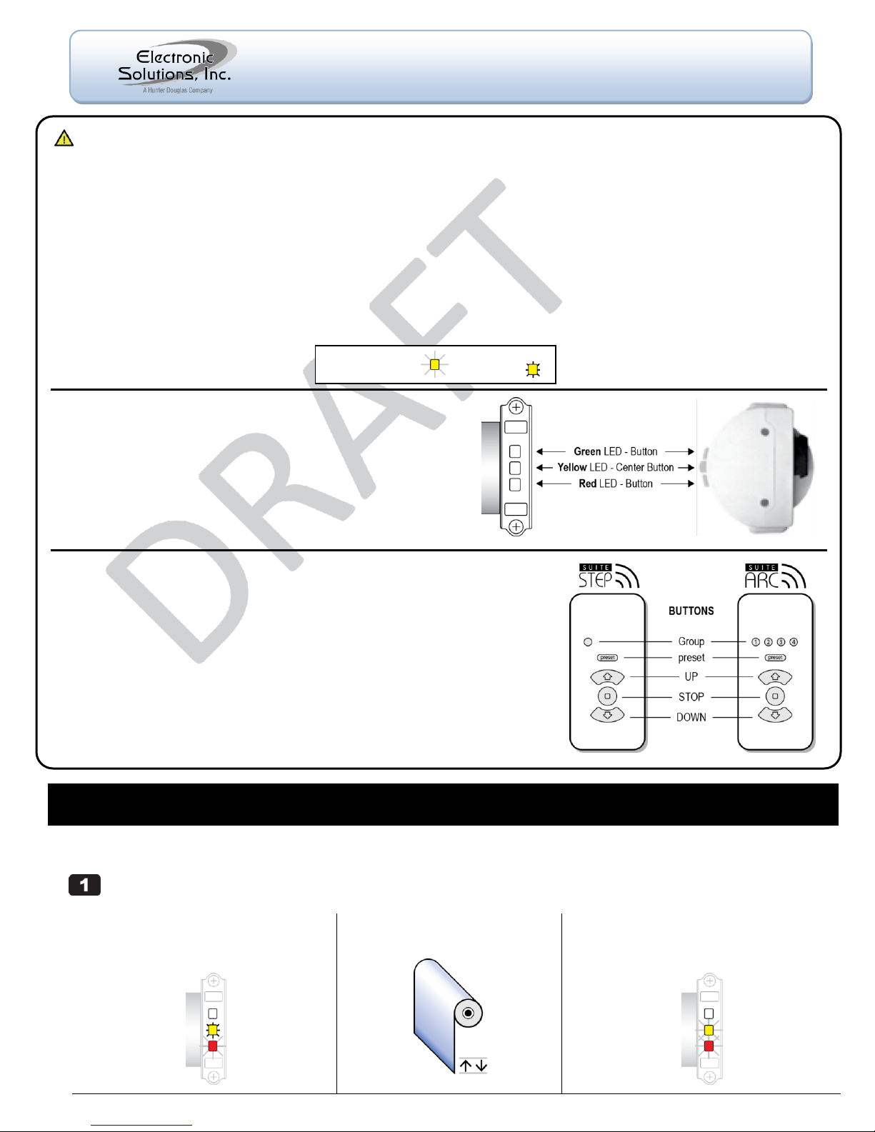
(a) Connect AC power to the motor.
On motor, Yellow LED is solid and Red LED is
flashing (indicates end limits are not set).2
(b) Wait until motor jogs twice.
Could take up to 3 minutes.
(c) Motor is now the Hub motor.
Yellow LED begins flashing for 60 seconds
(indicates Network Invite Mode).3
Important Installation Information
When shipped, the remote is in Setup Mode to facilitate creation of a motor network.
When network creation is finished and ready for the end user, you must exit Setup Mode on the remote.
For best RF performance, the antenna on the motor should maintain as much separation from a conductive surface as possible.
Glossary
Hub Motor - Special designation for the first motor powered up. All commands to additional motors are routed through the Hub motor.
Jog Once - Motor moves a short distance in one direction.
Jog Twice - Motor moves a short distance in two directions.
Remote - The RF transceiver used to set up and operate motors.
Asleep - The default state of a remote is ―asleep‖ — no LEDs are lit. ―Wake Up‖ remote: press and release the UP or DOWN button.
Group - A collection of up to four motors controlled by Group 1, 2, 3, or 4 on an Arc transceiver or Group 1 on a Step transceiver.
LED - Light-emitting diode. Both the remote and the motor head have LEDs in three colors.
Blink - A single on/off of an LED.
Flash - LED turns on and off continuously.
M40/50RF Motor
The M40/50RF motor is equipped with radio frequency technology
and has three buttons with internal LEDs that provide visual
feedback during setup and operation.
Green LED – Button operates the motor in one direction.
Yellow LED – Center Button is used for motor administration.
Red LED – Button operates the motor in the other direction.
SUITE Remote
The SUITE Remote is equipped with radio frequency technology for wireless control
of all ESI RF-enabled motors.
The SUITE Step remote controls one group of up to four motors.
The SUITE Arc remote controls four groups of up to four motors each, for a total of sixteen motors.
Wake Up the Remote
The remote must be ―awake‖ to send or receive commands.
To wake up a remote that is ―asleep‖ (no LEDs are lit):
Press and release the UP or DOWN button.
NOTE: When no buttons are pressed, the remote goes to sleep after 10 seconds
while in User Mode, or after 60 seconds while in Setup Mode.
Blink or Flash = Solid =
M40/50RF System
Quick Setup Guide
© 2011 Electronic Solutions, Inc.
1355 Horizon Avenue, Lafayette, CO 80026 U.S.A.
Tel: (303) 469-9322 www.elec-solutions.com
IMPORTANT: Prior to motor network setup, install batteries into the SUITE Remote and wait for the LEDs to go out (“asleep”).
Create the Hub Motor — Power up one factory default motor which automatically establishes it as the Hub.
1
Page 2
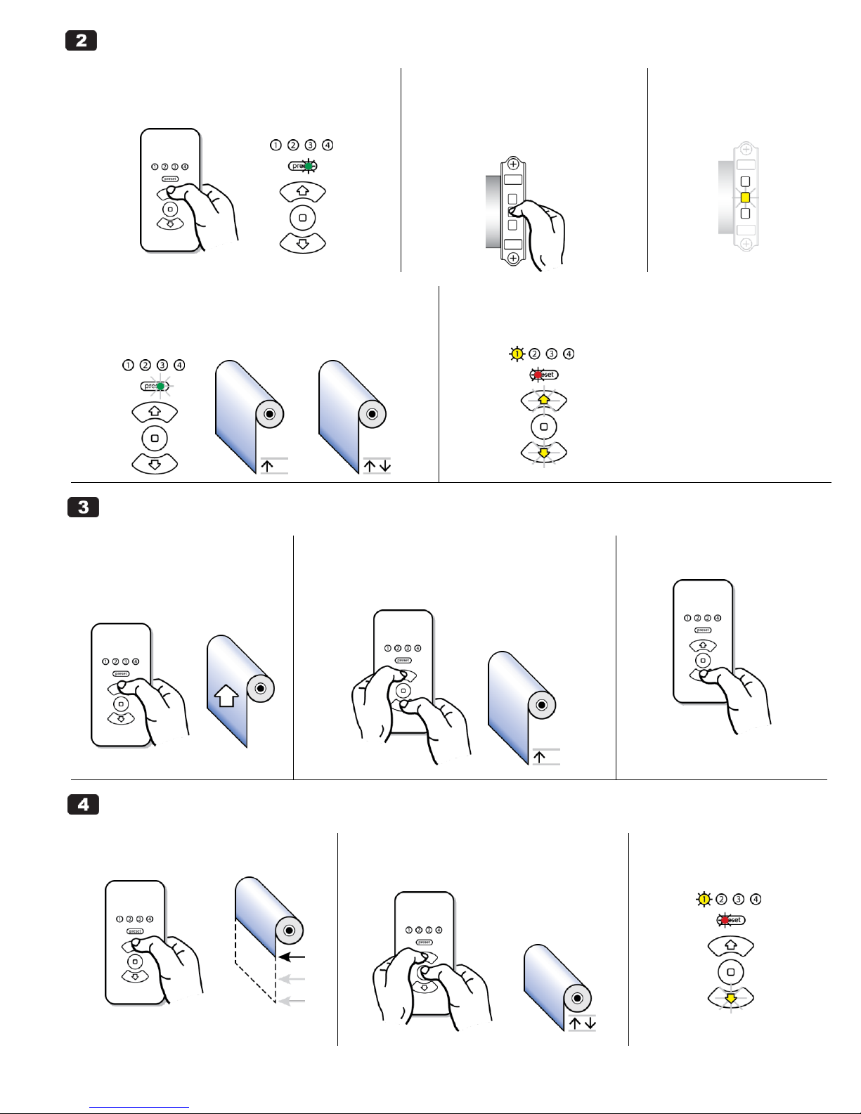
Join the Remote to the Hub Motor
(a) “Wake up” the remote if no LEDs are lit (asleep).
Press and release the UP or DOWN button.
Green “preset” LED is solid (Network Search Mode).
4
(b) Put Hub motor into Network Invite
Mode.
NOTE: if the Yellow LED on the motor is
flashing, Skip to Step 2 (d).
Press and release the Center button once.
(c) On the Hub motor.
Yellow LED flashes for 60
seconds to indicate new
devices may join.
(d) Remote automatically joins the Hub and forms a
network.
Green “preset” LED blinks once, and Hub motor jogs once, then jogs
twice.
(e) Remote is in Setup Mode.
Red LED under “preset” is solid, and Yellow LED under Group 1 is solid.
The UP and DOWN buttons are flashing (indicates no end limits are set).
(a) Verify travel direction.
Press the UP or DOWN button.
If the shade moves as expected,
skip to Step 4.
(b) Toggle the motor direction.
Simultaneously press and hold the UP and DOWN buttons
for 5 seconds until the motor jogs once.
Motor direction is now reversed.
(c) Verify the direction change.
Press the UP or DOWN button.
(a) Adjust shade to Upper limit position.
Press and hold the UP button.
(b) Set the Upper end limit.
Simultaneously press and hold STOP and UP until
motor jogs twice (approximately 2 seconds).
(c) Upper end limit is set.
Yellow LED on UP button turns
off.
Toggle Motor Direction — Check the motor travel direction using the remote.
Set Limits
M40/50RF System September 2011, rev 2 - DRAFT © 2011 Electronic Solutions, Inc. Page 2 of 7
Page 3
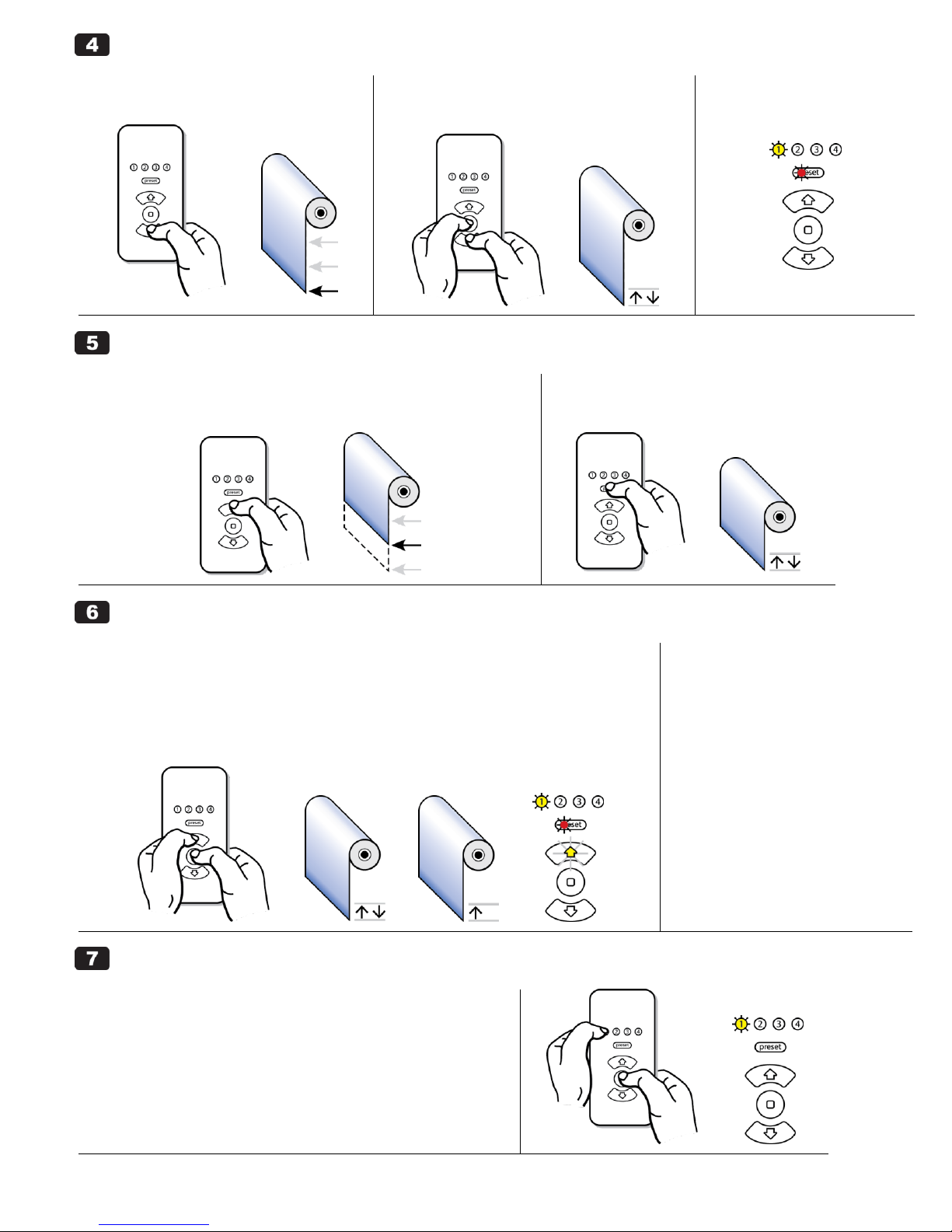
Set Limits (continued)
(d) Adjust shade to Lower limit position.
Press and hold the DOWN button.
(e) Set the Lower end limit.
Simultaneously press and hold STOP and DOWN
until motor jogs twice (approximately 2 seconds).
(f) Lower end limit is set.
Yellow LED on DOWN button
turns off.
(a) Adjust shade to desired “preset” position.
NOTE: Both end limits must be set prior to setting a ―preset‖ position.
Press and hold the UP (or DOWN) button.
(b) Set the “preset.”
Press and hold “preset” until motor jogs twice
(approximately 5 seconds) then release.
(a) Adjust the Upper or Lower end limits.
NOTE: To set an end limit outside of a current end limit, you must clear that end limit first.
Clear Upper Limit:
Simultaneously press and hold STOP and UP until motor jogs twice, then jogs once (approximately 5
seconds), then release.
The UP button flashes to show its limit is cleared.
Clear Lower Limit: repeat the above two instructions using the DOWN button (instead of UP).
(b) Set the new Upper or Lower
end limit.
UPPER: see Step 4 (a), (b), (c).
LOWER: see Step 4 (d), (e), (f).
------------------------------------------------
(c) Adjust the “preset” limit.
NOTE: A ―preset‖ cannot be cleared
using the remote, only readjusted.
Follow the instructions in Step 5.
NOTE: If this is a single motor installation, complete Step 7 now,
otherwise continue with Step 8 for a multiple motor installation.
(a) On the remote, you must exit Setup Mode and put the
remote into User Mode after the installation is complete.
Hold “1” and briefly press and release STOP.
Red LED under “preset” turns off (remote is now in User Mode).
Set “preset” (OPTIONAL)
Adjust Limits / Clear Limits
Finish the Installation
M40/50RF System September 2011, rev 2 - DRAFT © 2011 Electronic Solutions, Inc. Page 3 of 7
Page 4

Add Additional Motors
(a) “Wake up” the remote if no
LEDs are lit (asleep).
Press and release the UP or DOWN
button.
(b) Setup Mode on the remote.
Red LED under “preset” is solid.
Yellow LED under Group 1 is solid.
(c) Start network invite.
Press and release the STOP button.
Green LED under “preset” flashes for up to 60 seconds while
the remote looks for devices to join.
(d) Connect AC power to the next
motor.
Yellow LED is solid and Red LED is
flashing (indicates end limits are not set).
(e) Within a few seconds, the next
motor joins the network.
Next motor jogs once.
Hub motor jogs once.
Next motor: Hub motor:
(f) On the remote:
Red LED under “preset” is solid.
Yellow LED under Group 2 is solid if it is the 2nd
motor (“3” if it is the 3rd motor and so on).
The UP and DOWN buttons are flashing
(indicates no end limits are set).
(a) Make sure the correct Group Number is selected on the remote: for the 2nd motor, for the 3rd motor, and so on.
See Steps 3, 4, 5, and 6.
(b) Repeat Steps 8 and 9 for each new motor until all motors are installed.
Each Group button on a remote can be assigned up to four motors. The SUITE Step remote (one
Group button) can control up to four motors. The SUITE Arc remote (four Group buttons) can
control up to 16 motors.
SUITE Arc remote
As motors are installed (powered up) into a network, they populate into the Group Number table
in sequential order. Motor #1 becomes the first motor in Group 1, Motor #2 becomes the first
motor in Group 2 and so on.
Continuing, Motor #5 becomes the second motor in Group 1.
Join Additional Motors to the Network
Add up to 4 motors when using a SUITE Step remote. Add up to 16 motors when using a SUITE Arc remote.
IMPORTANT: Install the next motor but DO NOT apply power yet. Be sure the remote is in Setup Mode.
Toggle Motor Direction — Set Limits — Adjust Limits / Clear Limits
Motor Group Number Assignment — Move a motor to a different Group (SUITE Arc remote only).
M40/50RF System September 2011, rev 2 - DRAFT © 2011 Electronic Solutions, Inc. Page 4 of 7
Page 5

(a) Select a motor in a group.
Press a Group Number button repeatedly to cycle through motors in
that group. For example, press the Group 1 button two times to
select the second motor in that group.
Selected motor jogs once.
NOTE: The Hub motor will always jog twice when selected.
If a Group is full on the remote (4 motors), you cannot move a motor into it.
(b) Change a motor’s group number assignment.
Press and hold the new Group Number button, for example, Group 3,
for approximately 5 seconds until the selected motor jogs once (if the
selected motor is the Hub motor, it will jog twice).
The motor has now moved into the first available position within the
new group.
NOTE: In Setup Mode, only one motor can be selected at a time. In User
Mode, one or more groups of motors can be selected.
(a) On the remote, you must exit Setup Mode and put the
remote into “User Mode” after the installation is complete.
Hold “1” and briefly press and release STOP.
Red LED under “preset” turns off (remote is now in User Mode).
Enter Setup Mode for network configuration.
NOTE: Remote must be awake and must be in User Mode.
Simultaneously press and hold “1” and STOP for 5 seconds.
Red LED under “preset” turns solid, and Yellow LED under Group 1 turns solid.
Exit Setup Mode and put the remote into User Mode.
NOTE: Remote must be awake.
Hold “1” and briefly press and release STOP.
Red LED under “preset” turns off.
Motor Group Number Assignment (continued)
Finish the Installation
Enter SETUP MODE (remote)
Exit SETUP MODE (remote)
M40/50RF System September 2011, rev 2 - DRAFT © 2011 Electronic Solutions, Inc. Page 5 of 7
Page 6

1. Clear Limits
(a) Press and hold the Center button for 10 seconds.
(b) Red LED starts flashing.
End limits are now cleared.
2. Clear Network Information
(a) Press the Center button 3 times within 1 second.
(b) All motor LEDs turn off for 5 seconds, then the Yellow LED flashes for 60 seconds to
indicate new devices may join (Network Invite Mode).
(c) Motor will join an existing network or become a Hub motor if no network is detected.
NOTE: If you clear the Network Information on the Hub motor, you will lose the
ability to administer the network; however, you can still control the remaining
motors in the network. To re-create a network, you must Reset the remote,
then start over, beginning with Step 1 ―Create the Hub Motor.‖
3 x
Reboot / Reset
NOTE: Remote must be awake and in Setup Mode to perform a reboot* or reset.
- A “reboot” retains all network and device information and the remote rejoins the network.
- A “reset” clears all network and device information (factory default).
Press and hold “preset” and STOP — after 2 seconds, UP and DOWN turn on solid.
To REBOOT: Release “preset” and STOP when the UP and DOWN LEDs are on solid.
The remote enters Setup Mode immediately after rebooting.
To RESET: Release “preset” and STOP after the UP and DOWN LEDs go out (about 5 seconds).
The remote enters Network Search Mode immediately after resetting.
* A reboot functions the same as if the batteries were removed, then reinstalled or replaced. A reboot is
typically used if the remote has communication errors or operational errors with the network.
-----------------------------------------------------------------------------------------------------------------
Battery Installation
Required:
three AAAA batteries.
screwdriver to remove the back cover.
Install the Batteries:
Remove the remote’s back cover.
Install fresh batteries with the plus (+)
side oriented as shown by the
illustrations on the circuit board.
Replace the back cover.
Remote, with back cover removed.
REBOOT (goes into Setup Mode):
RESET (goes into Network Search Mode):
Delete a motor’s network information and remove the motor from the network.
NOTE: Remote must be awake and in Setup Mode.
On the motor:
Press the Center button 3 times within 1 second.
Unplug the motor during the 5 seconds that the motor LEDs are off (prevents the motor from joining other devices after Network Information is cleared).
Reset Motor to Factory DEFAULT — Complete both steps for a full reset.
Reset Remote to Factory DEFAULT
Delete a Motor from the Network
M40/50RF System September 2011, rev 2 - DRAFT © 2011 Electronic Solutions, Inc. Page 6 of 7
Page 7

Problem
Reason
Solution
Installation steps did not work.
Reset both the motor and the remote to factory defaults and start again.
Non-Hub motor does not
respond to commands from
the remote, such as UP or
DOWN, when its Group
Number is selected.
Non-Hub motor may not have joined
the network.
1. With the remote in Setup Mode and awake:
Press the STOP button.
Green LED under “preset” starts flashing for up to 60 seconds.
2. Clear the non-Hub motor’s network information:
Press the Center button 3 times within 1 second.
Yellow LED on motor starts flashing after a 5 second delay.
Non-Hub motor will jog once when it joins the network.
Red LED under “preset” button
on remote, in Setup Mode,
blinks twice when a motor is
selected.
Communication error between remote
and motor.
Delete the motor from the network, then re-add the motor.
Follow the instructions on how to “Delete a Motor from the Network.”
If you want to re-add the motor to the network, follow the instructions on how
to “Join Additional Motors to the Network.”
Cannot add new motors or
cannot administer existing
motors (adjust limits, and so
on).
Hub motor is offline or out of RF range.
1. Make sure motor antennas are not touching a conductive surface.
2. Unplug all motors except the Hub motor.
3. Reset Hub motor to the factory default and leave power on. Wait for the Hub
motor to jog twice, which could take up to 3 minutes.
4. Reset remote to factory default. Remote enters Network Search Mode.
5. Remote automatically joins the Hub and enters Setup Mode.
Motor does not respond to
motor head button presses or
to commands from the remote.
Motor has no power or is potentially
defective.
1. Make sure motor has AC power.
2. On the motor head, if you see a Red double blink (blink blink … blink blink …),
then the motor is defective. Use a different motor.
Remote is in Setup Mode and
will not control a motor added
to the network.
If several motors were added and
deleted from the network, the remote’s
memory locations may be full.
Delete any uncontrollable motors from the network to free up memory locations
on the remote.
Follow the instructions on how to “Delete a Motor from the Network.”
TROUBLESHOOTING
ENDNOTES
1
A Hub motor is the gatekeeper to a network. Any new motor has the ability to become a Hub motor when first powered up. A
factory default motor has all limit and network information cleared.
2
On power up, a motor first gives a series of blinks to show the firmware version (not described in this document).
3
Network Invite Mode is a 60 second time frame when a motor or remote is looking for other devices to join the network.
4
Network Search Mode is a 30 second time frame when a remote looks for other devices to join when no network is present.
Technical Information — SUITE Remote
Batteries: 3 AAAA
Operating Frequency: RF 2.4 GHz
Radio Frequency FCC Compliance
This device complies with part 15 of the FCC Rules. Operation is subject to the following two conditions: (1) This device may not cause harmful interference, and (2) this device
must accept any interference received, including interference that may cause undesired operation.
Le présent appareil est conforme aux CNR d'Industrie Canada applicables aux appareils radio exempts de licence. L'exploitation est autorisée aux deux conditions suivantes : (1)
l'appareil ne doit pas produire de brouillage, et (2) l'utilisateur de l'appareil doit accepter tout brouillage radioélectrique subi, même si le brouillage est susceptible d'en
compromettre le fonctionnement.
This equipment has been tested and found to comply with the limits for a Class B digital device, pursuant to part 15 of the FCC Rules. These limits are designed to provide
reasonable protection against harmful interference in a residential installation. This equipment generates, uses and can radiate radio frequency energy and, if not installed and
used in accordance with the instructions, may cause harmful interference to radio communications. However, there is no guarantee that interference will not occur in a particular
installation. If this equipment does cause harmful interference to radio or television reception, which can be determined by turning the equipment off and on, the user is
encouraged to try to correct the interference by one or more of the following measures:
—Reorient or relocate the receiving antenna.
—Increase the separation between the equipment and receiver.
—Connect the equipment into an outlet on a circuit different from that to which the receiver is connected.
—Consult the dealer or an experienced radio/TV technician for help.
Changes or modifications not expressly approved by the party responsible for compliance could void the user's authority to operate the equipment.
Disclaimer
Information in this document is subject to change without notice. The manufacturer does not make any representations or warranties (implied or otherwise) regarding the accuracy
and completeness of this document and shall in no event be liable for any loss of profit or any commercial damage, including but not limited to special, incidental, consequential, or
other damage.
M40/50RF System September 2011, rev 2 - DRAFT © 2011 Electronic Solutions, Inc. Page 7 of 7
 Loading...