

2-Way Siren Module
Module Sirène 2-Way
Modulo per sirena
radio bidirezionale
2-Weg Sirenenmodul
Model EL-4262
Modèle EL-4262
Modello EL-4262
Modell EL-4262
Contacting Electronics Line
Electronics Line is committed to customer service and
product support. You can contact us throug h our website
(www.electronics-line.com) or at the following telephone
and fax numbers:
International Headquarters:
Electronics Line
14 Hachoma St., 75655, Rishon Le Zion, Israel
Tel: (+972-3) 963-7777, Fax: (+972-3) 961-6584
Electronics Line 3000 Ltd. Limited Warranty –
EL and its subsidiaries and affiliates ("Seller") warrants its produ cts to be free from defects in materials and workmanship und er normal use for 24 months from the
date of production. Because Seller does not install or connect the product and because the p roduct may be used in conjunction with products not manufact ured by the
Seller, Seller cannot guarantee the performance of the secur ity system which uses this product. Sellers' obligation and liability u nder this warranty is expressly limited
to repairing and replacing, at Sellers option, within a reasonable time after the date of delivery, any produ ct not meeting the specifications. Seller makes no other
warranty, expressed or implied, and makes no warranty of mercha ntability or of fitness for any particular purpose. In no case shall seller be liable for any
consequential or incidental damages for breach of this or any other war ranty, expressed or implied, or upon any other basis of liability whatsoever.
Sellers obligation under this warranty s hall not include any transportation charges or costs of installation or any liability for direct, indirec t, or not be compromised or
circumvented; that the product will pre vent any persona; injury or property loss by intruder, robbery, fire or otherwise; or that the product will i n all cases provide
adequate warning or protection. Buyer un derstands that a properly installed and maintained alarm may only red uce the risk of intruder, robbery or fire without
warning, but is not insurance or a g uarantee that such will not occur or that there will be no personal injury or property loss as a resu lt.
Consequently seller shall have no liability for any personal injury, property damage or loss based on a claim that the product fails to give warni ng. However, if seller is
held liable, whether directly or indi rectly, for any loss or damage arising from under this limited warranty or otherwise, regardless of cause or origin, sel lers maximum
liability shall not exceed the purchase p rice of the product, which shall be complete and exclusive remedy against seller.
No employee or representative of Seller is authorized to change this warranty in an y way or grant any other warranty.
CAUTION: This product should be tested at least once a week.
WARNING: Risk of explosion if battery is replaced by an incorrect type. Dispose of used batteries according to local regulations.
Introduction
The 2-Way Siren Module EL-4262 is an add-on module that is used to pair Electronics Line’s range of 2-way Sirens
(EL4726 and EL4723) to the CommPact and Prime 1-way control panels.
Control Panel
Settings
For CommPact Panel (from
version 401.37 and higher):
1. Input event – Set PGM
Output as ‘SIREN MODULE’
2. Output event – Set Zone #33
‘LOOP TYPE’ as Normally
Closed
For Prime Panel:
Input event – Set PGM Output as
‘SIREN’
NOTE: for best performance of the product it is
recommended to install the module outsi de the control
panel.
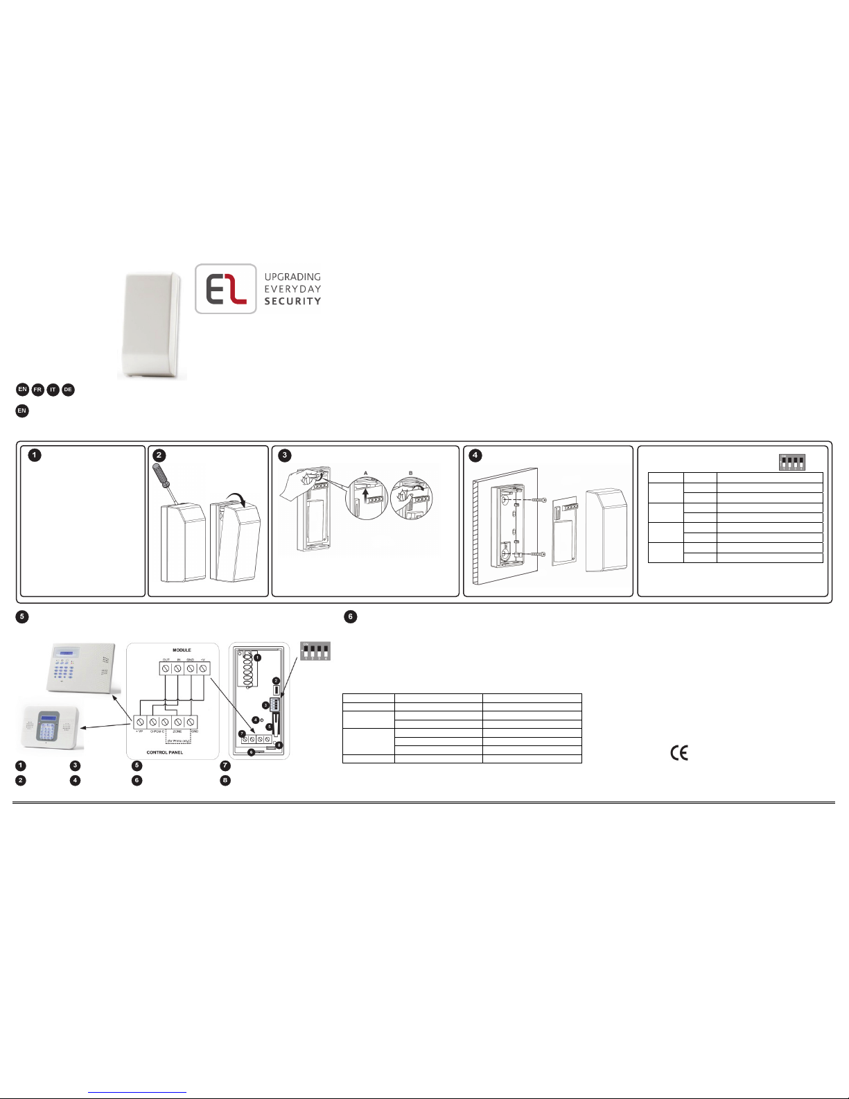
DIP Switch Settings (default *)
Switch State Description
1 ON Tamper on
OFF * Tamper off
2 ON Low battery on
OFF * Low battery off
3 ON Communication trouble on
OFF * Communication trouble off
4 ON For Prime
OFF * For CommPact
NOTE: If switches (1-3) are set to ON the output of the
module will trigger the wired zone on the panel and
create an alarm according to the panel's configurati on.
Terminal Wiring and PCB Layout
Antenna
Test Button
Dip Switch
LED Indicator
Tamper Switch
Wiring Knockout
Terminal Block
PCB Release Tab
Registering and Testing the 2-Way Siren
Power-up the module. Once the Red and Green LEDs are flashing
consecutively, send a signal from the siren by inserting the batteries. If the LED
continues flashing Red and Green, press the tamper on the siren.. Once
registered, press the Test button. The Green LED begins to flash according to
the transmission quality (4 flashes – best, 1 flash – poor). Close the module
housing cover to complete registration.
LED Display
LED State Description
Yellow On Siren Low battery
Green On Normal Operation
Flashing Testing mode
Red On Communication tro uble
Flashing Siren tamper activated
Intermittent flashing Module tamper activated
Red & Green Flashing (consecutively) Registration/ deletion mode
NOTE: A combination of troubles is indicate d by a 3 second steady Red
LED followed by a 3 second blinkin g Yellow LED.
Deleting a Siren
Open the 2-Way Siren Module and press the Test button for
approximately 7 seconds until the Red and Green LEDs flash
consecutively. This confirms the deletion.
Technical Specifications
Frequency – 868 MHz, 433 MHz, Power – 12VDC
Operating Temperature – -10 – 55°C
All rights reserved.
No part of this document may be reproduced in any form without prior
written permission from the publisher
Electronics Line 3000 Ltd. 11/2014 5IN2138 D

Introduction
Le Module bidirectionnel EL-4262 est un module complémentaire qui est utilisé pour coupler la
gamme des Sirènes Electronics Line (EL4726 et EL4723) avec les centrales CommPact et Infinite
Prime.
Paramètres de la centrale
Pour la Commpact ( à partir de la version 401.37 et supérieure):
1. En entrée-Régler la sortie PGM en Sirène
2. En sortie-Régler la zone 33 en ( NF )
Pour l’Iinfinite Prime - En entrée-Régler la sortie PGM en Sirène
, , (reportez-vous à ).
NOTE: pour une meilleure performance du produit, il est recommandé d'installer le module en dehors de la centrale.
Câblage terminal et Coté Compos ants (reportez-vou s à )
Antenne
Bouton Test
Commutateurs
Indicateur LED
Autoprotection
Passage de Câble
Bornier Câblage
Circuit
Réglage des commutateurs (par default *)
Switch Etat Description
1 ON Autoprotection Active
OFF * Autoprotection Inactive
2 ON Batterie basse Active
OFF * Betterie basse Inactive
3 ON Trouble communication Active
OFF * Trouble communicatio n Inactive
4 ON Pour Infinite Prime
OFF* Pour Commpact
NOTE: Si les commutateurs (1-3) sont réglés sur ON la sortie du module va déclencher la zone filaire de la centrale et de créer une
alarme en fonction de la configuration de la centrale.
Enregistrement et Test de la Sirène Bidirectionn elle
Mettez sous tension. Une fois que les LEDs rouge et verte clignotent consécutivement, envoyer un signal
de la sirène en insérant les batteries. Si la LED continue à clignoter en rouge et vert, appuyez sur l’
autoprotection de la sirène. Une fois enregistré, appuyez sur le bouton de test. La LED verte clignote selon
la force de signal (4 clignotements - excellent, 1 clignotement faible). Fermez le couvercle pour terminer
l'enregistrement.
Affichage LED
LED Etat Description
Jaune On Batterie Faible
Vert
On Mode Normal
Clignotant Mode Test
Rouge
On Touble communication
Clignotant Autoprotection Sirène
Clignotant
par-intermittance
Autoprotection Module
Rouge &
Vert
ClignotantContinu
Enregistrement /
Effacement
NOTE: Une combinaison de Défaut est indiquée par l’allumage de la LED en rouge
fixe pendant 3s suivie de la LED jaune clignotant pendant 3s.
Suppression d'une sirène
Ouvrez le module Sirène et appuyez sur le bouton de test pendant
environ 7 secondes jusqu'à ce que la LED rouge et verte clignotent
consécutivement. Ceci confirme la suppression.
Technical Specificati ons - Frequence – 868 MHz, 433 MHz, Power
– 12VDC, Temperature de fonctionnement -10 – 55°C
Introduzione
Il Modulo Per Sirena Radio Bidirezionale EL-4262 è un modulo aggiuntivo il cui scopo è
consentire di utilizzare la sirena radio bidirezionale EL4726 con la centrale CommPact
monodirezionale.
Programmazione della centrale
Utilizzabile dalla versione 401.37 e successive della centrale CommPact:
1. Programmazione PGM – Programmare il Tipo di associazione della PGM come “SIRENA
ESTERNA”.
2. Programmazione Zona – Programmare il LOOP della Zona 33 come “N.C.
, , (fare riferimento a ).
NOTA: Per ottenere prestazioni migliori è consigliabile installare il modulo esternamente alla centrale.
Cablaggio Terminal e Sch eda elettronica (fare riferim ento a )
Antenna
Pulsante di test
Microinterruttori
LED
Tamper
Ingresso cavo
Morsettiera
Blocco scheda elettronica
Impostazione dei microinterruttori (d efault *)
Microinterruttore Posizione Descrizione
1 ON Tamper attivo
OFF * Tamper non attivo
2 ON Basso livello batterie attivo
OFF * Basso livello batterie non attivo
3 ON Anomalia di comunicazione attivo
OFF * Anomalia di comunicazione non attivo
4 ON Per utilizzo con centrali Prime
OFF * Per utilizzo con centrali CommPact
NOTA: Se i microinterruttori 1-3 sono impostati su ON l’uscita del modulo, al presentarsi delle anomalie, attiverà la zona cablata della
centrale generando allarme contestualmente a come la zona è stata programmata.
Memorizzazione e Test del Mo dulo per Sirena Radio Bidire zionale
Alimentare il modulo. Quando il LED lampeggia ciclicamente di colore Rosso e Verde inviare un segnale
dalla sirena radio alimentandola. Se il LED continua a lampeggiare premere il tamper a bordo della sirena
per trasmettere nuovamente il segnale. Completata la registrazione premere il pulsante di Test, il LED
lampeggierà di colore Verde indicando la qualità della trasmissione (4 lampeggi – ottimo, 1 lampeggio –
scarso). Chiudere il modulo per completare la registrazione.
LED Display
LED Stato Descrizione
Giallo Acceso Basso livello batteria
Verde
Acceso Modo operativo normale
Lampeggiante Modalità Test
Rosso
Acceso Anomalia comunicazione
Lampeggiante Tamper sirena aperto
Lampeggio intermittente Tamper modulo aperto
Rosso &
Verde
Lampeggio
(Consecutivamente)
Modalità
registrazione/cancellazione
NOTA: Più anomalie presenti contemporaneamente vengono indicate tramite
l’accensione per 3 secondi del LED Rosso seguito dal lampeggio intermittente del
LED Giallo per 3 secondi.
Cancellazione della sirena
Aprire il Modulo Per Sirena Radio Bidirezionale e premere il
pulsante di Test per circa 7 secondi fino a che il LED lampeggerà
consecutivamente di colore Rosso e Verde. Questa indicazione
conferma la cancellazione della sirena.
Specifiche Tecniche - Frequenza– 868 MHz, 433 MHz,
Alimentazione – 12Vcc, Temperatura di funzioname nto – da -10°C a
55°C
Einführung
Das 2-Weg Sirenenmodul EL-4262 ist ein Zusatzmodul, das genutzt wird, um die Reihe der 2-Weg
Sirenen von Electronics Line (EL4726 und EL4723) mit den Steuertafeln von CommPact und Prime
1-Weg zu paaren.
Einstellungen der Steuertafel
Für die Tafel von CommPact (ab Version 401.37 und höher):
1. Eingabe-Event – Stellen Sie die PGM Ausgabe als ‘SIREN MODULE’ ein.
2. Ausgabe-Event – Stellen Sie die Zone #33 ‘LOOP TYPE’ als Normalerweise geschlossen ein.
Für Prime Panel - Eingabe-Event – Stellen Sie die PGM Ausgabe als ‘SIREN’ ein.
, , (gelten für ).
ANMERKUNG: Für eine maximale Leistung des Produktes wird empfohlen, das Modul außerhalb der Steuertafel zu
montieren
Klemmenbelegung und PCB Anordnung (gelten für )
Antenne
Testknopf
Dip-Switch
LED Indikator
Sabotagekontakt
Kabeldurchführung
Klemmleiste
PCB Entriegelungslasche
Einstellungen des DIP-Schal ters (Standardeinstellung *)
Schalter Status Beschreibung
1
ON Sabotagekontakt an
OFF * Sabotagekontakt aus
2
ON Niedriger Ladestand der Batterie an
OFF * Niedriger Ladestand der Batterie aus
3
ON Kommunikationsproblem an
OFF * Kommunikationsproblem aus
4
ON Für Prime
OFF * Für CommPact
ANMERKUNG: Wenn die Schalter (1-3) auf ON gestellt sind, wird die Ausgabe des Moduls die verdrahtete Zone auf der Steuertafel
auslösen und im Einklang mit der Konfiguration der Tafel einen Alarm einleiten
Registrierung und Testen der 2-Weg Sirene
Schalten Sie das Modul ein. Sobald die LED-Leuchte hintereinander rot und grün aufleuchtet, senden Sie
durch das Einlegen der Batterien ein Signal von der Sirene. Wenn die LED-Leuchte auch weiterhin
abwechselnd rot und grün aufleuchtet, drücken Sie auf den Sabotagekontakt an der Sirene. Nach der
Registrierung drücken Sie auf den Testknopf. Die grüne LED Leuchte beginnt im Einklang mit der
Übertragungsqualität aufzuleuchten (4 Mal Blinken – am besten, 1 Mal blinken – schlechte Qualität).
Schließen Sie das Gehäuse des Moduls, um die Registrierung abzuschließen.
LED Display
LED Status Beschreibung
Gelb An
Niedriger Ladestand der Batterie der
Sirene
Grün
An Normaler Betrieb
Blinkt Testmodus
Rot
An Störung der Kommunikation
Blinkt
Der Sabotagekontakt der Sirene ist
aktiviert
Intermittierendes
Blinken
Der Sabotagekontakt des Moduls ist
aktiviert
Rot&
Grün
Blinkt
(hintereinander)
Modus der Registrierung / Lösch ung
ANMERKUNG: Eine Kombination von Problemen wird durch 3 Sekunden
dauerhaft rot angezeigt LED bei einer 3 Sekunden blinkende gelbe LED gefolgt.
Das Löschen einer Sirene
Öffnen Sie das Modul der 2-Weg Sirene, und drücken Sie etwa 7
Sekunden lang auf den Testknopf, bis die roten und grünen LEDLeuchten hintereinander aufblinken. Dies bestätigt die Löschung.
Technische Spezifikat ionen - Frequenz – 868 MHz, 433 MHz,
Stromzufuhr – 12V, Gleichstrom, Betriebstemperatur – -10 – 55°C
 Loading...