

2
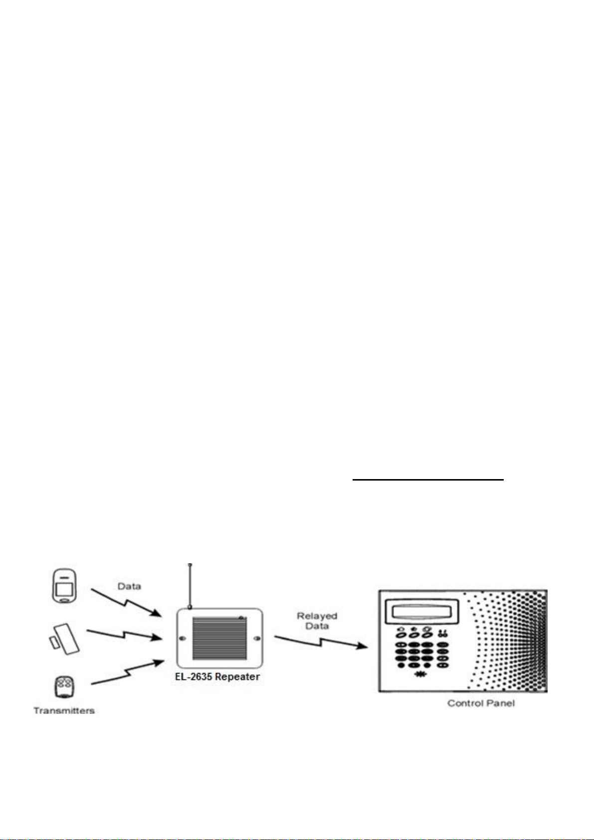
Figure 1: Typical Single Repeater
EL-2635 & EL2635P Repeater & Programming keypad – Repeater & Programierbedienteil – Repeteur & Clavier – Repeater & Keypad
Conrad No: 1276483 & 1276484
SAFETY WARNINGS
•
To prevent short circuits, this product should only be used inside and only in dry
spaces. Do not expose the components to rain or moisture. Do not use the product
close to a bath, swimming pool etc.
•
Do not expose the components of your systems to extremely high temperatures
or bright light sources.
•
In case of improper usage or if you have altered and repaired the product
yourself, all guarantees expire. Electronics Line does not accept responsibility in
the case of improper usage of the product or when the product is used for
purposes other than specified. Electronics Line does not accept responsibility for
additional damage other than covered by the legal product responsibility.
•
This product is not a toy. Keep out of reach of children.
•
The product should only be repaired or serviced by a qualified repairman.
•
Keep batteries out of the reach of children. Dispose of batteries as chemical
waste. Never use old and new batteries or different types of batteries together.
Remove the batteries when you are not using the system for a longer period of
time. Check the polarity (+/-) of the batteries when inserting them in the product.
Wrong positioning can cause an explosion.
•
Only connect the adapter to the mains after checking whether the mains voltage
is the same as the values on the identification tags. Never connect an adapter
when it is damaged. In that case, contact your supplier.
INTRODUCTION
The EL-2635 wireless repeater is a part of the Electronics Line Secuplace series,
and operates together with the Secuplace alarm system. When you wish to
know more about the complete system, its possibilities and its settings, then
you can check out the installation manual or visit www.electronics-line.com. Up to
four repeaters can be registered to the control panel with 32 transmitters
registered to each repeater. The repeater is powered by either 9VAC or
12VDC with a 6V rechargeable backup battery pack. Registration and
maintenance tests are performed using a plug-in LCD Programming Keypad
(EL2635-P) that provides a comprehensive interface to the repeater.
3
EL-2635 Repeater & Programming keypad – Repeater & Programierbedienteil – Repeteur & Clavier – Repeater & Keypad
Conrad No: 1276483 & 1276484
INSTALLATION
1.
Register all wireless devices to the Secuplace control panel as explained in
the Secuplace installation manual.
2.
On the control panel, define the detection devices that are intended to transmit
via the repeater as follows:
From the Programming menu, select Devices, Zones [911].
Select the zone you want to program (1-32).
From the zone’s sub-menu, select Repeater [#9].
Select “Use Repeater”.
Note: It is not necessary to define, at the control panel, the keypads and
keyfobs that are registered to the repeater.
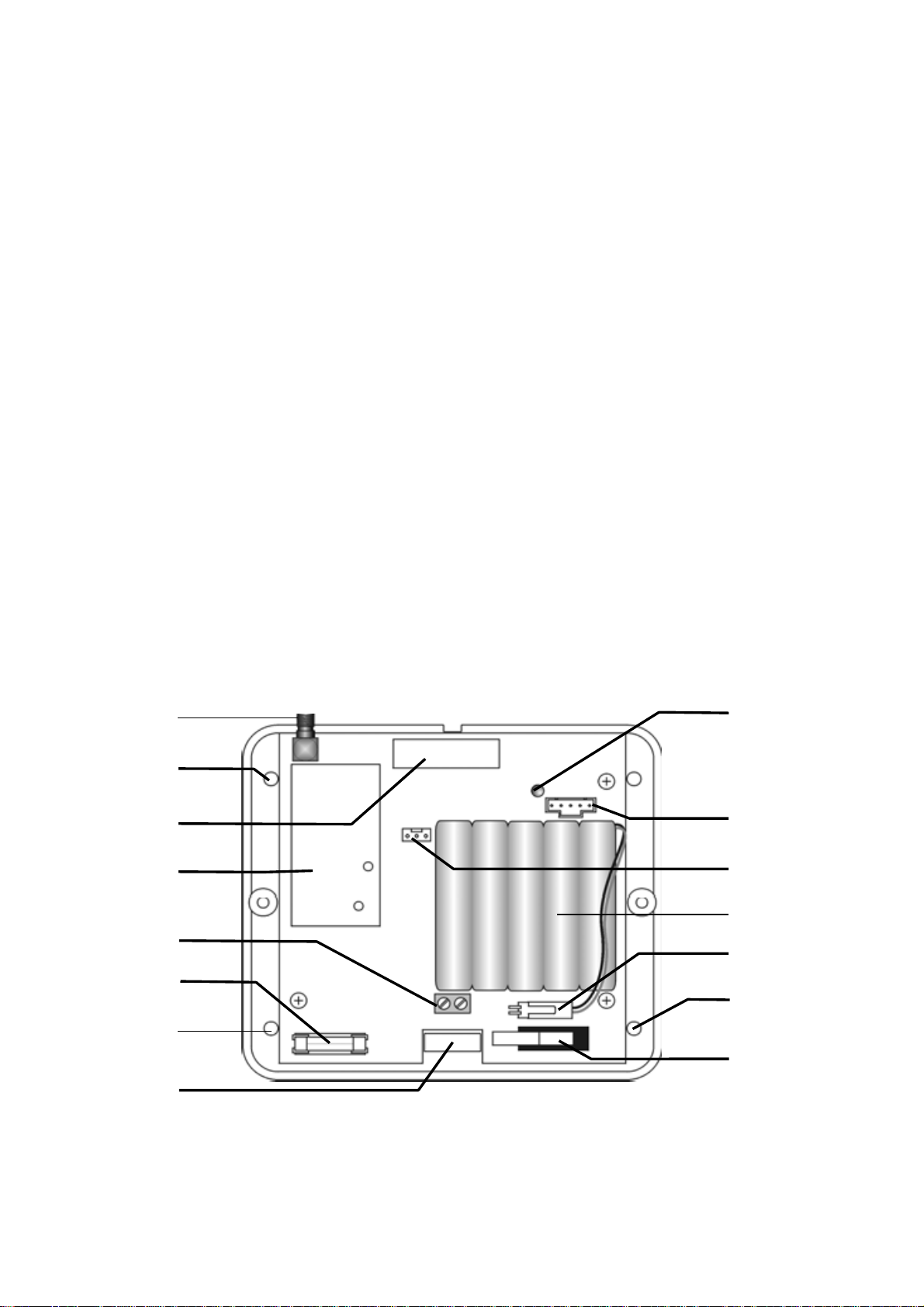
3.
Open the EL-2635’s plastic housing. To do so, remove the two cover
screws and lift the front cover away from the base.
Antenna
Connector
Upper
Mounting
Hole
Transmitter
Receiver
Power Input
Terminals
AC Power
Protection Fuse
Lower
Mounting
Hole
Wiring
Hole
Figure 2: EL-2635 (cover
removed)
LED Indicator
Flash
Programming
Programming
Keypad (EL2635P)
Backup
Battery Pack
Battery Connector
Lower
Mounting
Hole
Tamper
Switch

4
EL-2635 Repeater & Programming keypad – Repeater & Programierbedienteil – Repeteur & Clavier – Repeater & Keypad
Conrad No: 1276483 & 1276484
4.
Connect the antenna provided to the antenna connector.
5.
Connect the backup battery pack to the Battery connector.
6.
Connect a 9VAC or 12VDC transformer to the Power Input terminal block
(polarity is not important).
7.
All registration and test functions, described in the following sections, are
performed from the LCD Programming Keypad (EL2635-P) shown in Figure

4
EL-2635 Repeater & Programming keypad – Repeater & Programierbedienteil – Repeteur & Clavier – Repeater & Keypad
Conrad No: 1276483 & 1276484
LED Indication
Description
Steady Green
AC & Battery OK
Flashing Red
AC Loss
Flashing Orange
Low Battery
LED Indication
Description
Flashing Green
Signal Reception
Flashing Red
Signal Transmission
Connect the Programming Keypad (EL2635-P) to the Programming
Keypad (EL2635-P) connector.
Note: The Programming Keypad (EL2635-P) is not able to operate on
battery power only.
8.
Test the repeater from the required mounting location before permanently
mounting the unit.
9.
Mount the base to the wall using four screws and replace the front cover.
When the tamper switch is open, the bicolor LED provides indication regarding
repeater transmission and reception as
an aid during the installation procedure
–
see Table 1. When the tamper switch
is closed, the bi-color LED provides
indication regarding power status – see
Table 1: LED Indication (Tamper Open)
Table 2.
Table 2: LED Indication (Tamper Closed)
REGISTERING THE REPEATER TO
THE CONTROL PANEL
For the control panel to recognize the repeater, you
must register the repeater to the control panel.
To register the repeater to the control panel:
1.
Set the control panel to Registration mode
as follows:
From the Programming menu, select
Devices, Repeaters [914].
Select the repeater you want to register
(1-4).
From the repeater’s sub-menu, select
Register [#1].
2.
Send two Status transmissions from
repeater as follows:
On the Programming Keypad (EL2635-P),
press ... until 5. STS Transmit appears on
the display.
Press ./.
Press ./ again.
the
Figure 3: LCD rogramming
Keypad (EL2635-P)

5
EL-2635 Repeater & Programming keypad – Repeater & Programierbedienteil – Repeteur & Clavier – Repeater & Keypad
Conrad No: 1276483 & 1276484
3.
Confirm registration to the control panel as follows:
When Save? appears on the control panel’s LCD display,
press ./.
REGISTERING TRANSMITTERS TO THE REPEATER
You can register up to 32 transmitters to the EL-2635
repeater.
Note: Do not register the same transmitter to more
than one repeater.
To register transmitters to the repeater:
1.
On the LCD Programming Keypad (EL2635-P),
press
... until 4. TX Register appears on the display.
2.
3.
4.
Press ./;
Press
display.
New Device
./
again;
Transmit 1
appears on the display.
appears on the
Send two transmissions from the device you want
to register.
Figure 4: Transmitter
Registration Procedure
5.
When the transmitter number and Save? appear
on the display, press
./
to confirm registration.
Note: The EL-2635 repeater automatically allocates a transmitter
number to each newly registered device. Write this number and the zone
number on the sticker provided with the sensor and stick it inside
the transmitter’s cover for future reference.
6.
After you have confirmed registration, the display returns to New Device.
Press
./
to register another device or .x to exit Registration mode.
DELETING REGISTERED TRANSMITTERS
To delete transmitters from the repeater’s register:
1.
On the LCD Programming Keypad (EL2635-P),
press
... until 3. TX Delete appears on the display.
2.
Press ./; the first transmitter in the list appears on
the display.
3.
Use the arrow navigation keys (.../...) to scroll to
the transmitter you want to delete.
6.
Select another
transmitter to
delete or press .x to
exit.
4.
5.
Press
Press
./
./
deleted.
to select the transmitter.
again for confirmation; the transmitter is

6
EL-2635 Repeater & Programming keypad – Repeater & Programierbedienteil – Repeteur & Clavier – Repeater & Keypad
Conrad No: 1276483 & 1276484
Figure 5: Delete Transmitter Procedure

7
EL-2635 Repeater & Programming keypad – Repeater & Programierbedienteil – Repeteur & Clavier – Repeater & Keypad
Conrad No: 1276483 & 1276484
INSTALLER UTILITIES
The EL-2635 repeater offers two installer utilities that serve as a valuable aid
during installation and maintenance.
TX List
The TX List is a scrollable inventory of all registered transmitters and their last
reported signal strength.
To view the TX list:
1.
Press ... until 1. TX List appears on the
display.
2.
Press ./; the first transmitter in the list is
displayed.
3.
4.
Use the arrow navigation keys (.../...) to
scroll through the list.
Press .x to exit the list.
Figure 6: TX List Procedure
TX Test
TX Test is a utility that enables you to identify registered transmitters and test their
signal strength.
To perform a TX test:
1.
Press ... until 2. TX Test appears on the
display.
2.
Press ./.
3.
Activate a transmitter; the transmitter number,
type and signal strength are displayed.
4.
Press .x to exit TX Test mode.
Figure 7: TX Test Procedure

8
EL-2635 Repeater & Programming keypad – Repeater & Programierbedienteil – Repeteur & Clavier – Repeater & Keypad
Conrad No: 1276483 & 1276484
TECHNICAL DATA
EL-2635
Frequency:
Antenna:
868.35MHz FM
External Whip
Operating Voltage: 9VAC or 12VDC
Backup Battery: 6V/850mAh
(5 x 1.2V Ni-MH rechargeable cells, size AAAL)
Current Consumption: 100mA max. (during transmission)
Number of Transmitters: 32 max.
Tamper Protection: Front Cover (N.C.)
Operating Temperature: 0-60°C
Dimensions:
123 x 109 x 27mm
EL2635-P
Programming cable length: 50 cm
Operating Temperature: 0-60°C
Dimensions:
135 x 130 x 34 mm
International Headquarters:
Electronics Line 3000 Ltd.
14 Hachoma St., 75655
Rishon Le Zion, Israel
Tel: (+972-3) 963-7777
Fax: (+972-3) 961-6584
All data is subject to change without prior notice techniques In no event shall Electronics Line be liable for an amount in excess of EL3K’s original selling price of this product, for any loss or
damage whether direct, indirect, incidental, consequential or otherwise arising out of any failure of the product.
Hereby, Electronics Line declares that this sensor/transmitter is in compliance with the essential requirements and other relevant provisions of Directive 1999/5/EC.
Alle Daten können jederzeit ohne vorherige Ankündigung geändert werden. In keinem Fall haftet Electronics Line für einen Betrag von mehr als des ursprünglichen Kaufpreis des Produkts,
für Verluste oder Schäden, ob direkte, indirekte, zufällige, Folge- oder die aus einer Fehlfunktion des Produkts entstandenen. Hiermit erklärt Electronics Line, dass sich dieses Gerät in
Übereinstimmung mit den grundlegenden Anforderungen und den anderen relevanten Vorschriften der Richtlinie 1999/5/EG befindet. Hierbij verklaart Electronics Line dat het toestel dit
apparaat in overeenstemming is met de essentiële eisen en de andere relevante bepalingen van richtlijn 1999/5/EG. Vollständige CE Erklärung unter www.secplan.de/ce
Ces spécifications techniques sont sujettes à modifications sans avis préalable. Electronics Line (E.L) n'est en aucun cas responsable de l'augmentation du prix de vente du produit, de toute
perte ou dommage direct, indirect, accidentel, consécutif ou provenant d'un défaut du produit. Par la présente Electronics Line déclare que l'appareil ce dispositif est conforme aux
exigences essentielles et aux autres dispositions pertinentes de la directive 1999/5/CE
Specificaties kunnen wijzigen zonder voorafgaande melding hiervan. Hierbij verklaart Electronics Line dat het toestel dit apparaat in overeenstemming is met de essentiële eisen en
de andere relevante bepalingen van richtlijn 1999/5/EG.
06/2011 5IN1561
 Loading...