

Electronics International Inc MVP-50T Operating Instructions Manual


Important Notice
***** MUST READ *****
Page 1 of 4
If you think it is not important to read this manual, you’re wrong! This manual
contains important operating information that may affect the safety of you, your
aircraft and passengers.
Read the Warranty / AgreementRead the Warranty / Agreement
Read the Warranty / Agreement. There is information in the Warranty/Agreement that may alter your
Read the Warranty / AgreementRead the Warranty / Agreement
If you do not accept the terms of the Warranty / Agreement, doIf you do not accept the terms of the Warranty / Agreement, do
decision to install this product.
not install this productnot install this product
not install this product. This product may be returned for a refund. Contact Electronics International
not install this productnot install this product
inc. for details.
If you do not accept the terms of the Warranty / Agreement, do
If you do not accept the terms of the Warranty / Agreement, doIf you do not accept the terms of the Warranty / Agreement, do
If you do not agree to and accept If you do not agree to and accept
If you do not agree to and accept
If you do not agree to and accept If you do not agree to and accept
ProductProduct
Product
ProductProduct
By installing this product, the aircraft owner/pilot and installer agree to hold Electronics International Inc.
harmless and in no way responsible for monetary compensation, including punitive damages for any
incident, harm and/or damage associated with this product. If you do not agree to the above,
INSTALL THIS PRODUCT.INSTALL THIS PRODUCT.
INSTALL THIS PRODUCT. This product may be returned for a refund. Contact Electronics Interna-
INSTALL THIS PRODUCT.INSTALL THIS PRODUCT.
tional inc. for details.
The pilot
allow anyone to operate the aircraft that does not know how to properly interpret and operate this product.
Keep the Operating Manual in the aircraft at all times. If you do not thoroughly understand the operation
of this product, contact a knowledgeable flight instructor for training.
The ability for this product to respond to an engine or aircraft system anomaly is directly related to how
that anomaly affects the reading of the function(s) being monitored (i.e.: if an engine fire does not affect
the ITT or Oil Temp then the ITT and Oil Temp readings will not change).
This instrument only displays the parameters for the function(s) being monitored. The pilot is responsible
for interpreting the data and determining if an engine or aircraft system anomaly exists. When using this
instrument, the pilot’s diagnostic ability is limited to his/her interpretation of the displayed data and the
their observation skills. To improve these skills the pilot should seek training from a flight instructor.
. .
. You may return the product for a refund. Contact Electronics International Inc. for details.
. .
must must
must understand the operation and limitations of this product before flying the aircraft. Do not
must must
ALLALL
the terms of this warranty, the terms of this warranty,
ALL
the terms of this warranty,
ALLALL
the terms of this warranty, the terms of this warranty,
DO NOT Install ThisDO NOT Install This
DO NOT Install This
DO NOT Install ThisDO NOT Install This
DO NOTDO NOT
DO NOT
DO NOTDO NOT
If after reading this manual you do not have the knowledge to interpret the displayed data to operate the
aircraft safely or to detect engine and/or aircraft system problems, contact a knowledgeable instructor for
training prior to flying the aircraft with this instrument.
If you detect a problem using this instrument, it is your responsibility to take appropriate action to insure
the safety of the flight. Practice simulating problems to build your skills and to improve your understand
of the relationships between problems and their affects on the displayed data. To insure you are taking
appropriate action, contact a knowledgeable flight instructor for training. Inappropriate action can lead to
aircraft and/or engine damage, personal injury or death.

Important Notice
***** MUST READ *****
Page 2 of 4
This manual does not make any recommendations as to specific operating parameters or controlling
methods. Check the airframe and/or engine manufacturer’s recommendations to properly operate the
aircraft systems and engine. It is the pilot’s responsibility to operate the engine and aircraft safely.
It is possible for any instrument to fail thereby displaying inaccurate high, low or jumpy readings.
Therefore, you
your aircraft safely in spite of an instrument failure. If you do not have this knowledge, contact the
FAA or a knowledgeable flight instructor for training prior to flying the aircraft with this instrument.
Electronics International Inc. is not liable or responsible for a pilot’s action or any situation that results
in personal injury, property damage, missed commitments, lack of use of an aircraft or any expenses
incurred due to: product failure, inaccuracy in displayed data or text files, display or display format
issues, software bugs or problems, upgrade or customization issues, misinterpretation of the display,
warning and/or limit settings, calibration problems, installation issues (leaks, mis-wiring, obstructions,
damage to aircraft or components, incorrect installation of any parts, wrong parts, parts that don’t fit,
etc.) or any other issues related to the installation or operation of this product. All of the above are
solely the pilot’s and/or installer’s responsibility. The pilot
product before flying the aircraft. The pilot will not allow anyone to operate the aircraft that does not
know the operation of this product. The pilot will keep the instrument Operating Instructions in the
aircraft at all times.
mustmust
must be able to recognize an instrument failure and you
mustmust
must must
must understand the operation of this
must must
mustmust
must be proficient in operating
mustmust
Set a unique password to protect all of the calibration and setup data in the MVP-50 (MVP). If setup or
calibration data is inadvertently or improperly changed, you could get inaccurate readings that may lead
to improper operation of the aircraft or engine. This could result in engine damage and/or an emergency situation.
Before using the Weight and Balance screen check that the “Weight and Balance Setup” data in the
MVP System Configuration Menu is accurate. Always verify the MVP weight and balance data with
you aircraft’s POH.
Before flying the aircraft verify that the instrument markings displayed on the MVP are accurate with
your POH for every function displayed on the MVP.
Verify that the horsepower displayed on the MVP is accurate with your aircraft's POH and/or engine TC
data.
The MVP allows the pilot to enter checklists, flight plans and general information through the USB port.
This data must be verified for accuracy by the pilot prior to flight.
The MVP must be calibrated to the aircraft fuel system and the MVP's accuracy must be verified before
flying the aircraft.

Important Notice
***** MUST READ *****
Fuel Level Accuracy Limitations:Fuel Level Accuracy Limitations:
Fuel Level Accuracy Limitations:
Fuel Level Accuracy Limitations:Fuel Level Accuracy Limitations:
Page 3 of 4
The accuracy limitations of the MVP are listed below.
anyone flying the aircraft aware of these limitations.anyone flying the aircraft aware of these limitations.
anyone flying the aircraft aware of these limitations.
anyone flying the aircraft aware of these limitations.anyone flying the aircraft aware of these limitations.
1. Angle of Attack -1. Angle of Attack -
1. Angle of Attack - The MVP must be calibrated with the aircraft in a cruise angle of attack. If
1. Angle of Attack -1. Angle of Attack the aircraft is in an angle of attack other than cruise, the MVP may display inaccurate fuel levels
(depending on the mounting location and type of sensor used). If your aircraft does not sit at a cruise
angle of attack when on the ground, it may not display accurate fuel levels.
different angles of attack to determine how the MVP fuel level readings are affected.different angles of attack to determine how the MVP fuel level readings are affected.
different angles of attack to determine how the MVP fuel level readings are affected.
different angles of attack to determine how the MVP fuel level readings are affected.different angles of attack to determine how the MVP fuel level readings are affected.
Full Fuel Readings -Full Fuel Readings -
2.
Full Fuel Readings - As a tank is filled the fuel sensor may be unable to detect the fuel entering
Full Fuel Readings -Full Fuel Readings the upper corners of the fuel tank. If this is the case with your sensor, the MVP may display fuel levels
lower than the actual fuel in the tanks when the tanks are full. When the fuel level drops to a point
where the fuel sensor starts to detect a change, the displayed fuel level should be accurate.
accuracy of your system by comparing the displayed fuel levels on the MVP to the fuelaccuracy of your system by comparing the displayed fuel levels on the MVP to the fuel
accuracy of your system by comparing the displayed fuel levels on the MVP to the fuel
accuracy of your system by comparing the displayed fuel levels on the MVP to the fuelaccuracy of your system by comparing the displayed fuel levels on the MVP to the fuel
levels listed in the flight manual at each fill up.levels listed in the flight manual at each fill up.
levels listed in the flight manual at each fill up.
levels listed in the flight manual at each fill up.levels listed in the flight manual at each fill up.
3. Low Fuel Readings -3. Low Fuel Readings -
3. Low Fuel Readings -
3. Low Fuel Readings -3. Low Fuel Readings for an indicated tank level below 1/8for an indicated tank level below 1/8
for an indicated tank level below 1/8. You should always fly the aircraft in such a manner as to
for an indicated tank level below 1/8for an indicated tank level below 1/8
at least maintain the FAA minimum fuel requirements in the aircraft at all times.
mounting location and type of fuel sensor used, the MVP may not be able to accuratelymounting location and type of fuel sensor used, the MVP may not be able to accurately
mounting location and type of fuel sensor used, the MVP may not be able to accurately
mounting location and type of fuel sensor used, the MVP may not be able to accuratelymounting location and type of fuel sensor used, the MVP may not be able to accurately
measure the last few gallons of fuel in the tanks.measure the last few gallons of fuel in the tanks.
measure the last few gallons of fuel in the tanks.
measure the last few gallons of fuel in the tanks.measure the last few gallons of fuel in the tanks.
Do not rely on the MVP to determine the fuel level in the tankDo not rely on the MVP to determine the fuel level in the tank
Do not rely on the MVP to determine the fuel level in the tank
Do not rely on the MVP to determine the fuel level in the tankDo not rely on the MVP to determine the fuel level in the tank
It is the pilot/owner’s obligation to makeIt is the pilot/owner’s obligation to make
It is the pilot/owner’s obligation to make
It is the pilot/owner’s obligation to makeIt is the pilot/owner’s obligation to make
Test your aircraft atTest your aircraft at
Test your aircraft at
Test your aircraft atTest your aircraft at
Check the Check the
Check the
Check the Check the
Depending on theDepending on the
Depending on the
Depending on theDepending on the
4. Improper Calibration -4. Improper Calibration -
4. Improper Calibration - If the MVP has not been properly calibrated it will not display accurate
4. Improper Calibration -4. Improper Calibration fuel levels in the tanks. It is important to verify the accuracy of the MVP.
your measured fuel levels in the tanks with the readings on the MVP before each flight.your measured fuel levels in the tanks with the readings on the MVP before each flight.
your measured fuel levels in the tanks with the readings on the MVP before each flight.
your measured fuel levels in the tanks with the readings on the MVP before each flight.your measured fuel levels in the tanks with the readings on the MVP before each flight.
5. Poor Connections -5. Poor Connections -
5. Poor Connections - Poor connections between the wires leading from the EDC to the fuel
5. Poor Connections -5. Poor Connections sensors can become intermittent with age. An intermittent connection most likely will show up as
wandering or inaccurate readings on the MVP.
in the tanks with the readings on the MVP before each flight.in the tanks with the readings on the MVP before each flight.
in the tanks with the readings on the MVP before each flight.
in the tanks with the readings on the MVP before each flight.in the tanks with the readings on the MVP before each flight.
6. Defective Fuel Level Sensors -6. Defective Fuel Level Sensors -
6. Defective Fuel Level Sensors - Fuel sensors can become intermittent or change resistance
6. Defective Fuel Level Sensors -6. Defective Fuel Level Sensors with age. It is not uncommon to find intermittent problems even in new sensors. An intermittent
problem with a fuel sensor most likely will show up as wandering or inaccurate readings on the MVP.
Always cross check the measured fuel levels in the tanks with the readings on the MVPAlways cross check the measured fuel levels in the tanks with the readings on the MVP
Always cross check the measured fuel levels in the tanks with the readings on the MVP
Always cross check the measured fuel levels in the tanks with the readings on the MVPAlways cross check the measured fuel levels in the tanks with the readings on the MVP
at each fill up.at each fill up.
at each fill up.
at each fill up.at each fill up.
If you ever find an inaccuracy issue or any other problem with a fuel level displayIf you ever find an inaccuracy issue or any other problem with a fuel level display
If you ever find an inaccuracy issue or any other problem with a fuel level display
If you ever find an inaccuracy issue or any other problem with a fuel level displayIf you ever find an inaccuracy issue or any other problem with a fuel level display
on the MVP, disable the fuel level display (see the “Redlines, Limits and Color Setup”on the MVP, disable the fuel level display (see the “Redlines, Limits and Color Setup”
on the MVP, disable the fuel level display (see the “Redlines, Limits and Color Setup”
on the MVP, disable the fuel level display (see the “Redlines, Limits and Color Setup”on the MVP, disable the fuel level display (see the “Redlines, Limits and Color Setup”
screen). This will alert anyone flying the aircraft to the condition of this display.screen). This will alert anyone flying the aircraft to the condition of this display.
screen). This will alert anyone flying the aircraft to the condition of this display.
screen). This will alert anyone flying the aircraft to the condition of this display.screen). This will alert anyone flying the aircraft to the condition of this display.
Always cross check your measured fuel levelsAlways cross check your measured fuel levels
Always cross check your measured fuel levels
Always cross check your measured fuel levelsAlways cross check your measured fuel levels
Always cross checkAlways cross check
Always cross check
Always cross checkAlways cross check

Important Notice
***** MUST READ *****
Page 4 of 4
Important Fuel Level Considerations:Important Fuel Level Considerations:
Important Fuel Level Considerations:
Important Fuel Level Considerations:Important Fuel Level Considerations:
DO NOT RELY SOLELY ON THE FUEL LEVEL DISPLAYED ON THE MVP TODO NOT RELY SOLELY ON THE FUEL LEVEL DISPLAYED ON THE MVP TO
DO NOT RELY SOLELY ON THE FUEL LEVEL DISPLAYED ON THE MVP TO
DO NOT RELY SOLELY ON THE FUEL LEVEL DISPLAYED ON THE MVP TODO NOT RELY SOLELY ON THE FUEL LEVEL DISPLAYED ON THE MVP TO
DETERMINE THE FUEL LEVELS IN THE AIRCRAFT.DETERMINE THE FUEL LEVELS IN THE AIRCRAFT.
DETERMINE THE FUEL LEVELS IN THE AIRCRAFT.
DETERMINE THE FUEL LEVELS IN THE AIRCRAFT.DETERMINE THE FUEL LEVELS IN THE AIRCRAFT.
eliminate or reduce the necessity for the pilot to use good flight planning, preflighteliminate or reduce the necessity for the pilot to use good flight planning, preflight
eliminate or reduce the necessity for the pilot to use good flight planning, preflight
eliminate or reduce the necessity for the pilot to use good flight planning, preflighteliminate or reduce the necessity for the pilot to use good flight planning, preflight
and in-flight techniques for managing fuel.and in-flight techniques for managing fuel.
and in-flight techniques for managing fuel. It is important the pilot adopt the practices listed
and in-flight techniques for managing fuel.and in-flight techniques for managing fuel.
below. If you are not familiar with these techniques, contact the FAA to acquire proper training.
1. 1.
A copy of this Operating Manual must be in the aircraft at all times.A copy of this Operating Manual must be in the aircraft at all times.
1.
A copy of this Operating Manual must be in the aircraft at all times.
1. 1.
A copy of this Operating Manual must be in the aircraft at all times.A copy of this Operating Manual must be in the aircraft at all times.
2. Flight Planning -2. Flight Planning -
2. Flight Planning - Always calculate the fuel requirement for each leg of a flight, including any
2. Flight Planning -2. Flight Planning alternate plans for bad weather. Keep this information available in the aircraft during the flight.
Keep a chart of the published fuel flows for various flight/engine conditions in the aircraft. Keep a
chart of the measured fuel flows for various flights in the aircraft. Measured fuel flows can be
considerably different from published figures.
The use of the MVP does not The use of the MVP does not
The use of the MVP does not
The use of the MVP does not The use of the MVP does not
3. Preflight - Do not rely on the MVP to determine the fuel level in the fuel tanks.3. Preflight - Do not rely on the MVP to determine the fuel level in the fuel tanks.
3. Preflight - Do not rely on the MVP to determine the fuel level in the fuel tanks.
3. Preflight - Do not rely on the MVP to determine the fuel level in the fuel tanks.3. Preflight - Do not rely on the MVP to determine the fuel level in the fuel tanks.
The pilot must visually check/measure the fuel levels in the tanks before every take-The pilot must visually check/measure the fuel levels in the tanks before every take-
The pilot must visually check/measure the fuel levels in the tanks before every take-
The pilot must visually check/measure the fuel levels in the tanks before every take-The pilot must visually check/measure the fuel levels in the tanks before every takeoff.off.
off. Cross check the measured fuel levels with the displayed levels on the MVP. Also, cross check
off.off.
these levels with the fuel requirements for the flight listed in your flight plan.
4. In Flight -4. In Flight -
4. In Flight - Make the MVP part of your normal instrument scan.
4. In Flight -4. In Flight displayed on the MVP with your flight plan at each leg of the flight or every 30 min-displayed on the MVP with your flight plan at each leg of the flight or every 30 min-
displayed on the MVP with your flight plan at each leg of the flight or every 30 min-
displayed on the MVP with your flight plan at each leg of the flight or every 30 min-displayed on the MVP with your flight plan at each leg of the flight or every 30 minutesutes
utes (if a leg is longer than 30 minutes). Calculate the fuel flows from the MVP displayed fuel
utesutes
levels and compare them with your charts of measured and published fuel flows for the aircraft. If
there is a discrepancy, land the aircraft at the nearest airport and verify the fuel levels. Discrepancies should be taken seriously.
5. New Pilot or Owner of the Aircraft -5. New Pilot or Owner of the Aircraft -
5. New Pilot or Owner of the Aircraft -
5. New Pilot or Owner of the Aircraft -5. New Pilot or Owner of the Aircraft aircraft, it is the previous aircraft pilot/owner’s responsibility to insure the new pilot/aircraft, it is the previous aircraft pilot/owner’s responsibility to insure the new pilot/
aircraft, it is the previous aircraft pilot/owner’s responsibility to insure the new pilot/
aircraft, it is the previous aircraft pilot/owner’s responsibility to insure the new pilot/aircraft, it is the previous aircraft pilot/owner’s responsibility to insure the new pilot/
owner has read this manual and is aware of any accuracy limitations and other impor-owner has read this manual and is aware of any accuracy limitations and other impor-
owner has read this manual and is aware of any accuracy limitations and other impor-
owner has read this manual and is aware of any accuracy limitations and other impor-owner has read this manual and is aware of any accuracy limitations and other important considerations. All limitations and operating characteristics learned from operat-tant considerations. All limitations and operating characteristics learned from operat-
tant considerations. All limitations and operating characteristics learned from operat-
tant considerations. All limitations and operating characteristics learned from operat-tant considerations. All limitations and operating characteristics learned from operating the MVP must be passed on to the new pilot/owner.ing the MVP must be passed on to the new pilot/owner.
ing the MVP must be passed on to the new pilot/owner.
ing the MVP must be passed on to the new pilot/owner.ing the MVP must be passed on to the new pilot/owner.
If there is a new pilot or new owner of theIf there is a new pilot or new owner of the
If there is a new pilot or new owner of the
If there is a new pilot or new owner of theIf there is a new pilot or new owner of the
Crosscheck the fuel levelsCrosscheck the fuel levels
Crosscheck the fuel levels
Crosscheck the fuel levelsCrosscheck the fuel levels

Contents
(Page 1 of 2)
Warranty/Agreement----------------------------------------------------------------------------------------- 1
1.0 Introduction: -------------------------------------------------------------------------------------------- 3
1.1 Features: ------------------------------------------------------------------------------- 4
1.2 Overview of the MVP Screens: --------------------------------------------------------- 4
1.3 System Hardware: ---------------------------------------------------------------------- 5
1.4 SELECT Knob and Button Operation: -------------------------------------------------- 6
1.5 Display Dimming: ----------------------------------------------------------------------- 7
1.6 Cleaning the Screen: -------------------------------------------------------------------- 7
2.0 Main Engine Screen: -------------------------------------------------------------------------- 8
2.1 Power-up Add Fuel Message: ---------------------------------------------------------- 10
2.2 Main Screen Layout: --------------------------------------------------------------------- 10
2.3 Arc Gauges: ----------------------------------------------------------------------------- 11
2.4 Vertical Strip Gauges: ------------------------------------------------------------------- 11
2.5 Annunciators (CAS): ------------------------------------------------------------------- 11
2.6 Digital Instruments: --------------------------------------------------------------------- 12
2.7 External Master Caution and Warning Lights: ------------------------------------------- 12
2.8 Voice Alarm Control Panel: ------------------------------------------------------------- 13
2.9 Disabling a Display: --------------------------------------------------------------------- 14
3.0 System Screen: ------------------------------------------------------------------------------- 16
3.1 Trim Indicator: -------------------------------------------------------------------------- 18
3.2 Flap Indicator: -------------------------------------------------------------------------- 18
3.3 Gear Position Indicator: ----------------------------------------------------------------- 18
3.4 Gear Up Warning: ---------------------------------------------------------------------- 19
3.5 Engine and System Functions: ---------------------------------------------------------- 19
3.6 Annunciators (CAS): ------------------------------------------------------------------- 19
3.7 Five Digital Instruments from the Main Screen: ------------------------------------------ 19
4.0 Flight Data Screens Menu: -------------------------------------------------------------------- 20
4.1 Help Screen: --------------------------------------------------------------------------- 22
4.2 System Screen: ------------------------------------------------------------------------- 22
4.3 Add Fuel Screen: ----------------------------------------------------------------------- 22
4.3.1 K Factor Adjustment Section: --------------------------------------------------- 22
4.3.2 Bottom Section: ----------------------------------------------------------------- 23
4.4 Fuel Management Screen: -------------------------------------------------------------- 24
4.4.1 Fuel Level Data: ----------------------------------------------------------------- 24
4.4.2 Fuel Flow Data: ----------------------------------------------------------------- 24
4.4.3 GPS Data: ----------------------------------------------------------------------- 24
4.4.4 Bottom Section: ----------------------------------------------------------------- 24
4.5 Timers Screen: ------------------------------------------------------------------------- 25
4.6 Clock and Hour Meters Screen: -------------------------------------------------------- 25
4.7 Weight and Balance Screen: ------------------------------------------------------------ 26
4.8 Checklist Screens: ---------------------------------------------------------------------- 26
4.9 Flight Notes Screens: ------------------------------------------------------------------- 27

4.10 Gen. Info. Screens: -------------------------------------------------------------------- 28
4.11 Data Logs Screens: -------------------------------------------------------------------- 29
5.0 Setup and Control Screens Menu: ------------------------------------------------------------ 30
5.1 USB and Data Recording Screen: ------------------------------------------------------ 32
5.1.1 Read Files From USB Data Stick Section: --------------------------------------- 32
5.1.2 Write Recorded Data to USB Section: ------------------------------------------ 32
5.1.3 Data Recording Setup Section: -------------------------------------------------- 33
5.2 Voice and Display Controls Screen: ---------------------------------------------------- 33
5.2.1 Voice Warning Control Section: ------------------------------------------------- 33
5.2.2 Test a Voice File Section: -------------------------------------------------------- 33
5.2.3 Display Controls Section: -------------------------------------------------------- 33
5.2.4 Button Controls Section: --------------------------------------------------------- 34
5.3 Screens Button Setup Screen: ---------------------------------------------------------- 34
5.4 System Configuration Screens Menu: --------------------------------------------------- 34
6.0 System Configuration Screens: ---------------------------------------------------------------- 36
6.1 Password Protection: ------------------------------------------------------------------ 38
6.1 Level #1 Password (Maintenance): ------------------------------------------------ 38
6.2 Level #2 Password (OEM): ------------------------------------------------------- 38
6.2 System Configuration Screens Overview: ----------------------------------------------- 39
6.3 USB Flight Data File Manager Screen: ------------------------------------------------- 39
6.4 USB Config and Software Program Manager Screen: ---------------------------------- 40
6.5 Change Password Screen: ------------------------------------------------------------- 41
6.6 Aircraft ID, Gear Warning and TAS Seup Screen: -------------------------------------- 42
6.7 Engine Data, Hour Meter, Flight Timer Setup Screen: ----------------------------------- 42
6.8 Serial Port Setup Screen: --------------------------------------------------------------- 43
6.9 Weight & Balance Setup Screen: ------------------------------------------------------- 45
6.10 Fuel Tank Calibration Screen: --------------------------------------------------------- 45
6.11 Pressure Altitude Calibration Screen: -------------------------------------------------- 46
6.12 Flaps, Trim and Special Function Calibration Screen: ---------------------------------- 47
6.13 MVP Input/Output Tests Screen: ------------------------------------------------------ 47
6.14 EDC Inputs, Functions and Screen Setup Section: ------------------------------------- 48
6.15 1. EDC Input to Function Mapping Screen: ------------------------------------------- 48
6.16 2. Function to Main Screen Mapping Screen: ----------------------------------------- 49
6.17 3. Function to System Screen Mapping Screen: --------------------------------------- 49
6.18. 4. Redlines, Limits and Color Setup Screen: ------------------------------------------ 50
6.19. 5. EDC Input Calibration Screen: ---------------------------------------------------- 51
Appendix: ---------------------------------------------------------------------------------------- A
Specifications / Feartures
A1.0 Appendix: Creating a Checklist, Flight Plan or General Information File
A2.0 Appendix: Recorded Flight Data Formatting
A3.0 Appendix: Calibrating Airspeed
A4.0 Appendix: Setting up the MVP to Display T orque using a High and Low Pressure T ransducer
A5.0 Appendix: Adding Custom Voice Warning Files to the MVP
A6.0 Appendix: Setting Up the Gear Position and Unsafe Indicators
A7.0 Appendix: Setting Up the MVP to Monitor and Display an Annunciator

Warranty / Agreement
You must read the entire Installation and Operating Instructions. If you do not agree toYou must read the entire Installation and Operating Instructions. If you do not agree to
You must read the entire Installation and Operating Instructions. If you do not agree to
You must read the entire Installation and Operating Instructions. If you do not agree toYou must read the entire Installation and Operating Instructions. If you do not agree to
and accept the terms of this warranty/agreement and the responsibilities set forth in theseand accept the terms of this warranty/agreement and the responsibilities set forth in these
and accept the terms of this warranty/agreement and the responsibilities set forth in these
and accept the terms of this warranty/agreement and the responsibilities set forth in theseand accept the terms of this warranty/agreement and the responsibilities set forth in these
manuals, DO NOT install this product. Contact E.I. for a refund.manuals, DO NOT install this product. Contact E.I. for a refund.
manuals, DO NOT install this product. Contact E.I. for a refund.
manuals, DO NOT install this product. Contact E.I. for a refund.manuals, DO NOT install this product. Contact E.I. for a refund.
Electronics International Inc. (EI) warrants this instrument and system components to be free from defects
in materials and workmanship for a period of one year from the purchase date. EI will repair or replace
any item under the terms of this Warranty provided the item is returned to the factory prepaid.
Electronics International Inc. is not liable or responsible for a pilot’s action or any situation that results in
personal injury, property damage, missed commitments, lack of use of an aircraft or any expenses incurred due to: product failure, inaccuracy in displayed data or text files, display or display format issues,
software bugs or problems, upgrade or customization issues, misinterpretation of the display, warning
and/or limit settings, calibration problems, installation issues (leaks, mis-wiring, obstructions, damage to
aircraft or components, incorrect installation of any parts, wrong parts, parts that don’t fit, etc.) or any
other issues related to the installation or operation of this product. All of the above are solely the pilot’s
and/or installer’s responsibility. The pilot
aircraft. The pilot will not allow anyone to operate the aircraft that does not know the operation of this
product. The pilot will keep the instrument Operating Instructions in the aircraft at all times.
By installing this product, the aircraft owner/pilot and installer agree to hold Electronics International Inc.
harmless and in no way responsible for monetary compensation, including punitive damages for any
incident, harm and/or damage associated with this product (including but not limited to the ones listed
above). If you do not agree to the above,
must must
must understand the operation of this product before flying the
must must
DO NOT INSTALL THIS PRODUCT.DO NOT INSTALL THIS PRODUCT.
DO NOT INSTALL THIS PRODUCT.
DO NOT INSTALL THIS PRODUCT.DO NOT INSTALL THIS PRODUCT.
This Warranty shall not apply to any product that has been repaired or altered by any person other than
Electronics International Inc., or that has been subjected to misuse, accident, incorrect wiring, negligence,
improper or unprofessional assembly or improper installation by any person.
cover any reimbursement for any person’s time for installation, removal, assembly or re-cover any reimbursement for any person’s time for installation, removal, assembly or re-
cover any reimbursement for any person’s time for installation, removal, assembly or re-
cover any reimbursement for any person’s time for installation, removal, assembly or re-cover any reimbursement for any person’s time for installation, removal, assembly or repair.pair.
pair. Electronics International retains the right to determine the reason or cause for warranty repair and if
pair.pair.
the product will be covered.
Personal injury or property damage due to misinterpretation or lack of understanding of this product is
solely the pilot’s responsibility. The pilot
before flying the aircraft. If he/she does not, he/she agrees to seek training from a knowledgeable instructor. Do not allow anyone to operate the aircraft that does not know the operation of this product. Keep
the Operating Instructions in the aircraft at all times.
This warranty does not extend to any machine, vehicle, boat, aircraft or any other device to which the
Electronics International Inc. product may be connected, attached, interconnected or used in conjunction
with in any way.
The obligation assumed by Electronics International Inc. under this warranty is limited to repair, replacement or refund of the product, at the sole discretion of Electronics International Inc.
Electronics International Inc. is not liable for expenses incurred by the customer or installer due to factory
updates, modifications, improvements, changes, or any other alterations to the product that may affect the
form, fit, function or operation of the product.
must must
must understand all aspects of the operation of this product
must must
This warranty does notThis warranty does not
This warranty does not
This warranty does notThis warranty does not
More On Next PageMore On Next Page
More On Next Page
More On Next PageMore On Next Page
1

Electronics International is not responsible for shipping charges or damages incurred under this Warranty.
No representative is authorized to assume any other liability for Electronics International Inc. in connection with the sale of Electronics International Inc. products.
This Warranty is made only to the original user.
WARRANTIES OR OBLIGATIONS: EXPRESS OR IMPLIED. MANUFACTURER EX-WARRANTIES OR OBLIGATIONS: EXPRESS OR IMPLIED. MANUFACTURER EX-
WARRANTIES OR OBLIGATIONS: EXPRESS OR IMPLIED. MANUFACTURER EX-
WARRANTIES OR OBLIGATIONS: EXPRESS OR IMPLIED. MANUFACTURER EX-WARRANTIES OR OBLIGATIONS: EXPRESS OR IMPLIED. MANUFACTURER EXPRESSLY DISCLAIMS ALL IMPLIED WARRANTIES OF MERCHANTABILITY OR FIT-PRESSLY DISCLAIMS ALL IMPLIED WARRANTIES OF MERCHANTABILITY OR FIT-
PRESSLY DISCLAIMS ALL IMPLIED WARRANTIES OF MERCHANTABILITY OR FIT-
PRESSLY DISCLAIMS ALL IMPLIED WARRANTIES OF MERCHANTABILITY OR FIT-PRESSLY DISCLAIMS ALL IMPLIED WARRANTIES OF MERCHANTABILITY OR FITNESS FOR A PARTICULAR PURPOSE. PURCHASER AGREES THAT IN NO EVENTNESS FOR A PARTICULAR PURPOSE. PURCHASER AGREES THAT IN NO EVENT
NESS FOR A PARTICULAR PURPOSE. PURCHASER AGREES THAT IN NO EVENT
NESS FOR A PARTICULAR PURPOSE. PURCHASER AGREES THAT IN NO EVENTNESS FOR A PARTICULAR PURPOSE. PURCHASER AGREES THAT IN NO EVENT
SHALL MANUFACTURER BE LIABLE FOR SPECIAL, INCIDENTAL OR CONSEQUEN-SHALL MANUFACTURER BE LIABLE FOR SPECIAL, INCIDENTAL OR CONSEQUEN-
SHALL MANUFACTURER BE LIABLE FOR SPECIAL, INCIDENTAL OR CONSEQUEN-
SHALL MANUFACTURER BE LIABLE FOR SPECIAL, INCIDENTAL OR CONSEQUEN-SHALL MANUFACTURER BE LIABLE FOR SPECIAL, INCIDENTAL OR CONSEQUENTIAL DAMAGES, INCLUDING LOST PROFITS OR LOSS OF USE OR OTHER ECONOMICTIAL DAMAGES, INCLUDING LOST PROFITS OR LOSS OF USE OR OTHER ECONOMIC
TIAL DAMAGES, INCLUDING LOST PROFITS OR LOSS OF USE OR OTHER ECONOMIC
TIAL DAMAGES, INCLUDING LOST PROFITS OR LOSS OF USE OR OTHER ECONOMICTIAL DAMAGES, INCLUDING LOST PROFITS OR LOSS OF USE OR OTHER ECONOMIC
LOSS. EXCEPT AS EXPRESSLY PROVIDED HEREIN, MANUFACTURER DISCLAIMSLOSS. EXCEPT AS EXPRESSLY PROVIDED HEREIN, MANUFACTURER DISCLAIMS
LOSS. EXCEPT AS EXPRESSLY PROVIDED HEREIN, MANUFACTURER DISCLAIMS
LOSS. EXCEPT AS EXPRESSLY PROVIDED HEREIN, MANUFACTURER DISCLAIMSLOSS. EXCEPT AS EXPRESSLY PROVIDED HEREIN, MANUFACTURER DISCLAIMS
ALL OTHER LIABILITY TO PURCHASER OR ANY OTHER PERSON IN CONNECTIONALL OTHER LIABILITY TO PURCHASER OR ANY OTHER PERSON IN CONNECTION
ALL OTHER LIABILITY TO PURCHASER OR ANY OTHER PERSON IN CONNECTION
ALL OTHER LIABILITY TO PURCHASER OR ANY OTHER PERSON IN CONNECTIONALL OTHER LIABILITY TO PURCHASER OR ANY OTHER PERSON IN CONNECTION
WITH THE USE OR PERFORMANCE OF MANUFACTURER’S PRODUCTS, INCLUDINGWITH THE USE OR PERFORMANCE OF MANUFACTURER’S PRODUCTS, INCLUDING
WITH THE USE OR PERFORMANCE OF MANUFACTURER’S PRODUCTS, INCLUDING
WITH THE USE OR PERFORMANCE OF MANUFACTURER’S PRODUCTS, INCLUDINGWITH THE USE OR PERFORMANCE OF MANUFACTURER’S PRODUCTS, INCLUDING
SPECIFICALLY LIABILITY IN TORT.SPECIFICALLY LIABILITY IN TORT.
SPECIFICALLY LIABILITY IN TORT.
SPECIFICALLY LIABILITY IN TORT.SPECIFICALLY LIABILITY IN TORT.
THIS WARRANTY IS IN LIEU OF ALL OTHERTHIS WARRANTY IS IN LIEU OF ALL OTHER
THIS WARRANTY IS IN LIEU OF ALL OTHER
THIS WARRANTY IS IN LIEU OF ALL OTHERTHIS WARRANTY IS IN LIEU OF ALL OTHER
2

IntroductionIntroduction
Introduction
IntroductionIntroduction
1.1 Features:
1.2 Overview of the MVP Screens:
1.3 System Hardware:
1.4 SELECT Knob and Button Operation:
1.5 Display Dimming:
1.6 Cleaning the Screen:
1.01.0
1.0
1.01.0
3
1.1 Features:
The MVP-50T is a state-of-the-art Glass Panel Engine Monitor
that provides most of the engine and system instruments and
annunciator found in an aircraft panel. Each of the instruments
displayed on the MVP’s Main Engine Screen provides features not
found in most multifunctional displays or traditional gauges.
Aircraft panels equipped with individual instruments require a pilot to
scan and interpret a multitude of gauges spread across an entire
panel. By providing a single location for viewing engine parameters
and many aircraft system instruments, the MVP reduces a pilot’ s
workload and the chance of missing a problem. Additionally, the
MVP provides both analog and digital displays with digits that blink
and change colors when yellow or red operating ranges are reached,
an external Master W arning and Caution Lights that can be placed in
front of the pilot, and a Voice W arning system. All of these features
are designed to alert the pilot the moment any monitored function
enters a red or yellow operating range.
Main Screen
1.2 Overview of the MVP Screens:
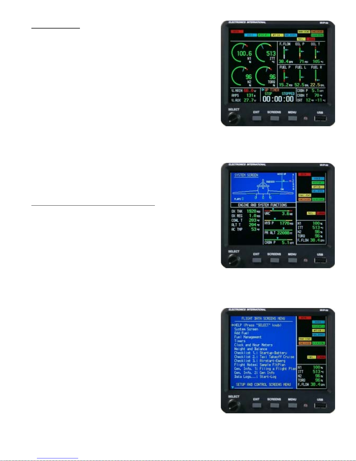
Main Engine Screen (see section 2.0): The Main Engine Screen
displays most of the engine and aircraft instruments and annunciators
monitored by the MVP . This is the screen the MVP displays after
power-up and is the screen the pilot will view for most of the flight.
System Screen (see section 3.0): The System Screen is intended
to display functions that do not need to be displayed continuously . If
any function on the System Screen goes into the red or yellow , a
“System” annunciator on the Main Engine Screen will blink. In this
way the pilot is alerted of a potential problem and should view the
System Screen for further information.
Flight Data Screen Menu (see section 4.0): The Flight Data
Screen Menu provides access to screens designed to assist the pilot
in aircraft and engine operation, flight management, procedures, rules
and regulations and a wealth of other information. All of the Flight
Data Screens are displayed against a blue background and will be
displayed on the left side of the MVP screen. A full set of
annunciators and five primary engine instruments will be displayed on
the right side of the screen against a black background. The
annunciators are divided into two groups. The top right portion of the
screen displays the system annunciator’s setup by the installer . The
middle right portion of the screen displays annunciators associated
with the instruments displayed on the Main screen.
System Screen
Flight Data Screen Menu
4
If any function on the Main or System Screen goes into the red or
yellow , the appropriate annunciator will blink, the external warning
light will blink and an appropriate voice warning will be played. In
this way the pilot is immediately alerted of a potential problem and
should view the appropriate screen for further information.
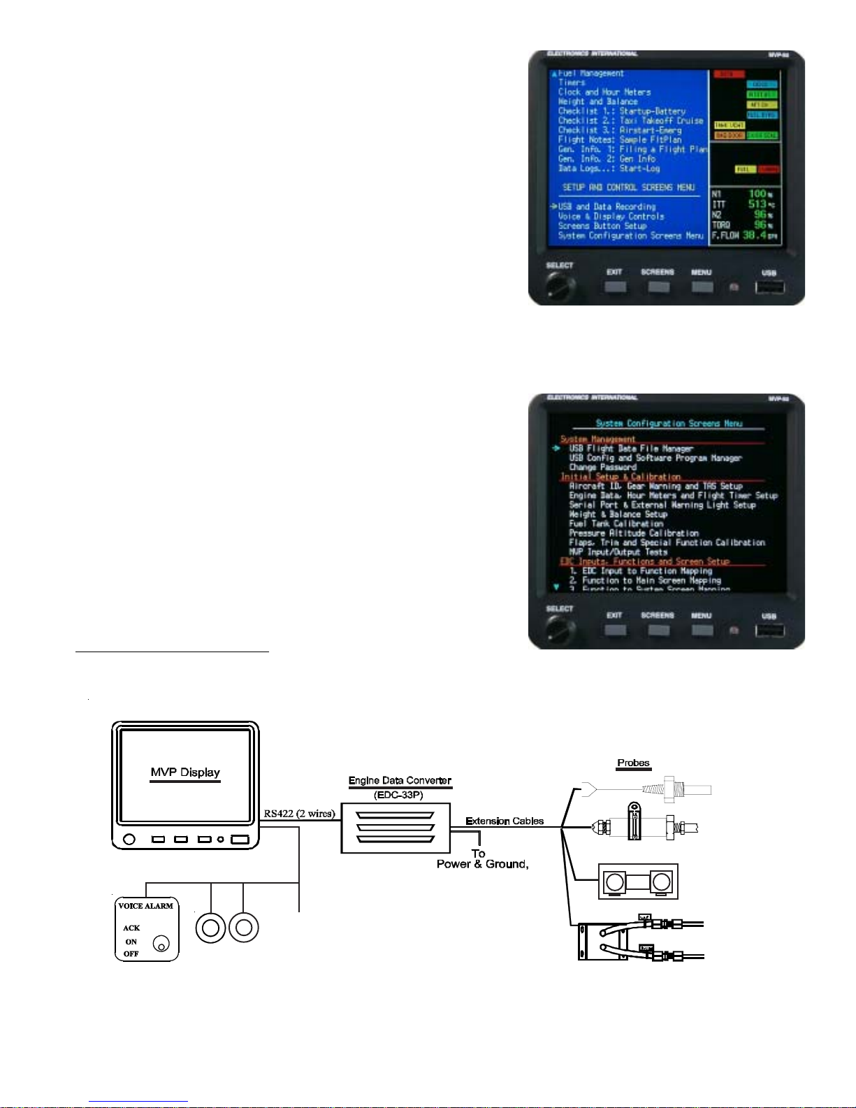
Setup and Control Screen Menu (see section 5.0): The Setup
and Control Screen Menu provides access to screens containing
parameters that the pilot may want to change from time to time during
a flight (brightness control, screen button setup, etc.).
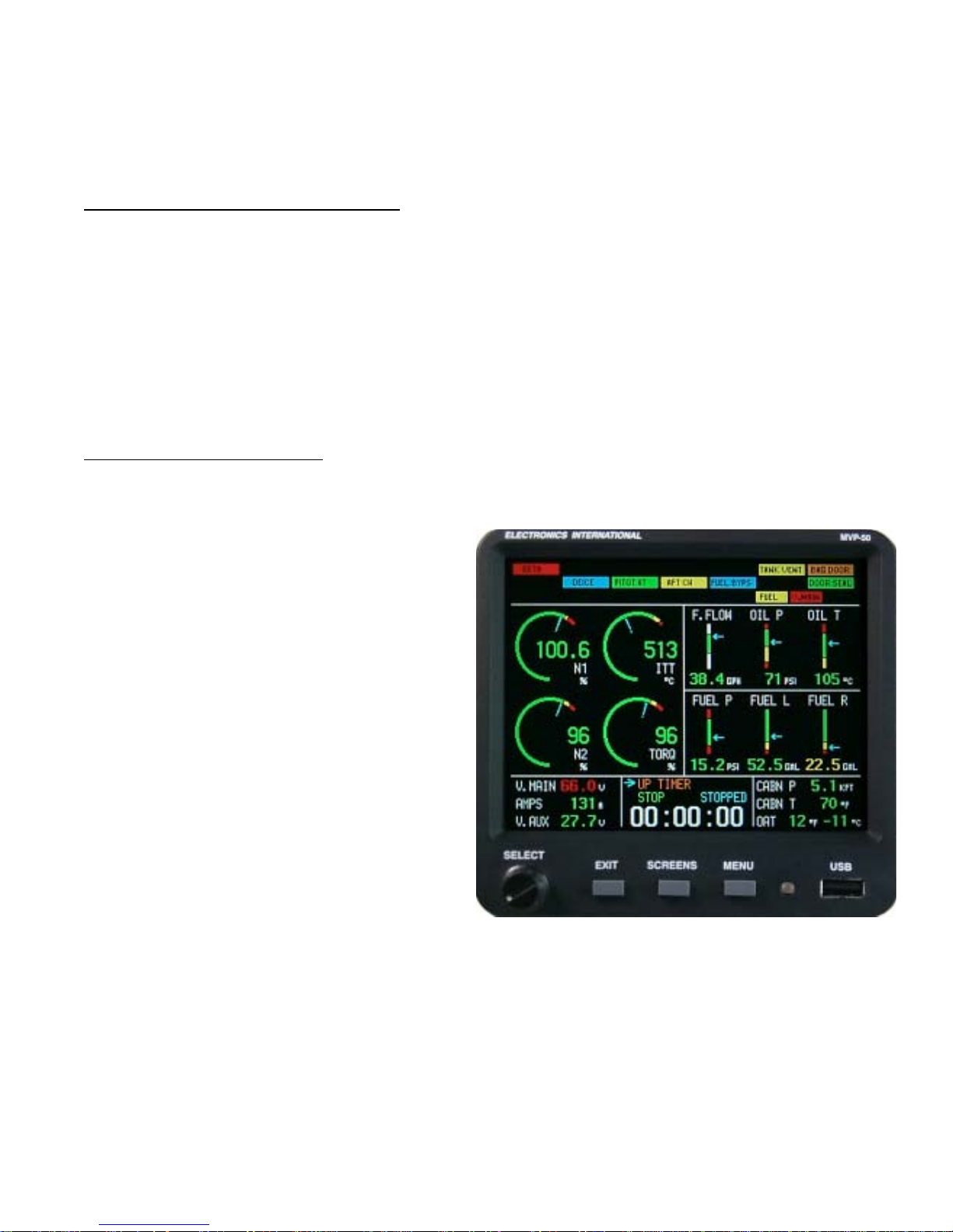
System Configuration Screens (see section 6.0): The System
Configuration Screen Menu provides a list of screens used to
configure the MVP for almost any aircraft. These screens allow the
installer to view the setup functions, screens, instrument markings,
limitations, weight and balance setup, flap and trim calibration, fuel
tank calibration and other system setup requirements. The “MVP-
50T Setup Checklist” will guide the installer through the necessary
steps to set up the MVP for a specific aircraft. The “MVP-50T
Setup Checklist” is provided on a separate blue tag-board T o make
a change to data on any one of these screens requires the
appropriate password (see the Password Protection section of this
manual).
Setup and Control Screen Menu
All of the System Configuration Screens will be displayed with a
black background and the annunciators and engine instruments will
not be displayed.
1.3 System Hardware:
To
Pwr & Gnd
Warning
Master
and
Warning
Caution
Light
Lights
GPS
Auto Panel
System Configuration Screens
5

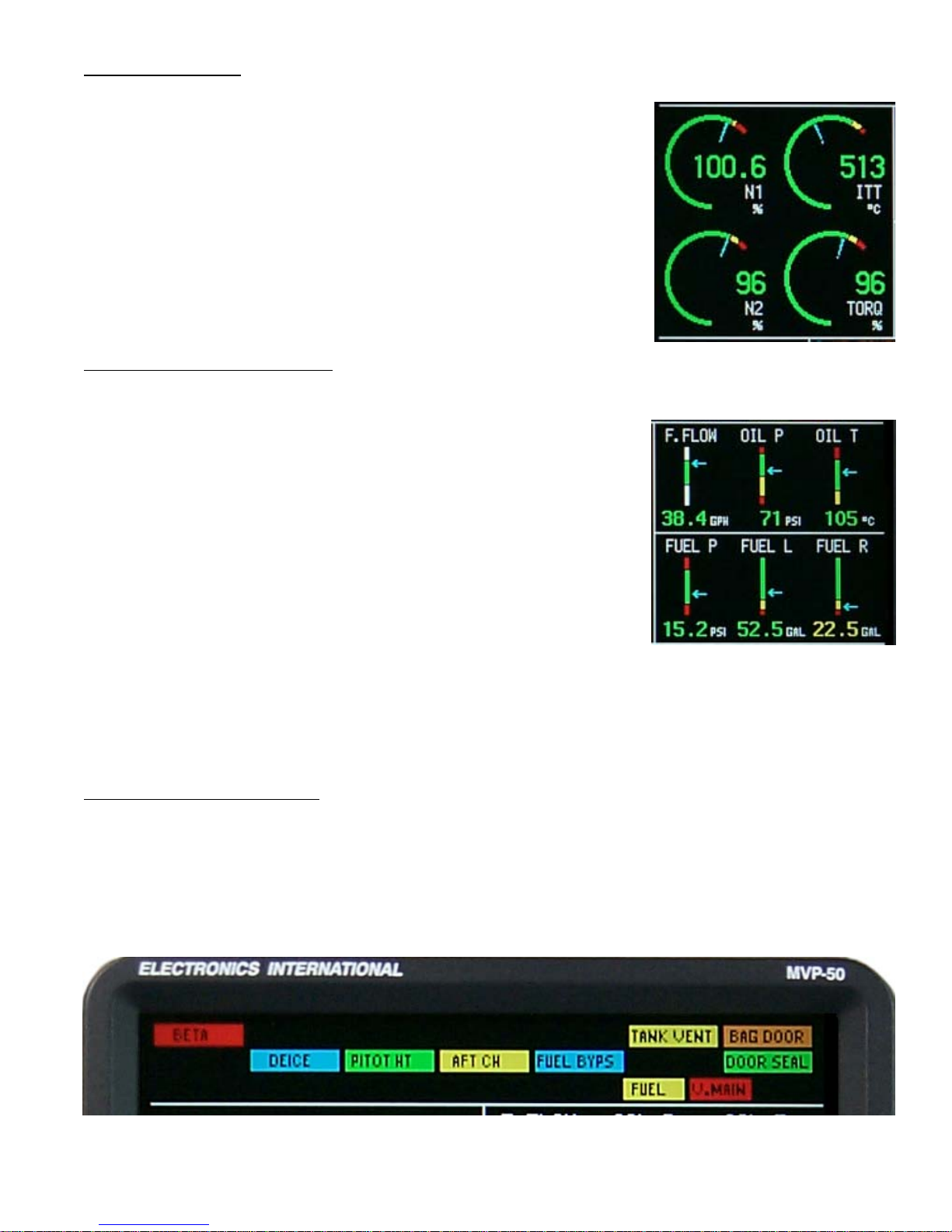
The MVP hardware consists of the following three groups of components:
A. Probes, T ransducers and Extension Cables – These components are used to measure pressures,
temperatures, fuel flow , volts, amps, fuel levels and many other engine and aircraft system functions. The
analog signals produced by the transducers and probes are routed through the Extension Cables to various
EDC inputs.
B. EDC (Engine Data Converter) – The EDC converts the analog signals from the probes and transducers
to a digital format. This data is transmitted three times per second via a two-wire RS422 cable to the MVP
Display . A second EDC may be installed to increase the MVP’ s capability .
C. MVP Display – The MVP receives, processes and displays the RS422 EDC data on its TFT color
display . In addition, the MVP receives GPS data, interfaces with the Voice W arning Control Panel and
monitors the external back light control line. Also, the MVP transmits fuel data to the GPS and controls the
external Master W arning Light.
The MVP reduces the number of panel-mounted instruments from around 15 to only 1 and provide 24
annunciators. The EDC can reduce the total number of wires routed to the aircraft instrument panel by 100 or
more.
1.4 SELECT Knob and Button Operation:
SELECT Knob: The SELECT knob can be rotated or pressed. Depending on the screen and field being
viewed, rotating the knob can move an arrow , select a digit, or change a digits value. Pressing the SELECT knob
will choose the highlighted item.
EXIT Button: Pressing the EXIT button will exit you out of a specific operation. Repeated presses will exit you
out of the current screen, returning you to the previous screen viewed. You can always return to the Main Engine
Instrument Screen by repeatedly pressing the EXIT button.
SCREENS Button: Pressing the SCREENS button sequences the MVP through a list of Flight Data Screens.
The Flight Data Screens that will be displayed can be pre-selected on the Screens Button Setup page. The
SCREENS button allows you quick access to the screens you use most frequently . T o navigate to the “Screens
Button Setup” page start by viewing the Main Engine Screen, push the Menu button and select the Screens Button
Setup near the bottom of the page.
MENU Button: The MENU button displays the menu for the current screen viewed (providing a menu is available
for that screen). Some screens do not have a menu available. If the MENU button is pushed while displaying the
Main Engine Screen, the “Flight Data Screens Menu” will be displayed.
6

1.5 Display Dimming:
The MVP provides two methods of controlling the brightness of the TFT display. When the “Brightness Control” is
set for “Auto Dimming” the display will automatically dim as the ambient light reduces. The light sensor is located
next to the USB port on the MVP front panel.
When the “Brightness Control” is set for “External” an external control pot can be used to control the brightness of
the MVP display . The Electronics International CP-1-MVP Intensity Control Pot can be used for this purpose.
Note: The MVP display will be at full intensity if the “Brightness Control” is set to “External” and there is no
external pot connected to the MVP .
The Brightness Control can be found on the “V oice & Display Controls” screen. T o navigate to the “V oice &
Display Controls” screen start by viewing the Main Engine Screen, push the Menu button and select the Voice &
Display Controls screens near the bottom of the page.
1.6 Cleaning the Screen:
The MVP incorporates a flat panel full color TFT display , which should be protected from being scratched. The
TFT display should be cleaned using only isopropyl alcohol and a soft cleaning cloth. Individually wrapped lenscleaning tissue (used to clean glasses or plastic lenses) works best.
7

Main Engine ScreenMain Engine Screen
Main Engine Screen
Main Engine ScreenMain Engine Screen
2.1 Power-up Add Fuel Message:
2.2 Main Screen Layout:
2.3 Arc Gauges:
2.4 Vertical Strip Gauges:
2.5 Annunciators (CAS):
2.6 Digital Instruments:
2.7 External Master Caution and Warning Lights:
2.02.0
2.0
2.02.0
2.8 Voice Alarm Control Panel (Experimental Only):
2.9 Disabling a Display:
8
The Main Engine Screen provides the aircraft system and engine instruments you will view most frequently during a
flight. There is important information published in the Important Notice section (found in the front of this
manual) that must be read before operating this instrument. Please read the Important Notice section at this
time.
2.1 Power-up Add Fuel Message:
An add fuel message located in the lower center section of the screen will appear when the MVP is powered up.
The purpose of this message is to remind you to update the fuel computer if you have added fuel to the aircraft. The
MVP not only measures and displays the fuel in the fuel tanks but it also displays the fuel on-board the aircraft
calculated from fuel flow . This allows you to cross check fuel readings to insure accuracy .
Note: As long as the “Add Fuel Message” is displayed all the annunciators will be lit. This feature provides a test
for the annunciators.
2.2 Main Screen Layout:
The Main Engine Screen is laid out in four areas:
Arc Gauges (see section 2.3): The N1, N2,
ITT and T orque gauges will be displayed in the
center left portion of the Main EngineScreen.
V ertical S trip Gauges (see section 2.4): A
series of V ertical Strip Gauges (with digital
readouts) are located in the center right portion
of the Main Engine Screen.
Annunciators (see section 2.5): Fourteen
System/Engine Annunciators are displayed in
two rows at the top of the screen. T en
additional Main Engine Screen Annunciators
are located below these fourteen annunciators.
Digital Instruments (see section 2.6): At
the bottom of the Main Engine Screen are three
sections for displaying additional instruments in
a digital format.
10
2.3 Arc Gauges:
The Arc Gauges incorporate a digital readout and an analog arc. The color of
the digital readout will reflect the current operating level of the instrument (i.e.,
if the N1 is operating in the red, the digital readout will be red).
The digital display can be set to blink when a functions operating level reaches
a yellow and/or red operating range. To stop the blinking, push any button, or
rotate the SELECT knob. Also, acknowledging a voice warning using the
external “Voice Alarm Control Panel” will stop the blinking of any digital
display.
2.4 Vertical Strip Gauges:
The V ertical S trip Gauges provide the following features:
A. The colored operating ranges shown on the Vertical Strip are
programmable and may be set up for any aircraft.
B. Each V ertical S trip Gauge features an arrow marking the current
operating level. Also, the arrow allows the pilot to interpret rate
and trend information and provides field of vision.
C. A digital display is featured with each Vertical Strip Gauge.
D. The digital display can be set to blink when a function’s operating
level reaches a yellow and/or red operating range. To stop the blinking, push any button, or rotate the
Select knob. Also, acknowledging a voice warning using the external “Voice Alarm Control Panel” will
stop the blinking of any digital display.
2.5 Annunciators (CAS):
An EDC temperature or resistive fuel level channel can be connected to a switch, relay or device via a VI-221
interface circuit. The signals from these devices are usually high or low and can be used to generate an annunciator .
An annunciator can be displayed in any color for a high or low signal. If the color white was selected for one of the
signal levels, the annunciator will not be displayed for that signal level.
11

At the top of the Main Engine Screen are three rows of annunciators. These annunciators makeup a Crew Alert
System (CAS). The top two rows of annunciators are defined by the installer . The bottom row of annunciators is
associated with functions displayed on the Main Engine Screen. Also, at the far right of the bottom row is a
“System” annunciator . If any
function found on the System Screen goes into the red or yellow , the “System”
annunciator will blink in the appropriate color. In this way the pilot is alerted of a potential problem and should view
the System Screen for further information and to stop the “System” annunciator from blinking.
If any
function found on the Main Engine Screen goes into the red or yellow , the appropriate annunciator in the
bottom row will blink.
If any annunciator found on the top two rows of the Main Engine Screen goes to any color other than white, the
appropriate annunciator will light. If the lit color is red or yellow , the appropriate annunciator will also blink.
T o stop the blinking of any annunciator, push any button, or rotate the SELECT knob while viewing the Main Engine
Screen. Also, acknowledging a voice warning using the external “V oice Alarm Control Panel” will stop the blinking
regardless of what screen you are viewing.
Note: To test the annunciators, push and hold the “Exit” button. All available annunciators will light.
2.6 Digital Instruments:
At the bottom of the Main Engine Screen are three areas for digital instruments. The bottom center section may be
switched between Trim (includes Gear and Flaps), Clocks, Flight Timer, Down Timer and Up Timer. Push and turn
the “Select” knob to display the various functions.
If a function displayed on a digital instrument goes in the red or yellow operating range, the digital display will blink
the appropriate color. To stop the blinking, push any button, or rotate the SELECT knob while viewing the Main
Engine Screen. Also, acknowledging a voice warning using the external “Voice Alarm Control Panel” will stop the
blinking regardless of what screen you are viewing.
2.7 External Master Caution and Warning Lights:
A red external W arning Light and a yellow Caution Light (provided with the MVP) may be mounted
in front of the pilot, high on the aircraft instrument panel. These lights provide a heads-up visual
warning. If programmed to do so, the red W arning Light will blink any time the operating level of
any monitored function reaches a red operating limit and the yellow Caution Light will blink any time
the operating level of any monitored function reaches a yellow operating limit.
Pushing any button, or rotating or pushing the Select knob when the Caution or W arning Light is
blinking will acknowledge the blinking and the blinking will stop. Also, acknowledging a voice warning using the
external “V oice Alarm Control Panel” will stop the blinking of the Caution and W arning Lights.
R
MVP-50P
Y
Acknowledging a yellow blinking display will cause the yellow Caution Light to go out. Acknowledging a red
blinking display will cause the red W arning Light to stop blinking and go solid red. At any time another function
reaches a red and/or yellow operating limit the approprate Caution or W arning Light will once again blink.
12

The “4. Redlines, Limits and Color Setup” screen and the “Serial Port & External W arning Light Setup” screen
provides fields to set the operation of the Caution and W arning lights. Changes in these screens are password
protected.
As with any warning system, it is important that there are no false alarms. False alarms can desensitize a pilot to all
alarms, which can cause a serious situation to go undetected. Setting proper red and yellow limits for each function
is a key step in eliminating false alarms.
2.8 Voice Alarm Control Panel:
The Voice Alarm Control Panel is an external panel used to control the voice warnings provided
by the MVP . The MVP voice warning system is a powerful system that provides an immediate
and intelligent audible warning regardless of the pilot’ s head position or focus. The instant an
operating level of any function reaches a red and/or yellow operating limit, a chime will sound in
the headset and a pleasant female voice will annunciate a phrase, such as: “Check Oil
Pressure,” or “Check Fuel Pressure.”
T ask List: If two or more alarms are activated, the alarms are placed on a task list and are announced one at a
time with a one-second delay between alarms. After the last alarm on the task list is announced a five-second delay
will occur. The alarms are then once again announced in order.
Power-up Announcement: When the MVP is powered up and the Voice Alarm Control Panel switch is placed in
the “ON” position, the MVP will announce, “Voice Annunciator enabled. Have a nice flight.” This announcement
will be made only once, at the beginning of each flight.
Acknowledging and Silencing an Alarm for One Minute: T o acknowledge and silence an alarm, push the
switch on the Voice Alarm Control Panel momentarily to the “ACK” (acknowledge) position. A high tone beep will
be heard in the headset and all active Red warnings will be silenced for one minute. This is handy if you don’t want
to permanently shut off any alarms but you need silence for one minute in order to deal with other pressing matters.
After one minute the silenced Red warnings (if still active) once again will be announced in the headset.
Once a YELLOW caution is acknowledged it will not reoccur. If the “Red & Yellow Warning Logic” field (found
in the “4. Redlines, Limits and Color Setup” screen) has been set to “Disabled,” a voice alarm will not be provided.
During the time one or more alarms are silenced, any newly activated Red or Y ellow alarm will be announced
immediately in spite of the minute of silence. T o silence this new cauton or warning alarm, once again push the
Control Panel Switch to the “ACK” position, which will silence the new alarm and all active Red warnings for one
minute.
Acknowledging and Silencing an Alarm for 10 Minutes: T o acknowledge and silence any active Red warning
for 10 minutes, push the Voice Alarm Control Panel switch to the “ACK” position three times within three seconds
or less. On the third push, a low tone boop will be heard in the headset, indicating that all active Red warnings will
be silenced for 10 minutes.
T urning the V oice W arning System “OFF”: T o disable the MVP Voice W arning System, silence all voice
alarms in the headset and reset any silence delay times and Yellow cautions, simply set the V oice Alarm Control
13

Panel switch to the “OFF” position. When the Control Panel Switch is once again set to the “ON” position, the
MVP will announce “Voice Annunciator enabled.” This will be followed by the announcement of any active alarms.
Adjusting the V olume of the Voice Warnings: The “Voice & Display Controls” screen provides a control to
adjust the volume level of the voice warnings. T o navigate to the “Voice & Display Controls” screen start by
viewing the Main Engine Screen, push the Menu button and select the “V oice & Display Controls” screen near the
bottom of the page.
False Alarms: As with any warning system, it is important there are no false alarms. False alarms can desensitize a
pilot to all alarms, which can cause a serious situation to go undetected. Setting proper red and yellow limits for
each function is a key step in eliminating false alarms.
2.9 Disabling a Display:
Any display shown on the Main Engine or System Screen may be disabled. This allows an improperly operating
function on the MVP to be designated “DISABLED.” To disable an MVP instrument display , see the “4. Redlines,
Limits and Color Setup” screen. This feature is password protected.
14

System ScreenSystem Screen
System Screen
System ScreenSystem Screen
3.1 Trim Indicator:
3.2 Flap Indicator:
3.3 Gear Position Indicator:
3.4 Gear Up Warning:
3.5 Engine and System Functions:
3.6 Annunciators (CAS):
3.7 Five Digital Instruments from the Main Screen:
3.03.0
3.0
3.03.0
16
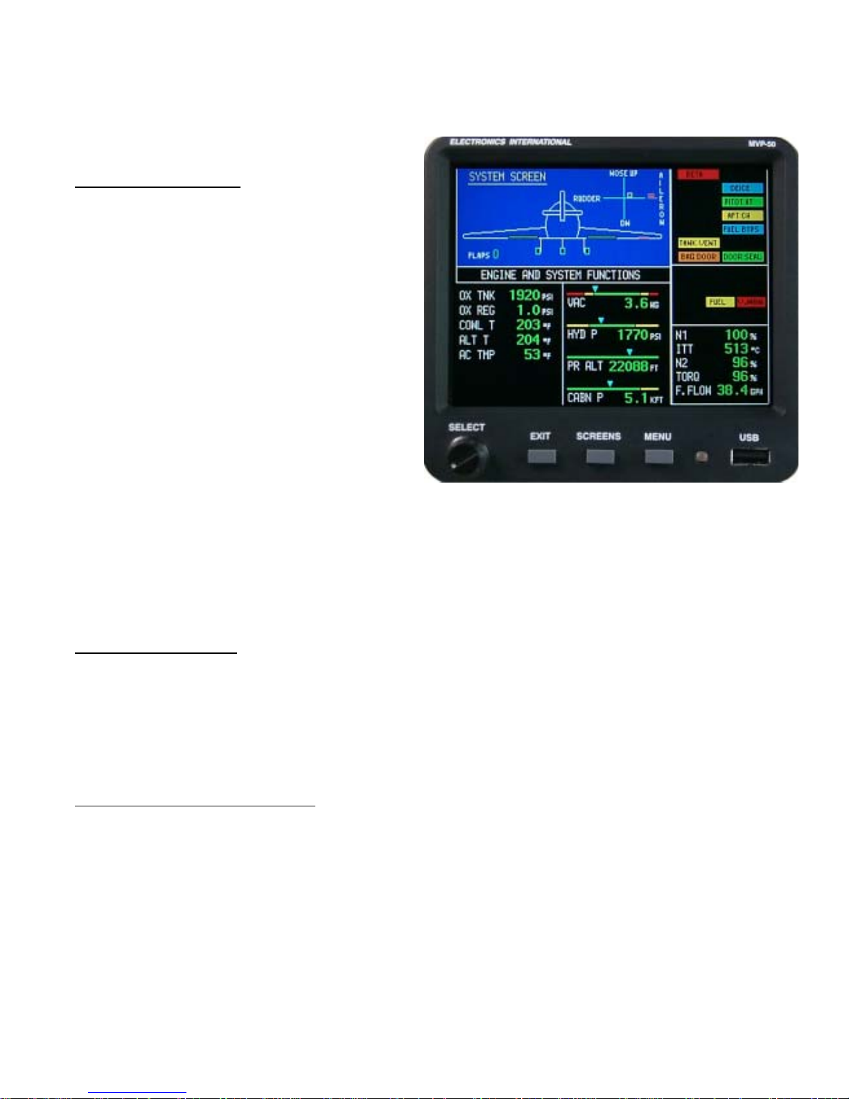
The System Screen is intended to display system functions and the configuration of the aircraft. This gives the pilot
one location (i.e., one screen) to find all of the pertinent system functions and configuration information on the
aircraft. Normally these functions would not need to be displayed continuously . The following features in the
System Screen are provided:
3.1 Trim Indicator:
The Trim Indicator located in the top right corner of
the System Screen provides elevator, rudder , and
aileron trim indications. Only the applicable trim
functions for your aircraft may be displayed.
When the elevator is trimmed the yellow box will
move up or down on the vertical line. The yellow
box should move up as the nose of the aircraft is
trimmed up. Neutral is in the center of the horizontal
line.
When the rudder is trimmed the yellow box will
move right or left on the horizontal line. The yellow
box should move right as the nose of the aircraft is
trimmed right. Neutral is in the center of the vertical line.
When the ailerons are trimmed the bar graph to the right of the display will move up or down from the horizontal
line. The bar graph should move up as the right wing is trimmed up. Neutral is indicated by a single bar on the
horizontal line.
3.2 Flap Indicator:
The flaps are shown in the wing roots of the pictured aircraft. As the flaps are extended the displayed flaps in the
picture will move downward. Also, the Flap Angle will be displayed in degrees just under the left flap on the
display.
3.3 Gear Position Indicator:
The landing gears are displayed in the pictured aircraft. When the wheels are retracted, the pictured gears will be
shown in the down position. During transition the word “UNSAFE” will be shown in red. If a gear is hung, it will
be shown in the up position with the word “UNSAFE.”
The MVP Gear Position Indicator is not a replacement for the Gear Lights located on the aircraft instrument panel.
The MVP Gear Position Indicator should be used only as a backup. It is provided to give the pilot a single location
to view the aircraft configuration. The Gear Lights located on the aircraft instrument panel should be viewed before
landing.
18

3.4 Gear Up Warning:
The MVP can provide a gear up voice warning if the following functions are monitored: Gear Position, N1 and
Airspeed. As you enter the pattern and reduce N1 the aircraft’ s Airspeed will start dropping. If N1 and Airspeed
drop below a programmed level (set for your aircraft) and the Landing Gear is not down and locked, you will get a
voice warning.
This method allows you to perform low power, fast descents and high power , low speed climbs without annoying
warnings. The setup for the Gear W arning is covered in the Appendix. If you have a retractable gear aircraft, this
feature will sooner or later pay for the MVP many times over .
3.5 Engine and System Functions:
The left side of the display area provides up to seven digital instruments or annunciators (such as Canopy , Baggage
Door, Landing Lights, Rotating Beacon, etc.). The right side of the display area provides up to four horizontal strip
gauges with digital displays. All of these instruments may be configured with various functions or annunciators.
3.6 Annunciators (CAS):
The top right portion of the System Screen provides fourteen installer-defined annunciators and the center right
portion of the screen provides nine Main Engine Screen annunciators. All of these annunciators are the same as
shown on the Main Engine Screen. If any function or annunciator goes into the red or yellow , the appropriate
display will blink. In this way the pilot is alerted of a potential problem and should view the appropriate screen for
further information. Annunciator operation was covered in a previous section of this manual.
3.7 Five Digital Instruments from the Main Screen:
The bottom right portion of the System Screen provides up to five primary functions from the Main Engine Screen.
If any function goes into the red or yellow , the appropriate display will blink. In this way the pilot is alerted of a
potential problem and should view the Main Engine Screen for further information.
19

Flight Data ScreensFlight Data Screens
Flight Data Screens
Flight Data ScreensFlight Data Screens
4.1 “Help” Screen:
4.2 System Screen:
4.3 “Add Fuel” Screen:
4.4 “Fuel Management” Screen:
4.5 “Timer” Screen:***
4.6 “Clock and Hour Meters” Screen:
4.7 “Weight and Balance” Screen:
4.04.0
4.0
4.04.0
4.8 “Checklist” Screens:
4.9 “Flight Notes” Screens:
4.10 “Gen. Info.” Screens:
4.11 “Data Logs” Screens:
20
 Loading...