

Page 1
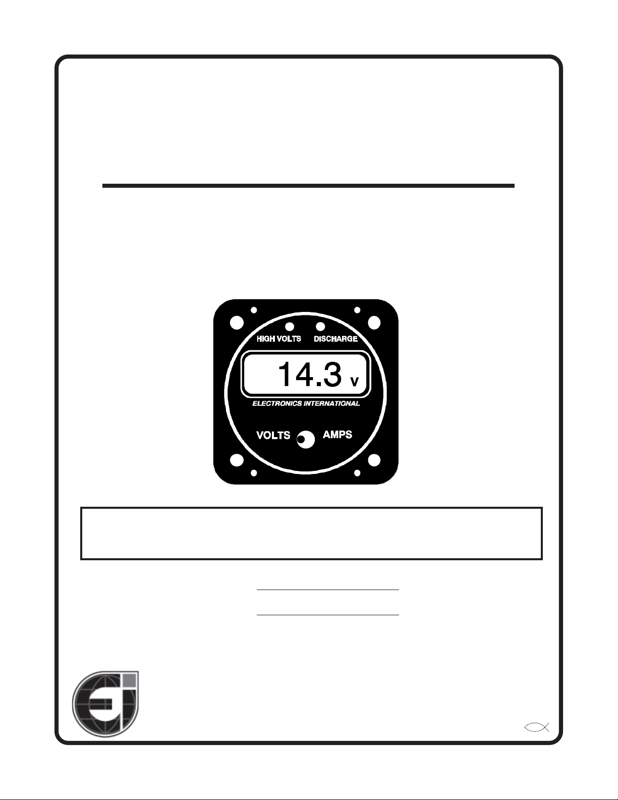
Volts / AmpsVolts / Amps
Volts / Amps
Volts / AmpsVolts / Amps
(Primary Instruments)(Primary Instruments)
(Primary Instruments)
(Primary Instruments)(Primary Instruments)
(VA-1A, VA-1A-XX & RSVA-3)(VA-1A, VA-1A-XX & RSVA-3)
(VA-1A, VA-1A-XX & RSVA-3)
(VA-1A, VA-1A-XX & RSVA-3)(VA-1A, VA-1A-XX & RSVA-3)
Operating and Installation InstructionsOperating and Installation Instructions
Operating and Installation Instructions
Operating and Installation InstructionsOperating and Installation Instructions
S0224921
OI 041032 and II 040934
S/N: ~74000 and up.
4/9/83
Rev. C: 2/24/92 ***
You must read this manual before installing or operating the instrument. This
manual contains warranty and other information that may affect your decision
to install this product and/or the safety of your aircraft.
Model:Model:
Model:
Model:Model:
S/N:S/N:
S/N:
S/N:S/N:
Electronics International Inc. Electronics International Inc.
Electronics International Inc.
Electronics International Inc. Electronics International Inc.
63296 Powell Butte Hwy • Bend, OR 97701 • (541) 318-6060 • Buy-EI.com 63296 Powell Butte Hwy • Bend, OR 97701 • (541) 318-6060 • Buy-EI.com
63296 Powell Butte Hwy • Bend, OR 97701 • (541) 318-6060 • Buy-EI.com
63296 Powell Butte Hwy • Bend, OR 97701 • (541) 318-6060 • Buy-EI.com 63296 Powell Butte Hwy • Bend, OR 97701 • (541) 318-6060 • Buy-EI.com
®®
®
®®
Page 2

Page 3
Important NoticeImportant Notice
Important Notice
Important NoticeImportant Notice
***** MUST READ ********** MUST READ *****
***** MUST READ *****
***** MUST READ ********** MUST READ *****
If you think it is not important to read this manual, you're wrong!If you think it is not important to read this manual, you're wrong!
If you think it is not important to read this manual, you're wrong!
If you think it is not important to read this manual, you're wrong!If you think it is not important to read this manual, you're wrong!
contains important installation information that may affect the safety of your air-contains important installation information that may affect the safety of your air-
contains important installation information that may affect the safety of your air-
contains important installation information that may affect the safety of your air-contains important installation information that may affect the safety of your aircraft, delay your installation or affect the operation of your instrument. You craft, delay your installation or affect the operation of your instrument. You
craft, delay your installation or affect the operation of your instrument. You
craft, delay your installation or affect the operation of your instrument. You craft, delay your installation or affect the operation of your instrument. You
read this manual prior to installing your instrument. read this manual prior to installing your instrument.
read this manual prior to installing your instrument.
read this manual prior to installing your instrument. read this manual prior to installing your instrument.
installation instructions is the sole responsibility of the installer/pilot and mayinstallation instructions is the sole responsibility of the installer/pilot and may
installation instructions is the sole responsibility of the installer/pilot and may
installation instructions is the sole responsibility of the installer/pilot and mayinstallation instructions is the sole responsibility of the installer/pilot and may
render the STC invalid.render the STC invalid.
render the STC invalid.
render the STC invalid.render the STC invalid.
Read the Warranty / AgreementRead the Warranty / Agreement
Read the Warranty / Agreement. There is information in the Warranty / Agreement that may alter
Read the Warranty / AgreementRead the Warranty / Agreement
your decision to install this product.
install this productinstall this product
install this product. This product may be returned for a refund. Contact Electronics International inc. for
install this productinstall this product
details.
Check that the instrument make and model marked on the side of the instrument and on the invoice are
correct before starting the installation. The VA-1A is an internal shunt unit and the VA-1A-XX is an
external shunt unit (“XX” = your aircraft shunt value in amps).
It is possible for any instrument to fail thereby displaying inaccurate high, low or jumpy readings.
Therefore, you must be able to recognize an instrument failure and you must be proficient in operating your
aircraft safely in spite of an instrument failure. If you do not have this knowledge, contact the FAA or a
local flight instructor for training.
If you do not accept the terms of the Warranty / Agreement, do notIf you do not accept the terms of the Warranty / Agreement, do not
If you do not accept the terms of the Warranty / Agreement, do not
If you do not accept the terms of the Warranty / Agreement, do notIf you do not accept the terms of the Warranty / Agreement, do not
Any deviation from theseAny deviation from these
Any deviation from these
Any deviation from theseAny deviation from these
This manual This manual
This manual
This manual This manual
MustMust
Must
MustMust
The ability for this product to detect a problem is directly related to the pilots interpretation and observation
skills.
The pilot
to operate the aircraft that does not know the operation of this product. Keep the Operating Manual in the
aircraft at all times.
must must
must understand the operation of this product before flying the aircraft. Do not allow anyone
must must
Page 4

Page 5

ContentsContents
Contents
ContentsContents
WARRANTY ................................................................................................................... 2
VA-1A, VA-1A-XX Operating Instructions................................................................. 3
Features ......................................................................................................................................................... 3
VA-1A Installed in the Battery Lead ........................................................................................................ 4
VA-1A Installed in the Alternator Lead ................................................................................................... 6
VA-1A, VA-1A-XX Installation Instructions............................................................... 8
General Information.................................................................................................................................... 8
Installation .................................................................................................................................................... 9
1. Important Information and Initial Check Out ............................................................................... 9
2. Instrument Set Up ............................................................................................................................... 9
3. Determine how the VA Unit will be installed in your aircraft's electrical system .................... 9
4. Install the External Shunt (External Shunt Unit Only, VA-1A-XX) ......................................... 1 2
5. Route the Circular Connectors....................................................................................................... 12
6. Route the Power and Ground Wires.............................................................................................. 12
7. Route the Backlight Wires ............................................................................................................... 12
8. Route the Shunt Wires (External Shunt Unit Only, VA-1A-XX) ............................................... 1 3
9. Connect the Large Shunt Wires (Internal Shunt Unit Only, VA-1A) ....................................... 1 3
10. Install the Instrument in the Panel ................................................................................................. 13
11. Connect the Circular Connector to the Instrument ................................................................... 1 3
12. Ground Tes: ...................................................................................................................................... 13
Troubleshooting.............................................................................................................14
VA-1A (Internal Shunt Unit) Wiring Diagram ......................................................... 1 6
VA-1A-XX (External Shunt Unit) Wiring Diagram ................................................. 1 7
VA-1A and VA-1A-XX Circular Connector..............................................................18
RSVA-3 Installation Instructions................................................................................. 19
1. Install the External Shunt .................................................................................................................... 19
2. Install the VA-1A-XX Instrument ...................................................................................................... 19
3. Route the Shunt Wires ......................................................................................................................... 19
4. Route the Instrument Wires to the RSVA-3 ..................................................................................... 19
5. Install the RSVA-3 in the Panel.......................................................................................................... 20
6. Ground Test ........................................................................................................................................... 20
RSVA-3 Wiring Diagram .............................................................................................21
RSVA-3 Circular Connector ........................................................................................22
Specifications and Operating Features .......................................................................23
STC Information ..................................................................................... See Back Pages
1
Page 6

WW
arar
W
WW
Electronics International Inc. warrants this instrument and system components to be free from defects
in materials and workmanship for a period of one year from the user invoice date. Electronics International Inc. will repair or replace any item under the terms of this Warranty provided the item is
returned to the factory prepaid.
1. This Warranty shall not apply to any product that has been repaired or altered by any person other
than Electronics International Inc., or that has been subjected to misuse, accident, incorrect wiring,
negligence, improper or unprofessional assembly or improper installation by any person.
ranty does not cover any reimbursement for any person’s time for installation, removal,ranty does not cover any reimbursement for any person’s time for installation, removal,
ranty does not cover any reimbursement for any person’s time for installation, removal,
ranty does not cover any reimbursement for any person’s time for installation, removal,ranty does not cover any reimbursement for any person’s time for installation, removal,
assembly or repair.assembly or repair.
assembly or repair. Electronics International retains the right to determine the reason or cause for
assembly or repair.assembly or repair.
warranty repair.
2. This warranty does not extend to any machine, vehicle, boat, aircraft or any other device to which
the Electronics International Inc. product may be connected, attached, interconnected or used in
conjunction with in any way.
3. The obligation assumed by Electronics International Inc. under this warranty is limited to repair,
replacement or refund of the product, at the sole discretion of Electronics International Inc.
4. Electronics International Inc. is not liable for expenses incurred by the customer or installer due to
factory updates, modifications, improvements, upgrades, changes, or any other alterations to the
product that may affect the form, fit, function or operation of the product.
ranty / ranty /
ar
ranty /
arar
ranty / ranty /
AgrAgr
Agr
AgrAgr
eementeement
eement
eementeement
This war-This war-
This war-
This war-This war-
5. Personal injury or property damage do to misinterpretation or lack of understanding this product is
must must
solely the pilots responsibility. The pilot
the aircraft. Do not allow anyone to operate the aircraft that does not know the operation of this
product. Keep the Operating Manual in the aircraft at all times.
6. E. I. Inc. is not responsible for shipping charges or damages incurred under this Warranty.
7. No representative is authorized to assume any other liability for Electronics International Inc. in
connection with the sale of Electronics International Inc. products.
If you do not agree to and accept the terms of this warranty, you may return theIf you do not agree to and accept the terms of this warranty, you may return the
If you do not agree to and accept the terms of this warranty, you may return the
8.
If you do not agree to and accept the terms of this warranty, you may return theIf you do not agree to and accept the terms of this warranty, you may return the
product for a refund.product for a refund.
product for a refund.
product for a refund.product for a refund.
This Warranty is made only to the original user.
OTHER WARRANTIES OR OBLIGATIONS: EXPRESS OR IMPLIED. MANUFAC-OTHER WARRANTIES OR OBLIGATIONS: EXPRESS OR IMPLIED. MANUFAC-
OTHER WARRANTIES OR OBLIGATIONS: EXPRESS OR IMPLIED. MANUFAC-
OTHER WARRANTIES OR OBLIGATIONS: EXPRESS OR IMPLIED. MANUFAC-OTHER WARRANTIES OR OBLIGATIONS: EXPRESS OR IMPLIED. MANUFACTURER EXPRESSLY DISCLAIMS ALL IMPLIED WARRANTIES OF MERCHANT-TURER EXPRESSLY DISCLAIMS ALL IMPLIED WARRANTIES OF MERCHANT-
TURER EXPRESSLY DISCLAIMS ALL IMPLIED WARRANTIES OF MERCHANT-
TURER EXPRESSLY DISCLAIMS ALL IMPLIED WARRANTIES OF MERCHANT-TURER EXPRESSLY DISCLAIMS ALL IMPLIED WARRANTIES OF MERCHANTABILITY OR FITNESS FOR A PARTICULAR PURPOSE. PURCHASER AGREESABILITY OR FITNESS FOR A PARTICULAR PURPOSE. PURCHASER AGREES
ABILITY OR FITNESS FOR A PARTICULAR PURPOSE. PURCHASER AGREES
ABILITY OR FITNESS FOR A PARTICULAR PURPOSE. PURCHASER AGREESABILITY OR FITNESS FOR A PARTICULAR PURPOSE. PURCHASER AGREES
THAT IN NO EVENT SHALL MANUFACTURER BE LIABLE FOR SPECIAL, INCI-THAT IN NO EVENT SHALL MANUFACTURER BE LIABLE FOR SPECIAL, INCI-
THAT IN NO EVENT SHALL MANUFACTURER BE LIABLE FOR SPECIAL, INCI-
THAT IN NO EVENT SHALL MANUFACTURER BE LIABLE FOR SPECIAL, INCI-THAT IN NO EVENT SHALL MANUFACTURER BE LIABLE FOR SPECIAL, INCIDENTAL OR CONSEQUENTIAL DAMAGES, INCLUDING LOST PROFITS OR LOSSDENTAL OR CONSEQUENTIAL DAMAGES, INCLUDING LOST PROFITS OR LOSS
DENTAL OR CONSEQUENTIAL DAMAGES, INCLUDING LOST PROFITS OR LOSS
DENTAL OR CONSEQUENTIAL DAMAGES, INCLUDING LOST PROFITS OR LOSSDENTAL OR CONSEQUENTIAL DAMAGES, INCLUDING LOST PROFITS OR LOSS
OF USE OR OTHER ECONOMIC LOSS. EXCEPT AS EXPRESSLY PROVIDEDOF USE OR OTHER ECONOMIC LOSS. EXCEPT AS EXPRESSLY PROVIDED
OF USE OR OTHER ECONOMIC LOSS. EXCEPT AS EXPRESSLY PROVIDED
OF USE OR OTHER ECONOMIC LOSS. EXCEPT AS EXPRESSLY PROVIDEDOF USE OR OTHER ECONOMIC LOSS. EXCEPT AS EXPRESSLY PROVIDED
HEREIN, MANUFACTURER DISCLAIMS ALL OTHER LIABILITY TO PURCHASERHEREIN, MANUFACTURER DISCLAIMS ALL OTHER LIABILITY TO PURCHASER
HEREIN, MANUFACTURER DISCLAIMS ALL OTHER LIABILITY TO PURCHASER
HEREIN, MANUFACTURER DISCLAIMS ALL OTHER LIABILITY TO PURCHASERHEREIN, MANUFACTURER DISCLAIMS ALL OTHER LIABILITY TO PURCHASER
OR ANY OTHER PERSON IN CONNECTION WITH THE USE OR PERFORMANCE OFOR ANY OTHER PERSON IN CONNECTION WITH THE USE OR PERFORMANCE OF
OR ANY OTHER PERSON IN CONNECTION WITH THE USE OR PERFORMANCE OF
OR ANY OTHER PERSON IN CONNECTION WITH THE USE OR PERFORMANCE OFOR ANY OTHER PERSON IN CONNECTION WITH THE USE OR PERFORMANCE OF
MANUFACTURER’S PRODUCTS, INCLUDING SPECIFICALLY LIABILITY IN TORT.MANUFACTURER’S PRODUCTS, INCLUDING SPECIFICALLY LIABILITY IN TORT.
MANUFACTURER’S PRODUCTS, INCLUDING SPECIFICALLY LIABILITY IN TORT.
MANUFACTURER’S PRODUCTS, INCLUDING SPECIFICALLY LIABILITY IN TORT.MANUFACTURER’S PRODUCTS, INCLUDING SPECIFICALLY LIABILITY IN TORT.
must understand the operation of this product before flying
must must
THIS WARRANTY IS IN LIEU OF ALLTHIS WARRANTY IS IN LIEU OF ALL
THIS WARRANTY IS IN LIEU OF ALL
THIS WARRANTY IS IN LIEU OF ALLTHIS WARRANTY IS IN LIEU OF ALL
2
Page 7
VV
A-1A,A-1A,
V
A-1A,
VV
A-1A,A-1A,
Operating InstructionsOperating Instructions
Operating Instructions
Operating InstructionsOperating Instructions
VV
A-1A-XXA-1A-XX
V
A-1A-XX
VV
A-1A-XXA-1A-XX
OI 041032
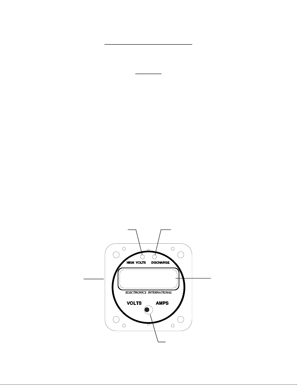
Features
1. 12/24 Volt Select Switch
On the back of the VA-1A is a select switch to set the “High Volts” and “Discharge” warning
features for a 12 or 24 volt system (see Installation Instructions).
2. “High Volts” Warning Light
If the bus voltage rises to 15.3 volts (30.6 volts for a 24-volt system) or higher, a bright red “High
Volts” warning light will alert you of this condition. The high volts feature is sensed off the red
power lead and will function regardless of installation variations or what position the mode switch
is in. If this light is on, an External Warning Line will be pulled low which can be used to activate
an External Warning Light.
0219922
3. “Discharge” Warning Light
If the bus voltage drops below 12.6 volts, (25.2 volts for a 24-volt system) a bright yellow “Discharge” warning light will alert you of this condition. The discharge warning feature is sensed off
the red power lead and will function regardless of installation variations or what position the mode
switch is in. If this light is on, an External Warning Line will be pulled low which can be used to
activate an External Warning Light.
Discharge Warning LightHigh Volts Warning Light
12/24 Volt Select
Switch (on back)
12.312.3
12.3
12.312.3
vv
v
vv
Digital Display
Mode Switch
3
Page 8

Operating Instructions Features
4. Digital Display
The VA-1A comes with 12 and 24 volt digital display back light control lines. The digital display
should be backlit all the time. This will allow it to be viewed easily in dim light. The digital display
is best viewed in high ambient light or direct sunlight.
Voltage will be displayed in 0.1 volt increments and a “V” annunciator will show in the display.
Amperage will be displayed in 0.1 amp increments for the VA-1A and any external shunted unit 60
amps and below (i.e., VA-1A-60 and below). For any external shunted unit above 60 amps (VA1A-70 and above) amperage will be displayed in 1 amp increments. Any time the Mode Switch is
in the “Amps” position, an “A” annunciator will show in the display.
Note: When the VA-1A (-XX) is mounted in the alternator lead and the engine is off, the VA-1A
(-XX) may display up to +/- 0.3 amps. This is due to any leakage current in the alternator and any
offset in the VA-1A (-XX).
5. Mode Switch
The Mode Switch sets the display between “Volts” and “Amps.” The setting of this switch will not
affect the operation of the “High Volts” or “Discharge” warning lights.
VA-1A Installed in the Battery Lead
The two common methods of installing the VA-1A or VA-1A-XX in the electrical system of your
aircraft are in the battery lead and in the alternator lead. Following are the operating characteristics
of the VA-1A installed in the battery lead.
1. Master On, Engine Off
The following describes the operating characteristics of the VA-1A installed in the battery lead
with the master switch on and the engine off.
With the Mode Switch in the “Amps” position, the VA-1A will display the electrical system load on
the aircraft. Since the engine is off, all of the current is being supplied by the battery. The VA-1A
will show a discharging condition (the “Discharge” light will be on) and display an accurate reading of the total current drain from the battery. With all your electrical equipment off, this will be
around 2 to 6 amps. In this mode of operation any piece of electrical equipment can be checked
for proper operation by performing the following steps:
A. Note the amps reading on the VA unit.
B. Turn on the piece of electrical equipment you wish to check.
4
Page 9

Operating Instructions VA-1A Installed in the Battery Lead
C. If this piece of electrical equipment is working properly, you will see an increase in load
current that corresponds to the current that piece of equipment requires. Compare this
current with the current you measured for that same piece of equipment at an earlier date.
Using this method with the digital display of the VA-1A, many important aircraft functions
(strobes, retracts, radios, transponder, ADFs, DMEs, pitot heat, etc.) can be checked from the
pilot’s seat. It would be worthwhile to write down the load current for the entire system and for
each piece of equipment. This would give you something to compare to when you wish to check for
proper operation at a later date. You may also check the entire electrical system with one check
by turning all the electrical equipment on and comparing the amps reading with your normal
reading taken at an earlier date. If an improper reading is noted, the VA-1A may then be used to
diagnose which piece of equipment has malfunctioned by checking each piece of equipment separately.
With the mode select switch in the “Volts” position, the VA-1A will display the bus voltage to 0.1
volts. With all electrical equipment off and a fully charged battery the bus voltage will be around
12.1 to 12.5 volts (double these levels for a 24-volt system). Each battery has its own operating
voltage when charged. As the battery gets near the end of its life, this voltage will start to drop. A
discharged battery will also run at a lower voltage. Don’t confuse a good discharged battery with
an old battery.
2. Master On, Engine On
The following describes the operating characteristics of the VA-1A installed in the battery lead
with the master switch on and the engine on.
With the Mode Switch in the “Amps” position, the VA-1A will display the charging current to the
battery. When the engine is first started, the current will jump up to 20 amps or more and will
quickly decrease as the battery takes a charge. Within a few minutes, the charging current will
have dropped to 6 amps or lower and will continue to drop for the next hour until it settles to 1.0
amps or lower.
With the VA-1A installed in the battery lead, load current cannot be monitored during flight. The
Alternator (or generator) is supplying all of the electrical load and charging the battery. Only the
battery charging current can be monitored for this installation.
With the mode selector switch in the “Volts” position the VA-1A will display the bus voltage to 0.1
volts. With the engine running the alternator is capable of raising the bus voltage to a dangerously high level. It is the voltage regulator's job to limit the bus voltage between 13.5 and 14.8
volts (double these levels for a 24-volt system). Look for this level on the VA-1A. A low voltage
reading will cause the battery to charge very slowly. A high reading can damage the battery and
most of your electrical equipment. If the aircraft bus voltage goes to a dangerously high level
(15.3 volts or higher) a bright red “High Volts” light on the VA-1A will warn you of this condition.
If this happens turn the field to the alternator off to eliminate the over voltage condition.
5
Page 10

Operating Instructions VA-1A Installed in the Battery Lead
Another common electrical problem is a discharging condition. If this condition goes unnoticed
(which it normally does) you will end up with a dead battery in flight rendering all of your electrical equipment useless. To help you avoid this situation the VA-1A has a “Discharge” Warning
Light which acts as an early warning, alerting you as soon as the battery goes into a discharging
condition. The amount of discharging current can be displayed in the “Amps” position. Discharging current will be displayed as a minus number. If this situation occurs, turn off any unnecessary
electrical equipment. The lower you can get the discharging current, the longer the battery will
last.
The VA-1A will display trend information when your battery is in a discharging condition. As you
watch the battery discharging 0.1 volts at a time, it becomes relatively easy to judge the remaining
time you have before the battery reaches a seriously low condition. As the battery voltage approaches 11 volts (22 volts for a 24 volt system), the aircraft’s electrical equipment will start to
malfunction. The exact voltage at which each piece of equipment will start to malfunction depends
on the design of that equipment. The VA-1A will work accurately from 40 to 7 volts--far below
where most electrical equipment starts to fail.
VA-1A Installed in the Alternator Lead
Two common methods of installing the VA-1A or VA-1A-XX in the electrical system of your aircraft
are in the battery lead and in the alternator lead. Following are the operating characteristics of the
VA-1A installed in the alternator lead.
1. Master On, Engine Off
The following describes the operating characteristics of the VA-1A installed in the alternator lead
with the master switch on and the engine off.
With the Mode Switch in the “Amps” position the VA-1A will display 000 (+/- a few counts). Since
the battery is supplying all of the electrical load and the alternator is off (not turning), there is no
current being supplied from the alternator and the “Discharge” warning light will be on.
With the mode select switch in the “Volts” position, the VA-1A will display the bus voltage to 0.1
volts. With all electrical equipment off and a fully charged battery the bus voltage will be around
12.1 to 12.5 volts (double these levels for a 24-volt system). Each battery has its own operating
voltage when charged. As the battery gets near the end of its life, this voltage will start to drop. A
discharged battery will also run at a lower voltage. Don’t confuse a good discharged battery with
an old battery.
2. Master On, Engine On
The following describes the operating characteristics of the VA-1A installed in the alternator lead
with the master switch on and the engine on.
6
Page 11

Operating Instructions VA-1A Installed in the Alternator Lead
With the Mode Switch in the “Amps” position the VA-1A will display the electrical system load on
the aircraft plus the battery charging current. Since the engine is on, all of the current is being
supplied by the alternator. The VA-1A will show a charging condition (the “Discharge” light will
be off) and display an accurate reading of the total current drain from the alternator. In this
mode of operation any piece of electrical equipment can be checked for proper operation during
flight by performing the following steps:
A. Note the amps reading on the VA unit.
B. Turn off the piece of electrical equipment you wish to check.
C. If this piece of electrical equipment is working properly, you will see a decrease in load
current that corresponds to the current that piece of equipment requires. Compare this
current with the current you measured for that same piece of equipment at an earlier date.
Using this method with the digital display of the VA-1A, many important aircraft functions
(strobes, retracts, radios, transponder, ADFs, DMEs, pitot heat, etc.) can be checked from the
pilot’s seat. It would be worthwhile to write down the load current for the entire system and for
each piece of equipment. This would give you something to compare to when you wish to check for
proper operation at a later date. You may also check the entire electrical system with one check
by turning all the electrical equipment on and comparing this reading with your normal reading
taken at an earlier date. If an improper reading is noted, the VA-1A may then be used to diagnose
which piece of equipment has malfunctioned by checking each piece of equipment separately.
With the mode selector switch in the “Volts” position the VA-1A will display the bus voltage to .1 volts.
With the engine running the alternator is capable of raising the bus voltage to a dangerously high level. It is
the voltage regulator's job to limit the bus voltage between 13.5 and 14.8 volts (double these levels for a
24-volt system). Look for this level on the VA-1A. A low voltage reading will cause the battery to
charge very slowly. A high reading can damage the battery and most of your electrical equipment. If the aircraft bus voltage goes to a dangerously high level (15.3 volts or higher) a bright
red “High Volts” light on the VA-1A will warn you of this condition. If this happens turn the field
to the alternator off to eliminate the over voltage condition.
Another common electrical problem is a discharging condition. If this condition goes unnoticed
(which it normally does) you will end up with a dead battery in flight rendering all of your electrical equipment useless. To help you avoid this situation the VA-1A has a “Discharge” Warning
Light which acts as an early warning to alert you as soon as the battery goes into a discharging
condition. If this situation occurs, turn off any unnecessary electrical equipment. The lower you
can get the discharging current, the longer the battery will last. With the VA-1A installed in the
alternator lead, discharging current cannot be monitored.
The VA-1A will display trend information when your battery is in a discharging condition. As you
watch the battery discharging .1 volts at a time, it becomes relatively easy to judge the remaining
time you have before the battery reaches a seriously low condition. As the battery voltage approaches 11 volts (22 volts for a 24-volt system), the aircraft’s electrical equipment will start to
malfunction. The exact voltage at which each piece of equipment will start to malfunction depends
on the design of that equipment. The VA-1A will work accurately from 40 to 7 volts--far below
where most electrical equipment starts to fail.
7
Page 12

VV
A-1A,A-1A,
V
A-1A,
VV
A-1A,A-1A,
Installation InstructionsInstallation Instructions
Installation Instructions
Installation InstructionsInstallation Instructions
VV
A-1A-XXA-1A-XX
V
A-1A-XX
VV
A-1A-XXA-1A-XX
II 040934
General Information
There are two types of volt/amp meters used in aircraft: Internal Shunt Units and External Shunt
Units.
1. Internal Shunt Units
Electronics International Inc. manufactures a VA-1A which is our only internal shunt unit. It has
the shunt built into the unit, has two large lugs on the back of the unit and all of the electrical
current passes through this gauge. Use this gauge if your aircraft is currently wired for an internal shunt unit or if you elect to route your main alternator or battery supply line up to the instrument panel. As with all internal shunt units, the current capability is limited. The VA-1A is capable of handling 100 amps continuous current. If your aircraft’s electrical system is designed to
draw more than 100 amps continuous current, you should use one of our external shunt units.
2. External Shunt Units
An external shunt is a strip of metal, usually mounted on a bakelite base. This metal is made of
special alloys to produce a very small, precise signal when current passes through it and is not
affected by temperature changes.
If your aircraft currently has an external shunt you should order a gauge to match that shunt.
Electronics International manufactures a line of external shunt units (VA-lA-XX, “XX” = shunt
value in amps) that will match any shunt on the market. If your aircraft does not have an external
shunt and you elect to install an external shunt, then order the VA-1A-50 and S-50 shunt (100 amp
capability). For aircraft drawing more than 100 amps order the VA-1A-300 and an S-300 shunt
(300 amp capability). Please note: The VA-1A and VA-1A-50 resolve to .l amp and all other units
resolve to l amp. With our digital display, one amp resolution will still make an excellent electrical
diagnostic tool since the current requirements for almost all pieces of equipment in an aircraft are
more than one amp.
Installation
1. Important Information and Initial Check Out
The installer and aircraft owner must read the Warranty before starting theThe installer and aircraft owner must read the Warranty before starting the
A.
The installer and aircraft owner must read the Warranty before starting the
The installer and aircraft owner must read the Warranty before starting theThe installer and aircraft owner must read the Warranty before starting the
installation.installation.
installation. There is information in the Warranty that may alter your decision to install this
installation.installation.
instrument.
strument.strument.
strument.
strument.strument.
If you do not accept the terms of the Warranty, do not install this in-If you do not accept the terms of the Warranty, do not install this in-
If you do not accept the terms of the Warranty, do not install this in-
If you do not accept the terms of the Warranty, do not install this in-If you do not accept the terms of the Warranty, do not install this in-
. If you are not an FAA Certified Aircraft Mechanic familiar with the issues of. If you are not an FAA Certified Aircraft Mechanic familiar with the issues of
B
. If you are not an FAA Certified Aircraft Mechanic familiar with the issues of
. If you are not an FAA Certified Aircraft Mechanic familiar with the issues of. If you are not an FAA Certified Aircraft Mechanic familiar with the issues of
installing aircraft VA instruments, installing aircraft VA instruments,
installing aircraft VA instruments,
installing aircraft VA instruments, installing aircraft VA instruments,
installer should use current aircraft standards and practices to install this instru-installer should use current aircraft standards and practices to install this instru-
installer should use current aircraft standards and practices to install this instru-
installer should use current aircraft standards and practices to install this instru-installer should use current aircraft standards and practices to install this instrument (refer to AC 43.13).ment (refer to AC 43.13).
ment (refer to AC 43.13).
ment (refer to AC 43.13).ment (refer to AC 43.13).
Do Not attempt to install this instrument.Do Not attempt to install this instrument.
Do Not attempt to install this instrument.
Do Not attempt to install this instrument.Do Not attempt to install this instrument.
8
The The
The
The The
Page 13

Installation Instructions
1. Important Information and Initial Check Out
D. Read the entire Installation Instructions and resolve any issues you may have before starting
the installation. This may eliminate any delays once the installation is started.
E. Check that the instrument make and model marked on the side of the instrument and on the
invoice are correct before starting the installation. The S-50 Shunt is marked "100MV" and
"100 AMP". The S-300 Shunt is marked "50MV" and "300 AMP."
F. Before starting the installation make sure the unit will fit in the location you intend to install it
without obstructing the operation of any controls.
G. If this instrument is to replace an existing unit in the aircraft, it is the installer's responsibility
to move or replace any existing instruments or components in accordance with FAA approved
methods and procedures.
2. Instrument Set Up
On the back of the VA-1A is a hole allowing access to a small switch. The switch furthest to the
right in this window sets the VA-1A for a 12 or 24 volt system. The other switches have no affect
on the operation of the VA-1A. If you have a 12-volt system set this switch down. If you have a
24-volt system set this switch up.
VA-1A
Back Panel
Switch Access Hole
Switch Up = 24V.
Switch Down = 12V
Internal Shunt (VA-1A
++
+
++
--
-
--
only)
3. Determine how the VA Unit will be installed in your aircraft’s electrical system
Obtain an electrical diagram of your aircraft’s alternator/starter system from the service manual.
There are two common ways an ammeter is installed in an aircraft. One method is with the ammeter in the generator or alternator lead. The other method is with the ammeter in the battery lead.
The VA-1A or VA-1A-XX may be installed using either method. The advantages and disadvantages of each method are listed below.
Ins tallation Method Advantages Disadvantages
Battery Lead: 1. Shows load current on the
Alternator Lead: 1. Shows load current durring
ground (engine off) and durring
an alternator failure.
2. All Warning Lig h ts a r e
operational.
flight or when the engine is
running.
2. All Warning Lig h ts a r e
operational.
1. Cannot show load current durring
flight or when the engine is running.
1. Cannot show load current when
the engine is off or durring
analternator failure.
Page 14

Installation Instructions
With the improvements made to the VA-1A there are few disadvantages using either method.
Although EI’s test pilot has a slight preference for the alternator lead when using the VA-1A, ease
of installation should be the determining factor. In most cases installing the VA-1A is a simple
matter of replacing your existing unit and adding a few wires (see Wiring Diagram).
Following is a typical diagram of each installation. Determine how the VA-1A or External Shunt
will be installed in your aircraft.
Figure 1: VA-1A or External Shunt Installed in the Battery Lead
To Voltage Regulator
3. Determine how the VA Unit will be installed
Alternator
F
G
Batt.
To Starter
Master Switch
Contactor
Starter Solenoid
This is the main lead going to the
Bus. It may come from the Master
Switch Contactor or the Starter
Solenoid.
B
This line may be connected currently
to the Master Switch Contactor or
the Starter Solenoid. In that case it
should be rerouted to the Bus or +
side of the Shunt.
-
VA-1A or External Shunt
+
B
U
S
Note: The VA-1A or External Shunt should not be installed in series with the starting current.
10
Page 15

Installation Instructions
Figure 2: VA-1A or External Shunt Installed in the Alterntor Lead
Alternator
3. Determine how the VA Unit will be installed
This line may be connected to the
Bus, Master Switch Contactor or the
Starter Solenoid.
F
Batt.
To Starter
G
VA-1A or External Shunt
B
Reverse Current Diode.
(Some aircraft do not have this diode)
Master Switch
Contactor
+
-
Note: The VA-1A (or shunt)
may be installed before or after
any reverse current diode.
Although, it is preferred to install
B
U
S
it after the reverse current diode
as shown.
Starter Solenoid
This is the main lead going to the
Bus. It may come from the Master
Switch Contactor or the Starter
Solenoid.
11
Page 16

Installation Instructions
4. Install the External Shunt
4. Install the External Shunt (External Shunt Unit Only, VA-1A-XX)
Note: If you are replacing an existing ammeter, the shunt may already be mounted in the aircraft.
If this is the case, you should have ordered a VA-1A-XX unit that matches your shunt.
The external shunt should be installed in an appropriate location that minimizes the routing of
main cables (refer to the wiring diagram in this manual appropriate for your installation). It
should also be mounted in a location where inadvertent damage cannot occur. If the shunt can be
accessed easily, it should be covered. When mounting the shunt, use self-locking or safety wired
nuts.
In some rare instances a shunt may be mounted in the negative battery lead to ground. The VA-1XX may be connected to this shunt and will work properly.
5. Route the Circular Connector
Starting from under the instrument panel, route the circular connector end of the wire harness up
to the instrument mounting location. (See the wiring diagram at the back of this section). Place
the circular connector about 8 inches back from the panel. Tie wrap the harness in place approximately 1 foot back from the circular connector. This will allow the harness to be flexible and
accommodate varying lengths in instrument wires.
freedom of travel of any controls.freedom of travel of any controls.
freedom of travel of any controls.
freedom of travel of any controls.freedom of travel of any controls.
Be sure these wires do not obstruct theBe sure these wires do not obstruct the
Be sure these wires do not obstruct the
Be sure these wires do not obstruct theBe sure these wires do not obstruct the
6. Route the Power and Ground Wires
Route the red wire in the wire harness to the aircraft’s 12 or 24 volt main or emergency bus as
applicable via an independent circuit breaker (one to two amps). An alternate method would be to
route the red lead to the bus via a one amp in-line fuse. With this method a spare fuse should be
kept in the aircraft. See the Wiring Diagram at the back of this manual.
Route the black wire in the wire harness to a good ground .
not obstruct the freedom of travel of any controls.not obstruct the freedom of travel of any controls.
not obstruct the freedom of travel of any controls.
not obstruct the freedom of travel of any controls.not obstruct the freedom of travel of any controls.
Tie wrap these wires so they doTie wrap these wires so they do
Tie wrap these wires so they do
Tie wrap these wires so they doTie wrap these wires so they do
7. Route the Backlight Wires
For a 12 Volt system connect the White/Brown to the 12 Volt bus. Connect the White/Red wire to
ground.
For a 24 Volt system connect the White/Red wire to the 24 Volt bus. Leave the White/Brown wire
open.
12
Page 17

8. Route the Shunt WiresInstallation Instructions
8. Route the Shunt Wires (External Shunt Unit Only, VA-1A-XX)
Route the orange wire to the "+" side of the shunt via a one amp fuse. See the appropriate wiring
diagram in this manual for your installation. Connect the brown wire to the "-" side of the shunt
via a one amp fuse. If you are replacing an existing unit, most of the wires and all of the fuses
should already be in place.
If this unit is to be used with an RSVA-3 remote switch, see the RSVA-3 Installation section of this
manual.
9. Connect the Large Shunt Wires (Internal Shunt Unit Only, VA-1A)
Connect the large bus, battery or alternator leads (as appropriate for your installation) to the
large lugs on the back of the VA-1 unit. If any major current carrying wire is extended you must
use the same size wire as the original. See the appropriate wiring diagram in this manual for your
installation.
10. Route the (Optional) External Warning Control Line
The white/yellow wire can be connected to an external light (AL-1), buzzer (ATG-1), a relay, etc.
This wire grounds when the Discharge High Volts Warning Light is on. The current in this line
must be limited to 2/10 of an amp maximum. Exceeding this limit will damage the unit. If this
feature is not used, leave this line open.
freedom of travel of any controls.freedom of travel of any controls.
freedom of travel of any controls.
freedom of travel of any controls.freedom of travel of any controls.
Tie wrap this wire so it does not obstruct theTie wrap this wire so it does not obstruct the
Tie wrap this wire so it does not obstruct the
Tie wrap this wire so it does not obstruct theTie wrap this wire so it does not obstruct the
11. Install the Instrument in the Panel
Install the instrument from behind the instrument panel using 6 x 32 screws. These screws should
not be any longer than 1/2".
12. Connect the Circular Connector to the Instrument
1) Push the two mating connectors together and twist them until they snap into position.
2) Turn the locking ring on the instrument connector clockwise (1 1/2 turns) until it locks into
position.
13
Page 18

Installation Instructions
12. Ground Test
13. Ground Test
VA-1A Installed in the Battery LeadVA-1A Installed in the Battery Lead
VA-1A Installed in the Battery Lead - With the master on and the engine off, the discharge
VA-1A Installed in the Battery LeadVA-1A Installed in the Battery Lead
light should be on, the Volts position will read 11.9 to 12.5 volts (23.8 to 25 volts for a 24 volt
system) and the Amps position should read -2.0 to -10.0 amps depending on your current load for
the aircraft. Changing the load will change the amps reading.
With the master on and the engine on, all lights will be off, the Volts position will read 13.2 to 14.8
volts (26.4 to 29.6 for a 24 volt system) and the Amps position will read 5.0 to 15.0 amps and
reducing rapidly (shows battery charging current). Changing the load will not change the amps
reading. See the operating section of this manual for further details.
VA-1A Installed in the Alternator LeadVA-1A Installed in the Alternator Lead
VA-1A Installed in the Alternator Lead - With the master on and the engine off, the dis-
VA-1A Installed in the Alternator LeadVA-1A Installed in the Alternator Lead
charging light will be on, the Volts position will read 11.9 to 12.5 volts (23.8 to 25 volts for a 24
volt system) and the Amps position should read 0.0 amps +/- 0.2 amps. Changing the load will not
change the amps reading.
With the master on and the engine on, all lights will be off, the Volts position will read 13.2 to 14.8
volts (26.4 to 29.6 for a 24 volt system) and the Amps position will read 5.0 to 25.0 amps and
reducing rapidly (shows battery charging current plus load current for the aircraft). Changing
the load will change the amps reading. See the operating section of this manual for further details.
TT
rr
oubleshootingoubleshooting
T
r
oubleshooting
TT
rr
oubleshootingoubleshooting
If your VA-1A or VA-1A-XX has a problem, perform the following troubleshooting suggestions in the
order listed below:
1. Volts Read Incorrectly
Connect only the red and black lead (all other leads must be open). The unit must read correct
voltage on the Red lead. Check for poor connections on the red and black lead. You may have a
problem with the unit.
2. Amps Read Incorrectly
A. Check that the red and black leads have good connections.
B. For a VA-1A (internal shunt unit), connect only one of the shunt leads on the back of the unit to
the bus. (The other lead should be open). The unit must read 00.0 (+/-0.3) Amps.
14
Page 19

Troubleshooting
C. For a VA-1A-XX (external shunt unit), connect both shunt leads (orange and brown) to the bus
or one side of the shunt. The unit must read 00.0 (+/- 0.3) Amps. A poor connection in the
orange or brown lead will cause only the Amps reading to wander around. Check for poor
connections (pull on each wire at the back of its connector). Check the fuses and fuse holders.
Check that the signal shunt leads do not supply power to any other piece of equipment.
3. Discharge Warning Light Works Incorrectly
Check that the 12/24 Volt Select Switch on the back of the unit is set properly. The Discharge
Warning Light will be on when the bus voltage (on the Red wire) drops below 12.6 volts (25.2 volts
for a 24-volt system).
4. High Volts Warning Light Works Incorrectly
Check that the 12/24 Volt Select Switch on the back of the unit is set properly. The High Volts
Warning Light will be on when the bus voltage (on the Red wire) exceeds 15.3 volts (30.6 volts for
a 24-volt system).
5. Back Light Works Incorrectly
On a 12-volt system, the 24 volt line must be grounded. See the Wiring Diagram. Check for poor
connection on the backlight wires (white/brown and white/red).
6. Bench Test the Instrument
To bench test the VA-1A or the VA-1A-XX connect one lead of the internal shunt (or both the
orange and brown leads for the VA-1A-XX) to the red lead and connect all of them to a power
supply (7 to 40 volts). Connect the black lead to ground. The unit must read 00.0 (+/- 0.3) Amps
and proper voltage.
15
Page 20

VV
A-1AA-1A
V
A-1A
VV
A-1AA-1A
(Internal Shunt Unit)(Internal Shunt Unit)
(Internal Shunt Unit)
(Internal Shunt Unit)(Internal Shunt Unit)
Wiring DiagramWiring Diagram
Wiring Diagram
Wiring DiagramWiring Diagram
W0225921
12/24 Volt Switch (Up for 24-volt system)
(Down for 12-volt system)
VA-1A Back Panel
#4 Wire or larger.
#4 Wire or larger.
Circular Connector
Red
To Bus via 1 to 2 Amp Fuse.
Black
To Ground.
Wire Harness
Wht/Brn
To 12-Volt Bus (Open for 24-volt
system). 12-Volt Back Light.
Wht/Red
To 24-Volt Bus (grounded for 12volt system). 24-Volt Back Light.
Wht/Yel
To External Warning Light (pulls
low when the Discharge or High
Volts Light is on).
16
Page 21

VV
A-1A-XXA-1A-XX
V
A-1A-XX
VV
A-1A-XXA-1A-XX
(External Shunt Unit)(External Shunt Unit)
(External Shunt Unit)
(External Shunt Unit)(External Shunt Unit)
Wiring DiagramWiring Diagram
Wiring Diagram
Wiring DiagramWiring Diagram
W0225922
12/24 Volt Switch (Up for 24-volt system)
(Down for 12-volt system)
VA-1A-XX
Back Panel
Circular Connector
Red
Black
Wire Harness
Wht/Brn
Wht/Red
Wht/Yel
Orange
Brown
To Bus via 1 to 2 Amp Fuse.
To Ground.
To 12-Volt Bus (Open for 24-volt
system). 12-Volt Back Light.
To 24-Volt Bus (grounded for 12volt system). 24-Volt Back Light.
To External Warning Light (pulls
low when the Discharge or High
Volts Light is on).
To + side of Shunt
To - side of Shunt
17
Page 22

VA-1A and VA-1A-XX
Circular Connector
Wire Harness Connector, Back View (wire side)
OR
Instrument Connector, Front View
W/
3
Yel
6
9
Blk
W/
Red
Brwn
Red
W/
Brn
Orng
1
4
7
Note: See Wiring Diagram for
hook up information.
VA-1A-XX External Shunt Unit Only.
18
Page 23

RSVRSV
RSV
RSVRSV
Installation InstructionsInstallation Instructions
Installation Instructions
Installation InstructionsInstallation Instructions
The RSVA-3 switch is used in conjunction with a VA-1A-XX external shunt unit in a twin engine
aircraft to monitor both alternator outputs and the battery charging and discharging currents.
A-3A-3
A-3
A-3A-3
1 . Install the External Shunts
Note: If you are replacing an existing ammeter, the shunts may already be mounted in the aircraft. If this is the case, you should have ordered a VA-1A-XX unit that matches your existing
shunts.
The external shunts should be installed in an appropriate location that minimizes the routing of
main cables (refer to the wiring diagram at the end of this section). Also, they should be mounted
in a location where inadvertent damage cannot occur. If the shunts can be accessed easily, they
should be covered. When mounting the shunts, use self-locking or wired nuts.
2 . Install the VA-1A-XX Instrument
Install the VA-1A-XX in the aircraft as described in the VA-1A, VA-1A-XX Installation Instruction section of this manual.
3 . Route the Shunt Wires
Route the wires from the + and - terminals of each shunt to the RSVA-3 switch mounting location
via a one amp fuses (see the RSVA-3 Wiring Diagram at the back of this section). Pair the wires
for each shunt with the corresponding wires in the RSVA-3 harness and crimp a female connector
onto the wires connecting to the "+" terminal of each shunt and a male connector onto the wires
connecting to the "-" terminal of each shunt, and a male connector on "+" wire of the harness
(solid color) and a female connector on the "-" wire of the harness (white with stripe). Red slip-on
connectors are provided in the RSVA-3 kit. When preparing the wires to be crimped, strip each
wire and double the wires over. Doubling the wires over and agood tight crimp are critical for a
good reliable connections. Connect the shunt wires to the RSVA-3 harness.
4 . Route the Instrument Wires to the RSVA-3
Route the brown and orange wires in the VA-1A-XX instrument wire harness to the RSVA-3
switch mounting location. Crimp a female connector on the brown wire from the VA-1A-XX and
a male connector on the brown wire in the RSVA-3 harness, and a male connector on the orange
wire from the VA-1A-XX and a male connector on the orange wire in the RSVA-3 harness. Red
slip-on connectors are provided in the RSVA-3 kit. When preparing the wires to be crimped, strip
19
Page 24

RSVA-3 Installation Instructions 5. Install the RSVA-3 in the Panel
each wire and double the wires over. Doubling the wires over and a good tight crimp are critical
for a good reliable connections.
Connect the VA-1A-XX instrument wires to the RSVA-3 harness wires.
5 . Install the RSVA-3 in the Panel
The RSVA-3 requires a 1" x 1" square mounting hole. Install the RSVA-3 switch from behind the
instrument panel using the screws and nuts provided in the RSVA-3 kit. Push the two mating
connectors of the RSVA-3 and its harness together and twist until they snap into position. Turn
the locking ring onf the RSVA-3 connector clockwise (1 1/2 turns) until it locks into position. Tie
wrap the harness making sure these wires do not obstruct the freedom of travel of any controls.
6. Ground Test
RSVA-3 in the Battery PositionRSVA-3 in the Battery Position
RSVA-3 in the Battery Position - With the master on and the engine off, the discharge light on
RSVA-3 in the Battery PositionRSVA-3 in the Battery Position
the VA-1A-XX should be on, the Volts position will read 11.9 to 12.5 volts (23.8 to 25 volts for a
24 volt system) and the Amps position should read -2.0 to -10.0 amps depending on your current
load for the aircraft. Changing the load will change the amps reading.
With the master on and the engine on, all lights on the VA-1A-XX will be off, the Volts position will
read 13.2 to 14.8 volts (26.4 to 29.6 for a 24 volt system) and the Amps position will read 5.0 to
15.0 amps and reducing rapidly (shows batter changing current). Changing the load will not
change the amps reading. See the operating section of this manual for futher details.
RSVA-3 in the Left or Right Alternator PositionRSVA-3 in the Left or Right Alternator Position
RSVA-3 in the Left or Right Alternator Position - With the master on and the engine off,
RSVA-3 in the Left or Right Alternator PositionRSVA-3 in the Left or Right Alternator Position
the discharging light on the VA-1A-XX instrument will be on, the Volts position will read 11.9 to
12.5 volts (23.8 to 25 volts for a 24 volt system) and the Amps position should read 0.0 amps +/-
0.3 amps. Changing the load will not change the amps reading.
With the master on and the engine on, all lights on the VA-1A-XX will be off, the Volts position will
read 13.2 to 14.8 volts (26.4 to 29.6 for a 24 volt system) and the Amps position will read 5.0 to
25.0 amps and reducing rapidly (shows battery charging current plus load current for the aircraft). Changing the load will change the amps reading. See the operating section of this manual
for futher details.
20
Page 25

craftcraft
craftcraft
craft
AirAir
AirAir
Air
win Engine win Engine
win Engine win Engine
win Engine
TT
TT
T
BUS
Right
Alternator
Shunt
-
Shunt.
the + side of the Battery
These lines may be
connected to the Bus or
Right
+
Alternator
+
9-Pin Connector
Battery Shunt
Instrument
Back Panel
VA-1A-XX
Brown (+)
Orange (-)
-
RSVA-3
A-3 Installed in a A-3 Installed in a
A-3 Installed in a A-3 Installed in a
A-3 Installed in a
A-1A-XX and RSVA-1A-XX and RSV
A-1A-XX and RSVA-1A-XX and RSV
A-1A-XX and RSV
VV
VV
V
e 3:e 3:
e 3:e 3:
e 3:
Left
Alternator
Red (+)
Orange (+)
Orange (-)
9-Pin Connector
Brown (+)
Brown (+)
1 Amp Fuse (6 ea.)
+
Left
White/Red (-)
White/Orange (+)
White/Brown (-)
Master Switch
Starter Solenoid
+
-
Shunt
Alternator
Battery
-
Starter
FigurFigur
FigurFigur
Figur
21
Page 26

RSVA-3
Circular Connector
Wire Harness Connector, Back View (wire side)
Red
3
Wht
6
Org
9
Note: See Wiring Diagram for
hook up information.
Wht
Brn
Org
Org
Brn
Wht
Red
Brn
1
4
7
22
Page 27

Specifications and Operating FeaturesSpecifications and Operating Features
Specifications and Operating Features
Specifications and Operating FeaturesSpecifications and Operating Features
S0224921
Model:Model:
Model: VA-1A and VA-1A-XX
Model:Model:
Weight:Weight:
Weight: VA-1A ; 9 oz., VA-1A-XX ; 7.5 oz., S-50 (100 amp Shunt) ; 3 oz., S-300 (300 amp Shunt) ;
Weight:Weight:
12 oz., RSVA-3 (External Select Switch) ; 3.5 oz.
Power Requirements:Power Requirements:
Power Requirements: 7 to 40 volts, 2/10 AMP.
Power Requirements:Power Requirements:
Display:Display:
Display: 0.35" high resolution LCD display (viewable in direct sunlight). 12 and 24-volt backlight
Display:Display:
wires are provided for night operation.
Resolution: Resolution:
Resolution: VA-1A and VA-1A-XX (60 amps and below) resolve amperage to 0.1 amps. VA-1A-XX
Resolution: Resolution:
(above 60 amps) resolves amperage to 1 amps. All units resolve voltage to 0.1 volts.
Accuracy:Accuracy:
Accuracy: 1% of reading plus or minus one count (Amps and Volts).
Accuracy:Accuracy:
Discharge Warning Light:Discharge Warning Light:
Discharge Warning Light: For a 12-volt system, the light will be on for bus voltages below 12.8
Discharge Warning Light:Discharge Warning Light:
volts (+/- 0.2 volts). For a 24-volt system, the light will be on for bus voltages below 25.6 volts (+/- 0.4
volts). The signal is sensed off the red lead.
High Volts Light:High Volts Light:
High Volts Light: For a 12-volt system, the light will be on for bus voltages above 15.4 volts (+/- 0.3
High Volts Light:High Volts Light:
volts). For a 24-volt system, the light will be on for bus voltages above 30.8 volts (+/- 0.6 volts). The
signal is sensed off the red lead.
12/24 Volt Select Switch:12/24 Volt Select Switch:
12/24 Volt Select Switch: A select switch is available on the back of the unit to configure the unit
12/24 Volt Select Switch:12/24 Volt Select Switch:
for a 12 or 24-volt electrical system.
VA-1A Configuration: VA-1A Configuration:
VA-1A Configuration: Contains an internal shunt for measuring currents to 100 amps and voltages
VA-1A Configuration: VA-1A Configuration:
to 40 volts.
A-1A-XX Configuration: A-1A-XX Configuration:
V
A-1A-XX Configuration: This unit must be matched to the aircraft’s external shunt (i.e., 100
A-1A-XX Configuration: A-1A-XX Configuration:
amp, 50 mV external shunt must use a VA-1A-100).
23
Page 28

Page 29

Page 30

Page 31

Page 32

Page 33

Page 34

Page 35

 Loading...