

Page 1
Manifold Pressure (M-1)Manifold Pressure (M-1)
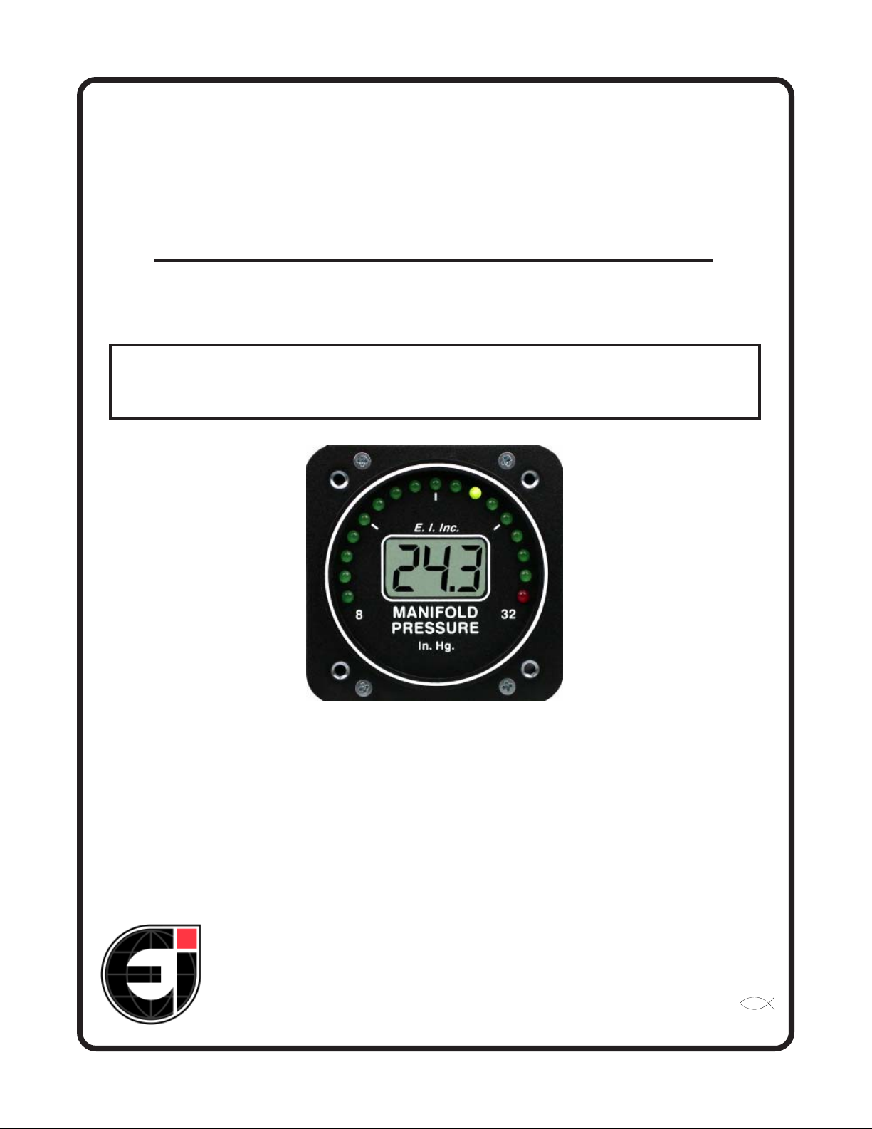
Manifold Pressure (M-1)
Manifold Pressure (M-1)Manifold Pressure (M-1)
(Primary Replacement Instrument)(Primary Replacement Instrument)
(Primary Replacement Instrument)
(Primary Replacement Instrument)(Primary Replacement Instrument)
Operating and Installation InstructionsOperating and Installation Instructions
Operating and Installation Instructions
Operating and Installation InstructionsOperating and Installation Instructions
OI 0517912
Rev. C: 9/30/97
You must read this manual before installing or operating the instrument. This
manual contains warranty and other information that may affect your decision
to install this product and/or the safety of your aircraft.
5/17/91
S/N:S/N:
S/N:
S/N:S/N:
Electronics International Inc. Electronics International Inc.
Electronics International Inc.
Electronics International Inc. Electronics International Inc.
63296 Powell Butte Hwy • Bend, OR 97701 • (541) 318-6060 • Buy-EI.com 63296 Powell Butte Hwy • Bend, OR 97701 • (541) 318-6060 • Buy-EI.com
63296 Powell Butte Hwy • Bend, OR 97701 • (541) 318-6060 • Buy-EI.com
63296 Powell Butte Hwy • Bend, OR 97701 • (541) 318-6060 • Buy-EI.com 63296 Powell Butte Hwy • Bend, OR 97701 • (541) 318-6060 • Buy-EI.com
®®
®
®®
Page 2

Page 3
Important NoticeImportant Notice
Important Notice
Important NoticeImportant Notice
***** MUST READ ********** MUST READ *****
***** MUST READ *****
***** MUST READ ********** MUST READ *****
If you think it is not important to read this manual, you're wrong!If you think it is not important to read this manual, you're wrong!
If you think it is not important to read this manual, you're wrong!
If you think it is not important to read this manual, you're wrong!If you think it is not important to read this manual, you're wrong!
contains important installation information that may affect the safety of your air-contains important installation information that may affect the safety of your air-
contains important installation information that may affect the safety of your air-
contains important installation information that may affect the safety of your air-contains important installation information that may affect the safety of your aircraft, delay your installation or affect the operation of your instrument. You craft, delay your installation or affect the operation of your instrument. You
craft, delay your installation or affect the operation of your instrument. You
craft, delay your installation or affect the operation of your instrument. You craft, delay your installation or affect the operation of your instrument. You
read this manual prior to installing your instrument. read this manual prior to installing your instrument.
read this manual prior to installing your instrument.
read this manual prior to installing your instrument. read this manual prior to installing your instrument.
installation instructions is the sole responsibility of the installer/pilot and mayinstallation instructions is the sole responsibility of the installer/pilot and may
installation instructions is the sole responsibility of the installer/pilot and may
installation instructions is the sole responsibility of the installer/pilot and mayinstallation instructions is the sole responsibility of the installer/pilot and may
render the STC invalid.render the STC invalid.
render the STC invalid.
render the STC invalid.render the STC invalid.
Read the Warranty / AgreementRead the Warranty / Agreement
Read the Warranty / Agreement. There is information in the Warranty / Agreement that may alter
Read the Warranty / AgreementRead the Warranty / Agreement
your decision to install this product.
install this productinstall this product
install this product. This product may be returned for a refund. Contact Electronics International inc. for
install this productinstall this product
details.
Check that the instrument make and model marked on the side of the instrument and on the invoice are
correct before starting the installation.
Check that the limit information on this instrument matches the published limits in your aircraft's
P.O.H. or Flight Manual. Also, this information may be listed in the T.C. Data Sheet for your aircraft. Any
AD's and/or STC's may set forth additional limitations on the operation of your engine. The limit information listed in the AML is for unmodified aircraft and is intended for reference only.
owner's and/or installer's responsibility to determine proper instrument calibration and range markingsowner's and/or installer's responsibility to determine proper instrument calibration and range markings
owner's and/or installer's responsibility to determine proper instrument calibration and range markings
owner's and/or installer's responsibility to determine proper instrument calibration and range markingsowner's and/or installer's responsibility to determine proper instrument calibration and range markings
for your aircraft.for your aircraft.
for your aircraft.
for your aircraft.for your aircraft.
If you do not accept the terms of the Warranty / Agreement, do notIf you do not accept the terms of the Warranty / Agreement, do not
If you do not accept the terms of the Warranty / Agreement, do not
If you do not accept the terms of the Warranty / Agreement, do notIf you do not accept the terms of the Warranty / Agreement, do not
Any deviation from theseAny deviation from these
Any deviation from these
Any deviation from theseAny deviation from these
This manual This manual
This manual
This manual This manual
It is the aircraftIt is the aircraft
It is the aircraft
It is the aircraftIt is the aircraft
MustMust
Must
MustMust
On the front of this instrument you will find a red light marked with the maximum manifold pressure
information. If there are any additional red or yellow lights on this instrument, the operating range of these
lights can be found on a sticker located on the side of the instrument (see the AML at the back of this
manual to decode this information). This instrument designates any "Caution Range" with yellow LEDs,
any "Maximum and Minimum Limits" with Red LEDs and the "Safe Operating Range" with green LEDs.
The "Safe Operating Range" on this instrument is equivalent to the green "Normal Operating Range" and
any unmarked areas on a analog gauge.
It is possible for any instrument to fail thereby displaying inaccurate high, low or jumpy readings.
Therefore, you must be able to recognize an instrument failure and you must be proficient in operating your
aircraft safely in spite of an instrument failure. If you do not have this knowledge, contact the FAA or a
local flight instructor for training.
The pilot
to operate the aircraft that does not know the operation of this product.
aircraft at all times.aircraft at all times.
aircraft at all times.
aircraft at all times.aircraft at all times.
must must
must understand the operation of this product before flying the aircraft. Do not allow anyone
must must
Keep the Operating Manual in theKeep the Operating Manual in the
Keep the Operating Manual in the
Keep the Operating Manual in theKeep the Operating Manual in the
Rev. C: 9/30/97*
Page 4

Page 5

ContentsContents
Contents
ContentsContents
Warranty.............................................................................Warranty.............................................................................
Warranty.............................................................................
Warranty.............................................................................Warranty.............................................................................
Operation Instructions ........................................................Operation Instructions ........................................................
Operation Instructions ........................................................
Operation Instructions ........................................................Operation Instructions ........................................................
Instrument: ............................................................................... 3
Analog Display: ......................................................................... 3
Digital Display: .......................................................................... 3
Installation Instructions .......................................................Installation Instructions .......................................................
Installation Instructions .......................................................
Installation Instructions .......................................................Installation Instructions .......................................................
Important Information and Initial Check Out: ............................. 4
Route The Circular Connector: .................................................. 5
Route the Power and Ground Wires: .......................................... 5
Route the Backlight Wires: ........................................................ 5
Route the (Optional) External Warning Control Line: .................. 6
Install the Instrument in the Panel: ............................................ 6
Connect the Circular Connector to the Instrument: .................... 6
Connect the Manifold Pressure Line: ......................................... 6
Check Instrument Operation: .................................................... 7
Wiring Diagram .................................................................Wiring Diagram .................................................................
Wiring Diagram .................................................................
Wiring Diagram .................................................................Wiring Diagram .................................................................
22
2
22
33
3
33
44
4
44
88
8
88
M-1 Circular Connector ......................................................M-1 Circular Connector ......................................................
M-1 Circular Connector ......................................................
M-1 Circular Connector ......................................................M-1 Circular Connector ......................................................
Specifications and Operating Features ..................................Specifications and Operating Features ..................................
Specifications and Operating Features ..................................
Specifications and Operating Features ..................................Specifications and Operating Features ..................................
STC Information ................................................................STC Information ................................................................
STC Information ................................................................
STC Information ................................................................STC Information ................................................................
1
99
9
99
1010
10
1010
1111
11
1111
Page 6

WW
arranty / Agreementarranty / Agreement
W
arranty / Agreement
WW
arranty / Agreementarranty / Agreement
Electronics International Inc. warrants this instrument and system components to be free from defects in
materials and workmanship for a period of one year from the user invoice date. Electronics International Inc. will repair or replace any item under the terms of this Warranty provided the item is returned
to the factory prepaid.
1. This Warranty shall not apply to any product that has been repaired or altered by any person other
than Electronics International Inc., or that has been subjected to misuse, accident, incorrect wiring,
This warrantyThis warranty
negligence, improper or unprofessional assembly or improper installation by any person.
does not cover any reimbursement for any person’s time for installation, removal, assembly or repair.does not cover any reimbursement for any person’s time for installation, removal, assembly or repair.
does not cover any reimbursement for any person’s time for installation, removal, assembly or repair.
does not cover any reimbursement for any person’s time for installation, removal, assembly or repair.does not cover any reimbursement for any person’s time for installation, removal, assembly or repair.
Electronics International retains the right to determine the reason or cause for warranty repair.
2. This warranty does not extend to any machine, vehicle, boat, aircraft or any other device to which the
Electronics International Inc. product may be connected, attached, interconnected or used in conjunction
with in any way.
3. The obligation assumed by Electronics International Inc. under this warranty is limited to repair,
replacement or refund of the product, at the sole discretion of Electronics International Inc.
4. Electronics International Inc. is not liable for expenses incurred by the customer or installer due to
factory updates, modifications, improvements, upgrades, changes, or any other alterations to the product
that may affect the form, fit, function or operation of the product.
This warranty
This warrantyThis warranty
5. Personal injury or property damage do to misinterpretation or lack of understanding this product is solely the
pilots responsibility. The pilot
allow anyone to operate the aircraft that does not know the operation of this product. Keep the Operating Manual
in the aircraft at all times.
6. E. I. Inc. is not responsible for shipping charges or damages incurred under this Warranty.
7. No representative is authorized to assume any other liability for Electronics International Inc. in
connection with the sale of Electronics International Inc. products.
If you do not agree to and accept the terms of this warranty, you may return the product for aIf you do not agree to and accept the terms of this warranty, you may return the product for a
8.
If you do not agree to and accept the terms of this warranty, you may return the product for a
If you do not agree to and accept the terms of this warranty, you may return the product for aIf you do not agree to and accept the terms of this warranty, you may return the product for a
refund.refund.
refund.
refund.refund.
This Warranty is made only to the original user.
WARRANTIES OR OBLIGATIONS: EXPRESS OR IMPLIED. MANUFACTURER EXPRESSLYWARRANTIES OR OBLIGATIONS: EXPRESS OR IMPLIED. MANUFACTURER EXPRESSLY
WARRANTIES OR OBLIGATIONS: EXPRESS OR IMPLIED. MANUFACTURER EXPRESSLY
WARRANTIES OR OBLIGATIONS: EXPRESS OR IMPLIED. MANUFACTURER EXPRESSLYWARRANTIES OR OBLIGATIONS: EXPRESS OR IMPLIED. MANUFACTURER EXPRESSLY
DISCLAIMS ALL IMPLIED WARRANTIES OF MERCHANTABILITY OR FITNESS FOR ADISCLAIMS ALL IMPLIED WARRANTIES OF MERCHANTABILITY OR FITNESS FOR A
DISCLAIMS ALL IMPLIED WARRANTIES OF MERCHANTABILITY OR FITNESS FOR A
DISCLAIMS ALL IMPLIED WARRANTIES OF MERCHANTABILITY OR FITNESS FOR ADISCLAIMS ALL IMPLIED WARRANTIES OF MERCHANTABILITY OR FITNESS FOR A
PARTICULAR PURPOSE. PURCHASER AGREES THAT IN NO EVENT SHALL MANUFAC-PARTICULAR PURPOSE. PURCHASER AGREES THAT IN NO EVENT SHALL MANUFAC-
PARTICULAR PURPOSE. PURCHASER AGREES THAT IN NO EVENT SHALL MANUFAC-
PARTICULAR PURPOSE. PURCHASER AGREES THAT IN NO EVENT SHALL MANUFAC-PARTICULAR PURPOSE. PURCHASER AGREES THAT IN NO EVENT SHALL MANUFACTURER BE LIABLE FOR SPECIAL, INCIDENTAL OR CONSEQUENTIAL DAMAGES, IN-TURER BE LIABLE FOR SPECIAL, INCIDENTAL OR CONSEQUENTIAL DAMAGES, IN-
TURER BE LIABLE FOR SPECIAL, INCIDENTAL OR CONSEQUENTIAL DAMAGES, IN-
TURER BE LIABLE FOR SPECIAL, INCIDENTAL OR CONSEQUENTIAL DAMAGES, IN-TURER BE LIABLE FOR SPECIAL, INCIDENTAL OR CONSEQUENTIAL DAMAGES, INCLUDING LOST PROFITS OR LOSS OF USE OR OTHER ECONOMIC LOSS. EXCEPT ASCLUDING LOST PROFITS OR LOSS OF USE OR OTHER ECONOMIC LOSS. EXCEPT AS
CLUDING LOST PROFITS OR LOSS OF USE OR OTHER ECONOMIC LOSS. EXCEPT AS
CLUDING LOST PROFITS OR LOSS OF USE OR OTHER ECONOMIC LOSS. EXCEPT ASCLUDING LOST PROFITS OR LOSS OF USE OR OTHER ECONOMIC LOSS. EXCEPT AS
EXPRESSLY PROVIDED HEREIN, MANUFACTURER DISCLAIMS ALL OTHER LIABILITYEXPRESSLY PROVIDED HEREIN, MANUFACTURER DISCLAIMS ALL OTHER LIABILITY
EXPRESSLY PROVIDED HEREIN, MANUFACTURER DISCLAIMS ALL OTHER LIABILITY
EXPRESSLY PROVIDED HEREIN, MANUFACTURER DISCLAIMS ALL OTHER LIABILITYEXPRESSLY PROVIDED HEREIN, MANUFACTURER DISCLAIMS ALL OTHER LIABILITY
TO PURCHASER OR ANY OTHER PERSON IN CONNECTION WITH THE USE OR PERFOR-TO PURCHASER OR ANY OTHER PERSON IN CONNECTION WITH THE USE OR PERFOR-
TO PURCHASER OR ANY OTHER PERSON IN CONNECTION WITH THE USE OR PERFOR-
TO PURCHASER OR ANY OTHER PERSON IN CONNECTION WITH THE USE OR PERFOR-TO PURCHASER OR ANY OTHER PERSON IN CONNECTION WITH THE USE OR PERFORMANCE OF MANUFACTURER’S PRODUCTS, INCLUDING SPECIFICALLY LIABILITY INMANCE OF MANUFACTURER’S PRODUCTS, INCLUDING SPECIFICALLY LIABILITY IN
MANCE OF MANUFACTURER’S PRODUCTS, INCLUDING SPECIFICALLY LIABILITY IN
MANCE OF MANUFACTURER’S PRODUCTS, INCLUDING SPECIFICALLY LIABILITY INMANCE OF MANUFACTURER’S PRODUCTS, INCLUDING SPECIFICALLY LIABILITY IN
TORT.TORT.
TORT.
TORT.TORT.
must must
must understand the operation of this product before flying the aircraft. Do not
must must
THIS WARRANTY IS IN LIEU OF ALL OTHERTHIS WARRANTY IS IN LIEU OF ALL OTHER
THIS WARRANTY IS IN LIEU OF ALL OTHER
THIS WARRANTY IS IN LIEU OF ALL OTHERTHIS WARRANTY IS IN LIEU OF ALL OTHER
2
Page 7

Operation InstructionsOperation Instructions
Operation Instructions
Operation InstructionsOperation Instructions
M-1M-1
M-1
M-1M-1
0517932
Instrument:Instrument:
Instrument:
Instrument:Instrument:
The M-1 is a precision manifold pressure instrument featuring a 210 degree analog display and a digital
display. These two displays have many advantages over conventional analog gauges as described below.
Also, the M-1 features long-term accuracy and reliability. Since the M-1 does not incorporate any moving
parts (needles, bearings, springs, etc.) there is little to go wrong or wear out. The internal microprocessor assures
accuracy and repeatability.
Analog Display:Analog Display:
Analog Display:
Analog Display:Analog Display:
The 210 degree analog display provides a quick reference of manifold pressure with respect to its operating
range. At a glance you can get a relative idea of where in the range you are operating the engine and how close to
the maximum limit you are. Precise information is provided in the digital display.
An advantage of the analog display is its ability to emit a green, yellow or red light. With a quick glance you
can determine if you’re operating in a normal, caution or restricted range. Also, when you exceed a maximum
limit the red light will blink 20 times at full intensity to catch your attention and warn you that a maximum limit
has been violated. After 20 blinks the red light will stop blinking and display continuous red so it does not distract
you.
During night operation the analog lights may be too bright. If so, turn the panel light rheostat up and the
analog lights will dim. The red (maximum limit) light will always be displayed at full intensity.
Digital Display:Digital Display:
Digital Display:
Digital Display:Digital Display:
The M-1 measures absolute atmospheric pressure in the engine’s manifold to .1 inches of mercury. This
reading should not be confused with barometric pressure. Barometric pressure readings are altitude compensated
to sea level. For every 100 feet above sea level there is approximately .1 inches of mercury less manifold pressure
available to the engine. That means at 1000 feet above sea level with a barometric reading of 30.0 inches of
mercury, the maximum manifold pressure available for a non-turbocharged aircraft is 29.0 inches of mercury.
Less manifold pressure means less power.
Two other factors affecting manifold pressure are induction loss and ram air. Induction loss is the normal
drop in pressure across the carburetor and intake manifold. This will lower your available manifold pressure by
approximately 1.0 inches of mercury. Ram air, on the other hand, will increase your manifold pressure. Ram air
is the normal compression of air in the manifold caused by airspeed and dependent on the location of the intake
air pickup point. At 145 knots the maximum increase in manifold pressure available is 1.0 inches of mercury.
3
Rev. A: 6/16/92
Page 8

The M-1 can detect a change in manifold pressure for every 100 feet of elevation or .1 inches change in
barometric pressure. This allows for precise setting and monitoring of the manifold pressure.
If the digital display backlight has been permanently powered up (as recommended), the digital display will
be easier to see during low ambient light conditions and at night.
Installation InstructionsInstallation Instructions
Installation Instructions
Installation InstructionsInstallation Instructions
M-1M-1
M-1
M-1M-1
Important Information and Initial Check Out:Important Information and Initial Check Out:
Important Information and Initial Check Out:
Important Information and Initial Check Out:Important Information and Initial Check Out:
The installer and aircraft owner must read the Warranty before starting the installation.The installer and aircraft owner must read the Warranty before starting the installation.
1.
The installer and aircraft owner must read the Warranty before starting the installation. There is
The installer and aircraft owner must read the Warranty before starting the installation.The installer and aircraft owner must read the Warranty before starting the installation.
information in the Warranty that may alter your decision to install this instrument.
the terms of the Warranty, do not install this instrument.the terms of the Warranty, do not install this instrument.
the terms of the Warranty, do not install this instrument.
the terms of the Warranty, do not install this instrument.the terms of the Warranty, do not install this instrument.
2. If you are not an FAA Certified Aircraft Mechanic familiar with the issues of installing aircraft mani-2. If you are not an FAA Certified Aircraft Mechanic familiar with the issues of installing aircraft mani-
2. If you are not an FAA Certified Aircraft Mechanic familiar with the issues of installing aircraft mani-
2. If you are not an FAA Certified Aircraft Mechanic familiar with the issues of installing aircraft mani-2. If you are not an FAA Certified Aircraft Mechanic familiar with the issues of installing aircraft manifold pressure instruments, fold pressure instruments,
fold pressure instruments,
fold pressure instruments, fold pressure instruments,
aircraft standards and practices to install this instrument (refer to AC 43.13).aircraft standards and practices to install this instrument (refer to AC 43.13).
aircraft standards and practices to install this instrument (refer to AC 43.13).
aircraft standards and practices to install this instrument (refer to AC 43.13).aircraft standards and practices to install this instrument (refer to AC 43.13).
Do Not attempt to install this instrument.Do Not attempt to install this instrument.
Do Not attempt to install this instrument.
Do Not attempt to install this instrument.Do Not attempt to install this instrument.
The installer should use current The installer should use current
The installer should use current
The installer should use current The installer should use current
If you do not acceptIf you do not accept
If you do not accept
If you do not acceptIf you do not accept
Check that any necessary FAA Approvals (STC's, etc.) are available for your aircraft before startingCheck that any necessary FAA Approvals (STC's, etc.) are available for your aircraft before starting
3.
Check that any necessary FAA Approvals (STC's, etc.) are available for your aircraft before starting
Check that any necessary FAA Approvals (STC's, etc.) are available for your aircraft before startingCheck that any necessary FAA Approvals (STC's, etc.) are available for your aircraft before starting
the installation. The FAA Approved Model List (AML) is located at the back of this manual. the installation. The FAA Approved Model List (AML) is located at the back of this manual.
the installation. The FAA Approved Model List (AML) is located at the back of this manual.
the installation. The FAA Approved Model List (AML) is located at the back of this manual. the installation. The FAA Approved Model List (AML) is located at the back of this manual.
any issues you may have before starting the installation.any issues you may have before starting the installation.
any issues you may have before starting the installation.
any issues you may have before starting the installation.any issues you may have before starting the installation.
4. Before starting the installation, read the entire Installation Instructions and resolve any issues you may
have. This may eliminate any delays once the installation is started.
5. Check that the instrument make and model marked on the side of the instrument and on the invoice are
correct before starting the installation.
6. Check that the limit information on this instrument matches the published limits in your aircraft's P.O.H.
or Flight Manual. Also, this information may be listed in the T.C. Data Sheet for your aircraft. Any AD's
and/or STC's may set forth additional limitations on the operation of your engine. The limit information
listed in the AML is for unmodified aircraft and is intended for reference only.
and/or installer's responsibility to determine proper instrument calibration and range markings for yourand/or installer's responsibility to determine proper instrument calibration and range markings for your
and/or installer's responsibility to determine proper instrument calibration and range markings for your
and/or installer's responsibility to determine proper instrument calibration and range markings for yourand/or installer's responsibility to determine proper instrument calibration and range markings for your
aircraft.aircraft.
aircraft.
aircraft.aircraft.
On the front of this instrument you will find a red light marked with the maximum manifold pressure
information. If there are any additional red or yellow lights on this instrument, the operating range of
these lights can be found on a sticker located on the side of the instrument (see the AML at the back of
this manual to decode this information). This instrument designates any "Caution Range" with yellow
LEDs, any "Maximum and Minimum Limits" with Red LEDs and the "Safe Operating Range" with green
LEDs. The "Safe Operating Range" on this instrument is equivalent to the green "Normal Operating
Range" and any unmarked areas on a analog gauge.
It is the aircraft owner'sIt is the aircraft owner's
It is the aircraft owner's
It is the aircraft owner'sIt is the aircraft owner's
ResolveResolve
Resolve
ResolveResolve
4
Rev. C: 9/30/97
Page 9

Do not attempt to remove or replace the limit stickers on this instrument. If the manifold pressure limits
for your engine do not match those which are marked on this instrument send this unit back to Electronics
International Inc. for recalibration.
erly calibrated for your aircraft.
7. Before starting the installation make sure the unit will fit in the location you intend to install it without
obstructing the operation of any controls.
8. If this instrument is to replace an existing unit in the aircraft, it is the installer's responsibility to move or
replace any existing instruments or components in accordance with FAA approved methods and procedures. The following Installation Instructions do not cover moving or the removal of any existing instruments or components.
Route The Circular Connector:Route The Circular Connector:
Route The Circular Connector:
Route The Circular Connector:Route The Circular Connector:
Starting from under the instrument panel, route the circular connector wire harness up to the instrument
mounting location. (See the wiring diagram at the back of this manual). Place the circular connector about 8
inches back from the panel. Tie wrap the harness in place approximately 1 foot back from the circular connector.
This will allow the harness to be flexible and accomodate varying lengths in instrument wires.
wires do not obstruct the freedom of travel of any controls.wires do not obstruct the freedom of travel of any controls.
wires do not obstruct the freedom of travel of any controls.
wires do not obstruct the freedom of travel of any controls.wires do not obstruct the freedom of travel of any controls.
DO NOT install or use a primary engine instrument that is not prop-
Be sure theseBe sure these
Be sure these
Be sure theseBe sure these
Route the Power and Ground Wires:Route the Power and Ground Wires:
Route the Power and Ground Wires:
Route the Power and Ground Wires:Route the Power and Ground Wires:
Route the red wire in the harness to the aircraft’s 12 or 24 volt main or emergency bus as applicable via an
independent circuit breaker (five amps or less). An alternate method would be to route the red lead to the bus via
a one amp in-line fuse. With this method a spare fuse should be kept in the aircraft.
Route the black wire in the harness to a good ground .
freedom of travel of any controls.freedom of travel of any controls.
freedom of travel of any controls.
freedom of travel of any controls.freedom of travel of any controls.
Route the Backlight Wires:Route the Backlight Wires:
Route the Backlight Wires:
Route the Backlight Wires:Route the Backlight Wires:
Connect the backlight wires as follows:
1. It is recommended to permanently power up the digital display backlight.
a) For a 12-volt system connect the white/brown wire to the instrument Red Power Lead. Connect the white/red wire to ground (see Wiring Diagram).
b) For a 24-volt system leave the white/brown open. Connect the white/red wire to the instrument
Red Power Lead (see Wiring Diagram).
Tie wrap these wires so they do not obstruct theTie wrap these wires so they do not obstruct the
Tie wrap these wires so they do not obstruct the
Tie wrap these wires so they do not obstruct theTie wrap these wires so they do not obstruct the
2. Connect the white/orange wire to the panel light rheostat. This wire will dim the analog LED’s for
night operation when the panel lights are turned on. If this line is left open, the analog LED's will
remain at full intensity at all times. Also, if the voltage on this line drops below 11.5 volts, the analog
LED's will be displayed at full intensity.
travel of any controls.travel of any controls.
travel of any controls.
travel of any controls.travel of any controls.
Tie wrap all wires so they do not obstruct the freedom ofTie wrap all wires so they do not obstruct the freedom of
Tie wrap all wires so they do not obstruct the freedom of
Tie wrap all wires so they do not obstruct the freedom ofTie wrap all wires so they do not obstruct the freedom of
5
Rev. C: 9/30/97
Page 10

Route the (Optional) External Warning Control Line:Route the (Optional) External Warning Control Line:
Route the (Optional) External Warning Control Line:
Route the (Optional) External Warning Control Line:Route the (Optional) External Warning Control Line:
The white/yellow wire can be connected to an external light (AL-1), buzzer (ATG-1), voice annunciator (AV-
17), a relay, etc. This wire grounds when the red warning light is on. The current in this line must be limited to 2/
10 of an amp maximum. Exceeding this limit will damage the unit. If this feature is not used, leave this line
Tie wrap this wire so it does not obstruct the freedom of travel of any controls.Tie wrap this wire so it does not obstruct the freedom of travel of any controls.
open.
Install the Instrument in the Panel:Install the Instrument in the Panel:
Install the Instrument in the Panel:
Install the Instrument in the Panel:Install the Instrument in the Panel:
longer than 1/2".
Connect the Circular Connector to the Instrument:Connect the Circular Connector to the Instrument:
Connect the Circular Connector to the Instrument:
Connect the Circular Connector to the Instrument:Connect the Circular Connector to the Instrument:
Connect the Manifold Pressure Line:Connect the Manifold Pressure Line:
Connect the Manifold Pressure Line:
Connect the Manifold Pressure Line:Connect the Manifold Pressure Line:
Tie wrap this wire so it does not obstruct the freedom of travel of any controls.
Tie wrap this wire so it does not obstruct the freedom of travel of any controls.Tie wrap this wire so it does not obstruct the freedom of travel of any controls.
Install the instrument from behind the instrument panel using 6 x 32 screws. These screws should not be any
1) Push the two mating connectors together and twist them until they snap into position.
2) Turn the locking ring on the instrument connector clockwise (1 1/2 turns) until it locks into position.
Connect the aircraft manifold pressure line to the pressure port on the back of the instrument. Be sure this
line is tight. This pressure port is a 1/4" flare union and is standard for most manifold pressure gauges. Care
should be taken not to put excess pressure on the flexible line between the flare union and the pressure transducer
mounted on the back of the instrument. The Pressure Transducer Port can break.
sure line does not have any kinks.sure line does not have any kinks.
sure line does not have any kinks.
sure line does not have any kinks.sure line does not have any kinks.
Pressure Transducer.
.170 ID Flexible Line.
Pressure Port.
Back of Unit.
NoteNote
: :
Note
: Some aircraft have a very small hole in the maniflold pressure line to create an airflow in the line. This
NoteNote
: :
small flow of air keeps fuel from working its way into the manifold pressure gauge or tranducer whitch can cause
damage over time.
Make sure the flexible pres-Make sure the flexible pres-
Make sure the flexible pres-
Make sure the flexible pres-Make sure the flexible pres-
Aircraft Manifold Pressure
Line.
6
Rev. C: 9/30/97
Page 11

Check Instrument Operation:Check Instrument Operation:
Check Instrument Operation:
Check Instrument Operation:Check Instrument Operation:
Check instrument operation as follows:
1. Turn the master switch on (engine off) and verify that the instrument sequences through all the analog
lights and reads approximately barometric pressure less .1 inches of mercury for every 100 feet you are
above sea level. A problem at this step could be caused by poor connections on the red and/or black leads.
2. Check the digital display backlight. With high or medium ambient light it is hard to see the digital display
backlight (it is only required during low ambient light conditions but should be on all the time).
3. Start the aircraft engine and check the digital and analog display to read properly. A problem at this step
could be caused by a restriction or leak in the manifold pressure line.
M-1 connected.M-1 connected.
M-1 connected. This will damage the pressure transducer.
M-1 connected.M-1 connected.
Never pressurize this line with theNever pressurize this line with the
Never pressurize this line with the
Never pressurize this line with theNever pressurize this line with the
7
Rev. A: 6/16/92
Page 12

Manifold Pressure (M-1)Manifold Pressure (M-1)
Manifold Pressure (M-1)
Manifold Pressure (M-1)Manifold Pressure (M-1)
Wiring Diagram Wiring Diagram
Wiring Diagram
Wiring Diagram Wiring Diagram
WD 0313911
Do not use screws longer
than 1/2" (4 ea.).
Aircraft Manifold Pressure Line.
Pressure Port.
Circular Connector
Red
Black
White/
Brwn
White/Red
Wire Harness
White/
Orng
White/Yel
Power Lead, connects to 12 or 24 Volt Bus via one amp fuse.
Ground Lead, connects to Ground.
12V Backlight Control Line, connects to Red Power Lead for 12V system.
12 volts turns on the digital display backlight.
24V Backlight Control Line, connects to Red Power Lead for 24V
system.
Analog LED Lighting Control Line, connects to Panel Light Rheostat.
12/24 volts dims the analog LEDs.
(Optional) External Warning Control Line. Can be connected to a relay
to control an external light, buzzer, etc. Grounds when Red Warning
Light is on. Current must be limited to 2/10 amp maximum.
Connects to ground for 12 Volt System.Connects to ground for 12 Volt System.
Connects to ground for 12 Volt System.
Connects to ground for 12 Volt System.Connects to ground for 12 Volt System.
8
Rev. A: 6/16/92
Page 13

M-1 Circular ConnectorM-1 Circular Connector
M-1 Circular Connector
M-1 Circular ConnectorM-1 Circular Connector
Connecting Cable Harness, Back View (wire side)
OR
Instrument Connector, Front View
W/
3
Yel
W/
6
OrgW/RedW/Brn
9
Blk
Red
1
4
7
Note: See Wiring Diagram for
hook up information.
9
Rev. A: 6/16/92
Page 14

Specifications and Operating FeaturesSpecifications and Operating Features
Specifications and Operating Features
Specifications and Operating FeaturesSpecifications and Operating Features
S0515911
Model:
M-1 (Manifold Pressure Instrument)
Case Dimensions:
2.5" x 2.5" x 3.65" depth, 2 1/4" Bezel.
Weight:
13 Oz.
Environmental:
Meets TSO C45.
Power Requirements:
7.5 to 30 Volts, 1/10 Amp.
Analog Display:
17 High Intensity Light Emitting Diodes (LEDs) in a 210 degree arc with Intensity Control Line available for
dimming. Sequential flash test on power up. Microprocessor eliminates LED hunting (flicker).
5/15/91
Red LEDs:
If the Analog Display goes from a Green LED or Yellow LED to a Red LED, the Red LED will blink 20
times then go solid red.
Digital Display:
LCD (viewable in direct sunlight), with 12 and 24 volt backlight control wires for night operation. Displays
“888” on power up.
Accuracy:
1% in accordance with TSO C45.
Resolution:
.1 In. Hg.
Max Range:
Max Allowable: 60 In. Hg. for standard unit.
Max Allowable: 120 In. Hg. for units with requirments over 45 In. Hg.
Update Time:
3 times per second.
Pressure Port:
1/4 inch male flare union mounted on a .170 I.D. flexible tube located on the back of the unit.
External Warning Control Line:
Grounds when any Red Warning Light is on or blinking. Current should be limited to 2/10 amp.
10
Rev. C: 9/30/97
 Loading...