

Page 1

Page 2

Important Notice
***** MUST READ *****
Page 1 of 4
If you think it is not important to read this manual, you’re wrong! This manual
contains important operating information that may affect the safety of you, your
aircraft and passengers.
Read the Warranty / AgreementRead the Warranty / Agreement
Read the Warranty / Agreement. There is information in the Warranty/Agreement that may alter your
Read the Warranty / AgreementRead the Warranty / Agreement
decision to install this product.
not install this productnot install this product
not install this product. This product may be returned for a refund. Contact Electronics International
not install this productnot install this product
inc. for details.
By installing this product, the aircraft owner/pilot and installer agree to hold Electronics International Inc.
harmless and in no way responsible for monetary compensation, including punitive damages for any
incident, harm and/or damage associated with this product. If you do not agree to the above,
INSTALL THIS PRODUCT.INSTALL THIS PRODUCT.
INSTALL THIS PRODUCT. This product may be returned for a refund. Contact Electronics Interna-
INSTALL THIS PRODUCT.INSTALL THIS PRODUCT.
tional inc. for details.
If you do not accept the terms of the Warranty / Agreement, doIf you do not accept the terms of the Warranty / Agreement, do
If you do not accept the terms of the Warranty / Agreement, do
If you do not accept the terms of the Warranty / Agreement, doIf you do not accept the terms of the Warranty / Agreement, do
DO NOTDO NOT
DO NOT
DO NOTDO NOT
mustmust
The pilot
allow anyone to operate the aircraft that does not know how to properly interpret and operate this product.
Keep the Operating Instructions in the aircraft at all times. If you do not thoroughly understand the
operation of this product, contact a knowledgeable flight instructor for training.
The ability for this product to respond to an engine or aircraft system anomaly is directly related to how
that anomaly affects the reading of the function(s) being monitored (i.e.; if an engine fire does not affect
the EGT or CHT, the EGT and CHT readings will not change).
This instrument only displays the parameters for the function(s) being monitored. The pilot is responsible
for interpreting the data and determining if an engine or aircraft system anomaly exists. When using this
instrument, the pilot’s diagnostic ability is limited to his/her interpretation of the displayed data and the
their observation skills. To improve these skills the pilot should seek training from a flight instructor.
If after reading this manual you do not have the knowledge to interpret the displayed data to operate the
aircraft safely or to detect engine and/or aircraft system problems, contact a knowledgeable instructor for
training prior to flying the aircraft with this instrument.
If you detect a problem using this instrument, it is your responsibility to take appropriate action to ensure
the safety of the flight. Practice simulating problems to build your skills and to improve your understand
of the relationships between problems and their affects on the displayed data. To ensure you are taking
appropriate action, contact a knowledgeable flight instructor for training. Inappropriate action can lead to
aircraft and/or engine damage, personal injury or death.
must
understand the operation and limitations of this product before flying the aircraft. Do not
mustmust
This manual does not make any recommendations as to specific operating parameters or controlling
methods. Check the airframe and/or engine manufacturer’s recommendations to properly operate the
aircraft systems and engine. It is the pilot’s responsibility to operate the engine and aircraft safely.
Page 3

Important Notice
***** MUST READ *****
Page 2 of 4
It is possible for any instrument to fail thereby displaying inaccurate high, low or jumpy readings.
Therefore, you
your aircraft safely in spite of an instrument failure. If you do not have this knowledge, contact the FAA
or a knowledgeable flight instructor for training prior to flying the aircraft with this instrument.
Electronics International Inc. is not liable or responsible for a pilot’s action or any situation that results in
personal injury, property damage, missed commitments, lack of use of an aircraft or any expenses
incurred due to: product failure, inaccuracy in displayed data or text files, display or display format
issues, software bugs or problems, upgrade or customization issues, misinterpretation of the display,
warning and/or limit settings, calibration problems, installation issues (leaks, mis-wiring, obstructions,
damage to aircraft or components, incorrect installation of any parts, wrong parts, parts that don’t fit,
etc.) or any other issues related to the installation or operation of this product. All of the above are
solely the pilot’s and/or installer’s responsibility. The pilot
uct before flying the aircraft. The pilot must not allow anyone to operate the aircraft that does not know
the operation of this product. The pilot must keep the instrument Operating Instructions in the aircraft at
all times.
mustmust
must be able to recognize an instrument failure and you
mustmust
mustmust
must
understand the operation of this prod-
mustmust
mustmust
must be proficient in operating
mustmust
Set a unique password to protect all of the calibration and setup data in the CGR-30P. If setup or calibration data is inadvertently or improperly changed, you could get inaccurate readings that may lead to
improper operation of the aircraft or engine. This could result in engine damage and/or an emergency
situation.
Before flying the aircraft verify that the instrument markings displayed on the CGR are accurate with
your POH for every function displayed on the CGR.
The CGR must be calibrated to the aircraft fuel system and the CGR's accuracy must be verified before
flying the aircraft.
Fuel Level Accuracy Limitations:Fuel Level Accuracy Limitations:
Fuel Level Accuracy Limitations:
Fuel Level Accuracy Limitations:Fuel Level Accuracy Limitations:
The accuracy limitations of the CGR are listed below.
anyone flying the aircraft aware of these limitations.anyone flying the aircraft aware of these limitations.
anyone flying the aircraft aware of these limitations.
anyone flying the aircraft aware of these limitations.anyone flying the aircraft aware of these limitations.
1. Angle of Attack -1. Angle of Attack -
1. Angle of Attack - The CGR must be calibrated with the aircraft in a cruise angle of attack. If the
1. Angle of Attack -1. Angle of Attack aircraft is in an angle of attack other than cruise, the CGR may display inaccurate fuel levels (depending
on the mounting location and type of sensor used). If your aircraft does not sit at a cruise angle of attack
when on the ground, it may not display accurate fuel levels.
of attack to determine how the CGR fuel level readings are affected.of attack to determine how the CGR fuel level readings are affected.
of attack to determine how the CGR fuel level readings are affected.
of attack to determine how the CGR fuel level readings are affected.of attack to determine how the CGR fuel level readings are affected.
It is the pilot/owner’s obligation to makeIt is the pilot/owner’s obligation to make
It is the pilot/owner’s obligation to make
It is the pilot/owner’s obligation to makeIt is the pilot/owner’s obligation to make
Test your aircraft at different anglesTest your aircraft at different angles
Test your aircraft at different angles
Test your aircraft at different anglesTest your aircraft at different angles
Full Fuel Readings -Full Fuel Readings -
2.
Full Fuel Readings - As a tank is filled the fuel sensor may be unable to detect the fuel entering
Full Fuel Readings -Full Fuel Readings -
Page 4

Important Notice
***** MUST READ *****
Page 3 of 4
the upper corners of the fuel tank. If this is the case with your sensor, the CGR may display fuel levels
lower than the actual fuel in the tanks when the tanks are full. When the fuel level drops to a point
where the fuel sensor starts to detect a change, the displayed fuel level should be accurate.
accuracy of your system by comparing the displayed fuel levels on the CGR to the fuelaccuracy of your system by comparing the displayed fuel levels on the CGR to the fuel
accuracy of your system by comparing the displayed fuel levels on the CGR to the fuel
accuracy of your system by comparing the displayed fuel levels on the CGR to the fuelaccuracy of your system by comparing the displayed fuel levels on the CGR to the fuel
levels listed in the flight manual at each fill up.levels listed in the flight manual at each fill up.
levels listed in the flight manual at each fill up.
levels listed in the flight manual at each fill up.levels listed in the flight manual at each fill up.
Check the Check the
Check the
Check the Check the
3. Low Fuel Readings -3. Low Fuel Readings -
3. Low Fuel Readings -
3. Low Fuel Readings -3. Low Fuel Readings for an indicated tank level below 1/8for an indicated tank level below 1/8
for an indicated tank level below 1/8. You should always fly the aircraft in such a manner as to
for an indicated tank level below 1/8for an indicated tank level below 1/8
at least maintain the FAA minimum fuel requirements in the aircraft at all times.
mounting location and type of fuel sensor used, the CGR may not be able to accuratelymounting location and type of fuel sensor used, the CGR may not be able to accurately
mounting location and type of fuel sensor used, the CGR may not be able to accurately
mounting location and type of fuel sensor used, the CGR may not be able to accuratelymounting location and type of fuel sensor used, the CGR may not be able to accurately
measure the last few gallons of fuel in the tanks.measure the last few gallons of fuel in the tanks.
measure the last few gallons of fuel in the tanks.
measure the last few gallons of fuel in the tanks.measure the last few gallons of fuel in the tanks.
4. Improper Calibration -4. Improper Calibration -
4. Improper Calibration - If the CGR has not been properly calibrated, it will not display accurate
4. Improper Calibration -4. Improper Calibration fuel levels in the tanks. It is important to verify the accuracy of the CGR.
measured fuel levels in the tanks with the readings on the CGR before each flight.measured fuel levels in the tanks with the readings on the CGR before each flight.
measured fuel levels in the tanks with the readings on the CGR before each flight.
measured fuel levels in the tanks with the readings on the CGR before each flight.measured fuel levels in the tanks with the readings on the CGR before each flight.
5. Poor Connections -5. Poor Connections -
5. Poor Connections - Poor connections between the wires leading from the EDC to the fuel
5. Poor Connections -5. Poor Connections sensors can become intermittent with age. An intermittent connection most likely will show up as
wandering or inaccurate readings on the CGR.
in the tanks with the readings on the CGR before each flight.in the tanks with the readings on the CGR before each flight.
in the tanks with the readings on the CGR before each flight.
in the tanks with the readings on the CGR before each flight.in the tanks with the readings on the CGR before each flight.
6. Defective Fuel Level Sensors -6. Defective Fuel Level Sensors -
6. Defective Fuel Level Sensors - Fuel sensors can become intermittent or change resistance
6. Defective Fuel Level Sensors -6. Defective Fuel Level Sensors with age. It is not uncommon to find intermittent problems even in new resistive sensors. An intermittent problem with a fuel sensor most likely will show up as wandering or inaccurate readings on the
CGR.
CGR at each fill up.CGR at each fill up.
CGR at each fill up.
CGR at each fill up.CGR at each fill up.
Always cross check the measured fuel levels in the tanks with the readings on theAlways cross check the measured fuel levels in the tanks with the readings on the
Always cross check the measured fuel levels in the tanks with the readings on the
Always cross check the measured fuel levels in the tanks with the readings on theAlways cross check the measured fuel levels in the tanks with the readings on the
Do not rely on the CGR to determine the fuel level in the tankDo not rely on the CGR to determine the fuel level in the tank
Do not rely on the CGR to determine the fuel level in the tank
Do not rely on the CGR to determine the fuel level in the tankDo not rely on the CGR to determine the fuel level in the tank
Depending on theDepending on the
Depending on the
Depending on theDepending on the
Always cross check yourAlways cross check your
Always cross check your
Always cross check yourAlways cross check your
Always cross check your measured fuel levelsAlways cross check your measured fuel levels
Always cross check your measured fuel levels
Always cross check your measured fuel levelsAlways cross check your measured fuel levels
Page 5

Important Notice
***** MUST READ *****
Page 4 of 4
Important Fuel Level Considerations:Important Fuel Level Considerations:
Important Fuel Level Considerations:
Important Fuel Level Considerations:Important Fuel Level Considerations:
DO NOT RELY SOLELY ON THE FUEL LEVEL DISPLAYED ON THE CGR TODO NOT RELY SOLELY ON THE FUEL LEVEL DISPLAYED ON THE CGR TO
DO NOT RELY SOLELY ON THE FUEL LEVEL DISPLAYED ON THE CGR TO
DO NOT RELY SOLELY ON THE FUEL LEVEL DISPLAYED ON THE CGR TODO NOT RELY SOLELY ON THE FUEL LEVEL DISPLAYED ON THE CGR TO
DETERMINE THE FUEL LEVELS IN THE AIRCRAFT.DETERMINE THE FUEL LEVELS IN THE AIRCRAFT.
DETERMINE THE FUEL LEVELS IN THE AIRCRAFT.
DETERMINE THE FUEL LEVELS IN THE AIRCRAFT.DETERMINE THE FUEL LEVELS IN THE AIRCRAFT.
eliminate or reduce the necessity for the pilot to use good flight planning, preflight andeliminate or reduce the necessity for the pilot to use good flight planning, preflight and
eliminate or reduce the necessity for the pilot to use good flight planning, preflight and
eliminate or reduce the necessity for the pilot to use good flight planning, preflight andeliminate or reduce the necessity for the pilot to use good flight planning, preflight and
in-flight techniques for managing fuel.in-flight techniques for managing fuel.
in-flight techniques for managing fuel. It is important the pilot adopt the practices listed below.
in-flight techniques for managing fuel.in-flight techniques for managing fuel.
If you are not familiar with these techniques, contact the FAA to acquire proper training.
1. 1.
A copy of these Operating Instructions must be in the aircraft at all times.A copy of these Operating Instructions must be in the aircraft at all times.
1.
A copy of these Operating Instructions must be in the aircraft at all times.
1. 1.
A copy of these Operating Instructions must be in the aircraft at all times.A copy of these Operating Instructions must be in the aircraft at all times.
2. Flight Planning -2. Flight Planning -
2. Flight Planning - Always calculate the fuel requirement for each leg of a flight, including any
2. Flight Planning -2. Flight Planning alternate plans for bad weather or other problems. Keep this information available in the aircraft
during the flight. Keep a chart of the published fuel flows for various flight/engine conditions in the
aircraft. Keep a chart of the measured fuel flows for various flights in the aircraft. Measured fuel
flows can be considerably different from published figures.
The use of the CGR does not The use of the CGR does not
The use of the CGR does not
The use of the CGR does not The use of the CGR does not
3. Preflight - Do not rely on the CGR to determine the fuel level in the fuel tanks. The3. Preflight - Do not rely on the CGR to determine the fuel level in the fuel tanks. The
3. Preflight - Do not rely on the CGR to determine the fuel level in the fuel tanks. The
3. Preflight - Do not rely on the CGR to determine the fuel level in the fuel tanks. The3. Preflight - Do not rely on the CGR to determine the fuel level in the fuel tanks. The
pilot must visually check/measure the fuel levels in the tanks before every takeoff.pilot must visually check/measure the fuel levels in the tanks before every takeoff.
pilot must visually check/measure the fuel levels in the tanks before every takeoff. Cross
pilot must visually check/measure the fuel levels in the tanks before every takeoff.pilot must visually check/measure the fuel levels in the tanks before every takeoff.
check the measured fuel levels with the displayed levels on the CGR. Also, cross check these levels
with the fuel requirements for the flight listed in your flight plan.
4. In Flight -4. In Flight -
4. In Flight - Make the CGR part of your normal instrument scan.
4. In Flight -4. In Flight displayed on the CGR with your flight plan at each leg of the flight or every 30 minutesdisplayed on the CGR with your flight plan at each leg of the flight or every 30 minutes
displayed on the CGR with your flight plan at each leg of the flight or every 30 minutes
displayed on the CGR with your flight plan at each leg of the flight or every 30 minutesdisplayed on the CGR with your flight plan at each leg of the flight or every 30 minutes
(if a leg is longer than 30 minutes). Calculate the fuel flows from the CGR displayed fuel levels and
compare them with your charts of measured and published fuel flows for the aircraft. If there is a
discrepancy, land the aircraft at the nearest airport and verify the fuel levels. Discrepancies should be
taken seriously.
5. New Pilot or Owner of the Aircraft -5. New Pilot or Owner of the Aircraft -
5. New Pilot or Owner of the Aircraft -
5. New Pilot or Owner of the Aircraft -5. New Pilot or Owner of the Aircraft aircraft, it is the previous aircraft pilot/owner’s responsibility to insure the new pilot/aircraft, it is the previous aircraft pilot/owner’s responsibility to insure the new pilot/
aircraft, it is the previous aircraft pilot/owner’s responsibility to insure the new pilot/
aircraft, it is the previous aircraft pilot/owner’s responsibility to insure the new pilot/aircraft, it is the previous aircraft pilot/owner’s responsibility to insure the new pilot/
owner has read this manual and is aware of any accuracy limitations and other importantowner has read this manual and is aware of any accuracy limitations and other important
owner has read this manual and is aware of any accuracy limitations and other important
owner has read this manual and is aware of any accuracy limitations and other importantowner has read this manual and is aware of any accuracy limitations and other important
considerations. All limitations and operating characteristics learned from operating theconsiderations. All limitations and operating characteristics learned from operating the
considerations. All limitations and operating characteristics learned from operating the
considerations. All limitations and operating characteristics learned from operating theconsiderations. All limitations and operating characteristics learned from operating the
CGR must be passed on to the new pilot/owner.CGR must be passed on to the new pilot/owner.
CGR must be passed on to the new pilot/owner.
CGR must be passed on to the new pilot/owner.CGR must be passed on to the new pilot/owner.
If there is a new pilot or new owner of theIf there is a new pilot or new owner of the
If there is a new pilot or new owner of the
If there is a new pilot or new owner of theIf there is a new pilot or new owner of the
Crosscheck the fuel levelsCrosscheck the fuel levels
Crosscheck the fuel levels
Crosscheck the fuel levelsCrosscheck the fuel levels
Page 6

Contents
(Page 1 of 2)
Warranty/Agreement----------------------------------------------------------------------------------------- 1
1.0 Introduction: ---------------------------------------------------------------------------------- 3
1.1 Features ------------------------------------------------------------------------------- 5
1.2 Overview of the CGR Screens: -------------------------------------------------------- 5
1.3 System Hardware: --------------------------------------------------------------------- 6
1.4 SELECT Knob and Button Operation: ------------------------------------------------- 7
1.5 Display Dimming: ---------------------------------------------------------------------- 7
1.6 Cleaning the Screen: ------------------------------------------------------------------- 7
2.0 Main Engine Screen: -------------------------------------------------------------------------- 9
2.1 Power-up Add Fuel Message: --------------------------------------------------------- 11
2.2 Main Screen Layout: ------------------------------------------------------------------- 11
2.3 RPM and Maniflod Pressure: ---------------------------------------------------------- 12
2.4 Horizontal Strip Gauges: --------------------------------------------------------------- 12
2.5 Bar Graph Analyzer: ------------------------------------------------------------------- 12
2.6 Main Screen Annunciators: ------------------------------------------------------------ 15
2.7 External Master Caution and Warning Light: ------------------------------------------- 15
2.8 Voice Alarm Control Panel (OEM Only): ---------------------------------------------- 15
3.0 Secondary Screen: --------------------------------------------------------------------------- 17
3.1 RPM and Mainifold pressure Gauges: ------------------------------------------------- 18
3.2 Three Annunciators: ------------------------------------------------------------------- 18
3.3 Six Horizontal Strip and/or Digital Gauges: --------------------------------------------- 18
3.4 EGT/CHT Digital Gauges: ------------------------------------------------------------- 18
4.0 Fuel Qtys Screens: --------------------------------------------------------------------------- 20
4.1 Fuel Quantity: ------------------------------------------------------------------------- 22
4.2 Selecting a Tank: ---------------------------------------------------------------------- 22
4.3 Adding Fuel: -------------------------------------------------------------------------- 22
4.4 K-Factor Adjustments: ---------------------------------------------------------------- 23
5.0 Fuel Data Screen: ---------------------------------------------------------------------------- 24
5.1 Total Fuel Cylinder: ------------------------------------------------------------------- 26
5.2 Fuel: FLOW ------------------------------------------------------------------------- 26
5.3 Fuel: EST DIST ---------------------------------------------------------------------- 26
5.4 Fuel: EST QTYS --------------------------------------------------------------------- 26
5.5 Fuel: EST TIME ---------------------------------------------------------------------- 27
5.6 Fuel: EST AT DEST ------------------------------------------------------------------ 27
5.7 Fuel: EST USED --------------------------------------------------------------------- 27
Page 7

Contents
(Page 2 of 2)
6.0 User Setup Screens: -------------------------------------------------------------------------- 28
6.1 Fuel K-Factor Screen: ----------------------------------------------------------------- 30
6.2 Clock and Hour Meters Screen: ------------------------------------------------------- 31
6.3 EGT/CHT Bar Graph Setup Screen: --------------------------------------------------- 31
6.4 USB and Data Recording Screen: ------------------------------------------------------ 32
6.5 Fuel Alarm and Unit Info Screen: ------------------------------------------------------- 32
6.6 System Config Screens Menu: ---------------------------------------------------------- 33
7.0 System Configuration Screens ---------------------------------------------------------------- 34
7.1 USB Config and SW Prg Manager Screen: -------------------------------------------- 36
7.2 Change Passwords Screen: ------------------------------------------------------------ 36
7.3 Aircraft ID Screen: --------------------------------------------------------------------- 37
7.4 Hour Meters and Flight Timers Screen: ------------------------------------------------ 37
7.5 Serial Port and EDC Setup Screen: ---------------------------------------------------- 37
7.6 Engine and EGT/CHT Bar Graph Setup Screen: --------------------------------------- 38
7.7 Fuel Tank Setup Screen: --------------------------------------------------------------- 38
7.8 Display and Voice Controls Screen: ---------------------------------------------------- 40
7.9 CGR Input/Output Tests Screen: ------------------------------------------------------- 40
7.10 Horsepower Calibration Screen: ------------------------------------------------------ 41
7.11 Function Configuration Screen: ------------------------------------------------------- 41
7.11.1 Probe Calibration Screen: ------------------------------------------------- 44
7.11.2 Function Mapping Screen (Fuel T ank Calibration): ------------------------- 46
Appendix ------------------------------------------------------------------------------------------ 48
A1.0 Specifications / Features:
A2.0 Recorded Flight Data Format
Page 8

Warranty / Agreement
You must read the entire Installation and Operating Instructions. If you do not agree to andYou must read the entire Installation and Operating Instructions. If you do not agree to and
You must read the entire Installation and Operating Instructions. If you do not agree to and
You must read the entire Installation and Operating Instructions. If you do not agree to andYou must read the entire Installation and Operating Instructions. If you do not agree to and
accept the terms of this warranty/agreement and the responsibilities set forth in these manuals,accept the terms of this warranty/agreement and the responsibilities set forth in these manuals,
accept the terms of this warranty/agreement and the responsibilities set forth in these manuals,
accept the terms of this warranty/agreement and the responsibilities set forth in these manuals,accept the terms of this warranty/agreement and the responsibilities set forth in these manuals,
DO NOT install this product. Contact E.I. for a refund.DO NOT install this product. Contact E.I. for a refund.
DO NOT install this product. Contact E.I. for a refund.
DO NOT install this product. Contact E.I. for a refund.DO NOT install this product. Contact E.I. for a refund.
Electronics International Inc. (EI) warrants this instrument and system components to be free from defects in
materials and workmanship for a period of one year from the purchase date. EI will repair or replace any item
under the terms of this Warranty provided the item is returned to the factory prepaid.
Electronics International Inc. is not liable or responsible for a pilot’s action or any situation that results in
personal injury, property damage, missed commitments, lack of use of an aircraft or any expenses incurred due
to: product failure, inaccuracy in displayed data or text files, display or display format issues, software bugs or
problems, upgrade or customization issues, misinterpretation of the display, warning and/or limit settings,
calibration problems, installation issues (leaks, mis-wiring, obstructions, damage to aircraft or components,
incorrect installation of any parts, wrong parts, parts that don’t fit, etc.) or any other issues related to the installation or operation of this product. All of the above are solely the pilot’s and/or installer’s responsibility. The
mustmust
pilot
to operate the aircraft that does not know the operation of this product. The pilot will keep the instrument
Operating Instructions in the aircraft at all times.
By installing this product, the aircraft owner/pilot and installer agree to hold Electronics International Inc.
harmless and in no way responsible for monetary compensation, including punitive damages for any incident,
harm and/or damage associated with this product (including but not limited to the ones listed above). If you do
not agree to the above,
must
understand the operation of this product before flying the aircraft. The pilot will not allow anyone
mustmust
DO NOT INSTALL THIS PRODUCT.DO NOT INSTALL THIS PRODUCT.
DO NOT INSTALL THIS PRODUCT.
DO NOT INSTALL THIS PRODUCT.DO NOT INSTALL THIS PRODUCT.
This Warranty shall not apply to any product that has been repaired or altered by any person other than Electronics International Inc., or that has been subjected to misuse, accident, incorrect wiring, negligence, improper
or unprofessional assembly or improper installation by any person.
reimbursement for any person’s time for installation, removal, assembly or repair.reimbursement for any person’s time for installation, removal, assembly or repair.
reimbursement for any person’s time for installation, removal, assembly or repair. Electronics
reimbursement for any person’s time for installation, removal, assembly or repair.reimbursement for any person’s time for installation, removal, assembly or repair.
International retains the right to determine the reason or cause for warranty repair and if the product will be
covered.
Personal injury or property damage due to misinterpretation or lack of understanding of this product is solely
mustmust
the pilot’s responsibility. The pilot
the aircraft. If he/she does not, he/she agrees to seek training from a knowledgeable instructor. Do not allow
anyone to operate the aircraft that does not know the operation of this product. Keep the Operating Instructions in the aircraft at all times.
This warranty does not extend to any machine, vehicle, boat, aircraft or any other device to which the Electronics International Inc. product may be connected, attached, interconnected or used in conjunction with in any
way.
The obligation assumed by Electronics International Inc. under this warranty is limited to repair, replacement or
refund of the product, at the sole discretion of Electronics International Inc.
Electronics International Inc. is not liable for expenses incurred by the customer or installer due to factory
updates, modifications, improvements, changes, or any other alterations to the product that may affect the
form, fit, function or operation of the product.
must
understand all aspects of the operation of this product before flying
mustmust
This warranty does not cover anyThis warranty does not cover any
This warranty does not cover any
This warranty does not cover anyThis warranty does not cover any
More On Next PageMore On Next Page
More On Next Page
More On Next PageMore On Next Page
1
Page 9

Electronics International is not responsible for shipping charges or damages incurred under this Warranty.
No representative is authorized to assume any other liability for Electronics International Inc. in connection
with the sale of Electronics International Inc. products.
This Warranty is made only to the original user.
WARRANTIES OR OBLIGATIONS: EXPRESS OR IMPLIED. MANUFACTURER EXPRESSLYWARRANTIES OR OBLIGATIONS: EXPRESS OR IMPLIED. MANUFACTURER EXPRESSLY
WARRANTIES OR OBLIGATIONS: EXPRESS OR IMPLIED. MANUFACTURER EXPRESSLY
WARRANTIES OR OBLIGATIONS: EXPRESS OR IMPLIED. MANUFACTURER EXPRESSLYWARRANTIES OR OBLIGATIONS: EXPRESS OR IMPLIED. MANUFACTURER EXPRESSLY
DISCLAIMS ALL IMPLIED WARRANTIES OF MERCHANTABILITY OR FITNESS FOR ADISCLAIMS ALL IMPLIED WARRANTIES OF MERCHANTABILITY OR FITNESS FOR A
DISCLAIMS ALL IMPLIED WARRANTIES OF MERCHANTABILITY OR FITNESS FOR A
DISCLAIMS ALL IMPLIED WARRANTIES OF MERCHANTABILITY OR FITNESS FOR ADISCLAIMS ALL IMPLIED WARRANTIES OF MERCHANTABILITY OR FITNESS FOR A
PARTICULAR PURPOSE. PURCHASER AGREES THAT IN NO EVENT SHALL MANUFAC-PARTICULAR PURPOSE. PURCHASER AGREES THAT IN NO EVENT SHALL MANUFAC-
PARTICULAR PURPOSE. PURCHASER AGREES THAT IN NO EVENT SHALL MANUFAC-
PARTICULAR PURPOSE. PURCHASER AGREES THAT IN NO EVENT SHALL MANUFAC-PARTICULAR PURPOSE. PURCHASER AGREES THAT IN NO EVENT SHALL MANUFACTURER BE LIABLE FOR SPECIAL, INCIDENTAL OR CONSEQUENTIAL DAMAGES, IN-TURER BE LIABLE FOR SPECIAL, INCIDENTAL OR CONSEQUENTIAL DAMAGES, IN-
TURER BE LIABLE FOR SPECIAL, INCIDENTAL OR CONSEQUENTIAL DAMAGES, IN-
TURER BE LIABLE FOR SPECIAL, INCIDENTAL OR CONSEQUENTIAL DAMAGES, IN-TURER BE LIABLE FOR SPECIAL, INCIDENTAL OR CONSEQUENTIAL DAMAGES, INCLUDING LOST PROFITS OR LOSS OF USE OR OTHER ECONOMIC LOSS. EXCEPT ASCLUDING LOST PROFITS OR LOSS OF USE OR OTHER ECONOMIC LOSS. EXCEPT AS
CLUDING LOST PROFITS OR LOSS OF USE OR OTHER ECONOMIC LOSS. EXCEPT AS
CLUDING LOST PROFITS OR LOSS OF USE OR OTHER ECONOMIC LOSS. EXCEPT ASCLUDING LOST PROFITS OR LOSS OF USE OR OTHER ECONOMIC LOSS. EXCEPT AS
EXPRESSLY PROVIDED HEREIN, MANUFACTURER DISCLAIMS ALL OTHER LIABILITYEXPRESSLY PROVIDED HEREIN, MANUFACTURER DISCLAIMS ALL OTHER LIABILITY
EXPRESSLY PROVIDED HEREIN, MANUFACTURER DISCLAIMS ALL OTHER LIABILITY
EXPRESSLY PROVIDED HEREIN, MANUFACTURER DISCLAIMS ALL OTHER LIABILITYEXPRESSLY PROVIDED HEREIN, MANUFACTURER DISCLAIMS ALL OTHER LIABILITY
TO PURCHASER OR ANY OTHER PERSON IN CONNECTION WITH THE USE OR PERFOR-TO PURCHASER OR ANY OTHER PERSON IN CONNECTION WITH THE USE OR PERFOR-
TO PURCHASER OR ANY OTHER PERSON IN CONNECTION WITH THE USE OR PERFOR-
TO PURCHASER OR ANY OTHER PERSON IN CONNECTION WITH THE USE OR PERFOR-TO PURCHASER OR ANY OTHER PERSON IN CONNECTION WITH THE USE OR PERFORMANCE OF MANUFACTURER’S PRODUCTS, INCLUDING SPECIFICALLY LIABILITY INMANCE OF MANUFACTURER’S PRODUCTS, INCLUDING SPECIFICALLY LIABILITY IN
MANCE OF MANUFACTURER’S PRODUCTS, INCLUDING SPECIFICALLY LIABILITY IN
MANCE OF MANUFACTURER’S PRODUCTS, INCLUDING SPECIFICALLY LIABILITY INMANCE OF MANUFACTURER’S PRODUCTS, INCLUDING SPECIFICALLY LIABILITY IN
TORT.TORT.
TORT.
TORT.TORT.
THIS WARRANTY IS IN LIEU OF ALL OTHERTHIS WARRANTY IS IN LIEU OF ALL OTHER
THIS WARRANTY IS IN LIEU OF ALL OTHER
THIS WARRANTY IS IN LIEU OF ALL OTHERTHIS WARRANTY IS IN LIEU OF ALL OTHER
2
Page 10

IntroductionIntroduction
Introduction
IntroductionIntroduction
1.1 Features:
1.2 Overview of the CGR Screens:
1.3 System Hardware:
1.4 SELECT Knob and Button Operation:
1.5 Display Dimming:
1.6 Cleaning the Screen:
1.01.0
1.0
1.01.0
3
Page 11
1.1 Features:
The CGR-30P is a state-of-the-art Glass Panel Engine Monitor that
provides many of the engine and system instruments found in an aircraft
panel. Each of the instruments displayed on the CGR’ s Main Engine
Screen provides features not found in most multifunctional displays or
traditional gauges.
Aircraft panels equipped with individual instruments require a pilot to
scan and interpret a multitude of gauges spread across an entire panel.
By providing a single location for viewing the engine and many aircraft
system instruments, the CGR reduces a pilot’s workload and the chance
of missing a problem. Additionally , the CGR provides both analog and
digital displays with digits that blink and change colors when yellow or
red operating ranges are reached. Also, an external Caution and
Main Screen
W arning Light can be placed in front of the pilot. All of these features are
designed to alert the pilot the moment any monitored function enters a red or yellow operating range.
1.2 Overview of the CGR Screens:
Main Screen (see section 2.0): The Main Screen displays most of the
engine and aircraft instruments monitored by the CGR. This is the screen
the CGR displays after power-up and is the screen the pilot will view for
most of the flight.
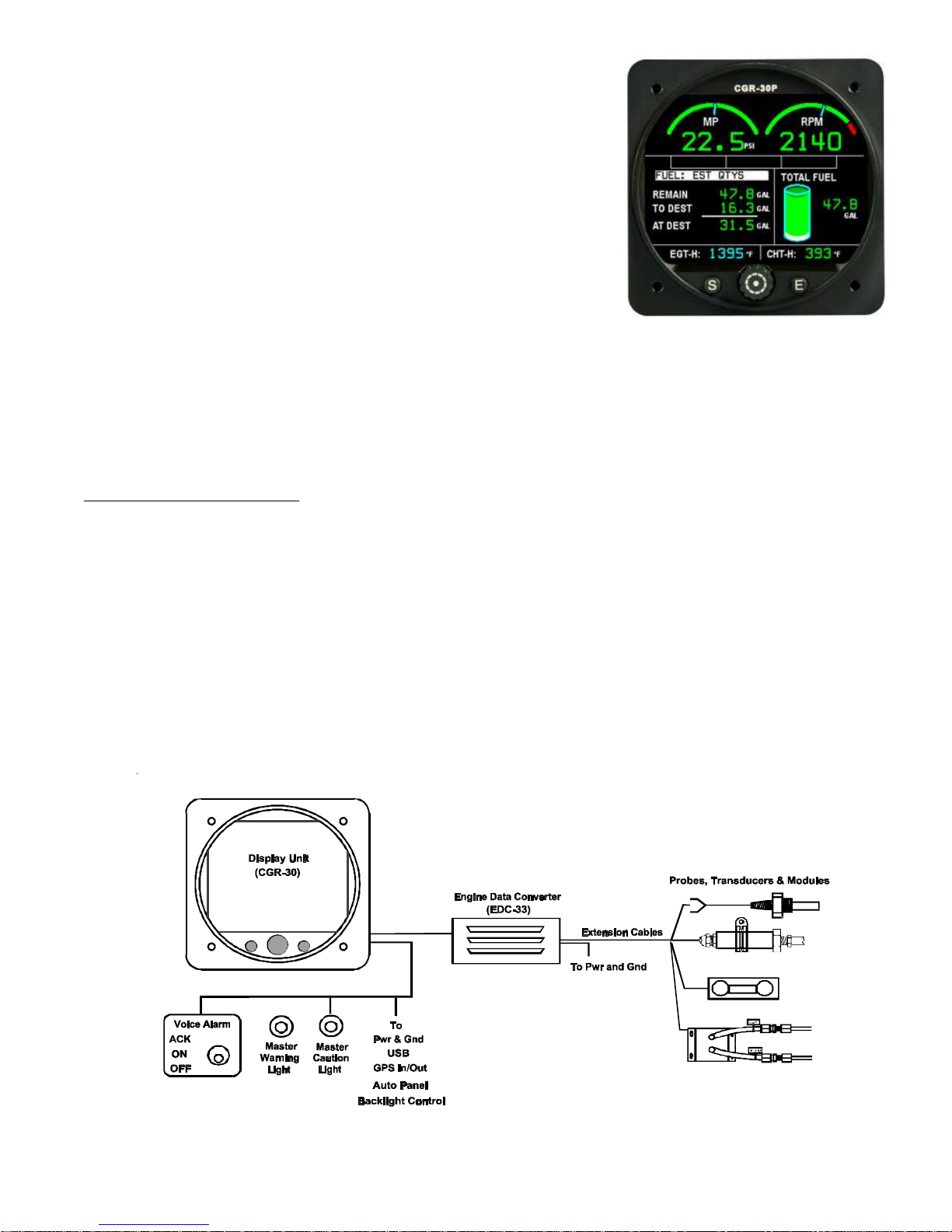
Secondary Screen (see section 3.0): The Secondary screen is
intended to display functions that do not need to be displayed
continuously . Although, one function with a red (warning) and/or yellow
(caution) can be placed on the Secondary screen.
If a primary function on the Secondary screen reaches a red or yellow
operating range, an annunciator located between the two arc gauges
located at the top of the Main Screen will blink. In this way the pilot is
alerted of a potential problem and should view the Secondary screen for
further information.
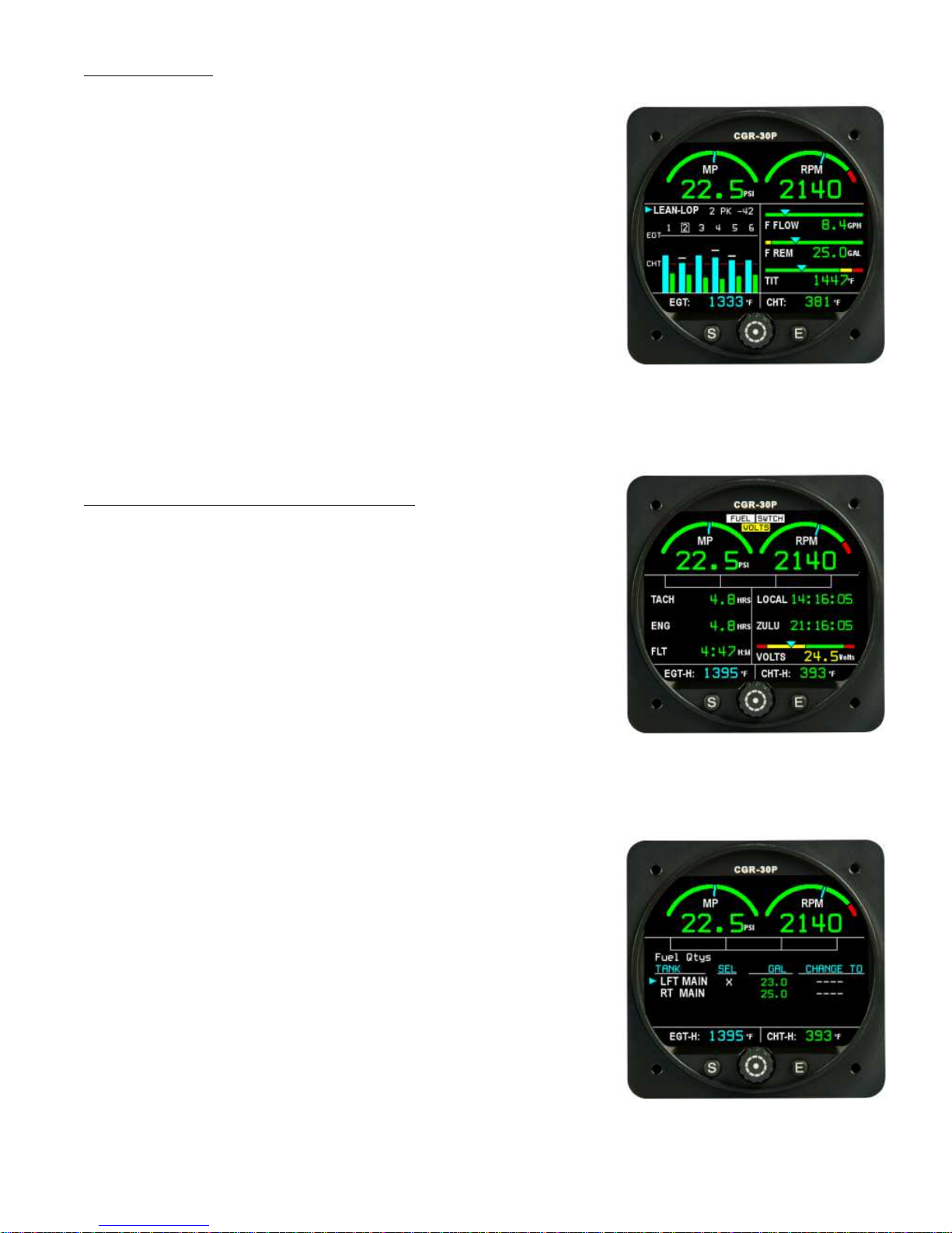
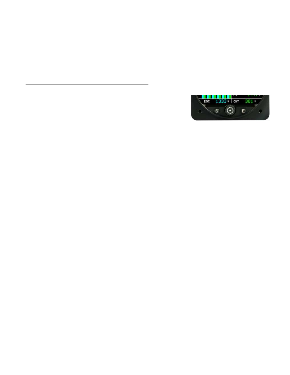
Fuel Qtys Screens (see section 4.0): Depending on the way the
CGR-30P is setup, the Fuel Qtys Screen will display the estimated fuel
levels for the different aircraft fuel tanks or it will display the total fuel
onboard. The setup depends on how the aircraft handles fuel to the
engine (i.e.; if the engine returns fuel to a single fuel tank or if you can
select both tanks, then only total fuel will be displayed). Also, the Fuel
Qtys Screen allows the pilot to add fuel to a tank.
Secondary Screen
Fuel Qtys Screen
5
Page 12
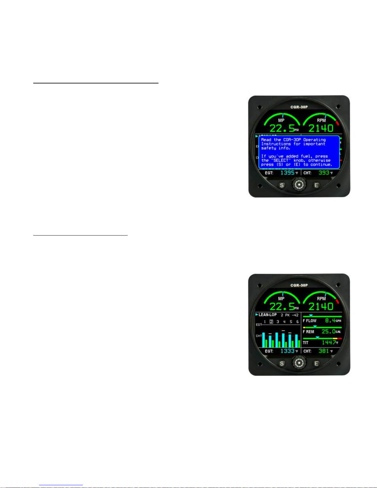
Fuel Data Screen (see section 5.0): The Fuel Data Screen provides
six sets of data based on Fuel Flow and GPS information. This data
includes Range, Distance to Destination, Range after reaching your
Destination, Fuel Remaining, Fuel to Destination, Fuel Reserve, Time to
Empty , Time to Destination, T ime Reserve, Fuel Used for the Flight, Fuel
Used since fuel was Added, Economy (MPGs) and T otal Fuel onboard.
Much of this data depends on an RS232 connection to your GPS.
User Setup Screens (see section 6.0): The User Setup Screen Menu
provides a list of setup screens for setting the K-Factor, setting clocks,
viewing the T ach and Engine Hours, setting the display range for the bar
graph, downloading recorded data and setting up the Recurring Fuel
Alarm.
Fuel Data Screen
System Config Screens (see section 7.0): The System Config
Screens allows Electronics International to setup the CGR-30P for almost any function for any aircraft. These
screens are password protected.
1.3 System Hardware:
The CGR-30P hardware consists of the following three groups of components:
A. Probes, T ransducers and Extension Cables – These components are used to measure pressures,
temperatures, fuel flow , volts, amps, fuel levels and many other engine and aircraft system functions. The
analog signals produced by the transducers and probes are routed through the Extension Cables to
various EDC inputs.
B. EDC (Engine Data Converter) – The EDC-33P converts the analog signals from the probes and
transducers to a digital format. This data is transmitted via a one-wire +5V Serial cable to the CGR
Display .
6
Page 13
C. CGR Display – The CGR receives, processes and displays the Serial EDC data on its TFT color
display . In addition, the CGR receives GPS data, interfaces with the Voice W arning Control Panel and
monitors the external back light control line. Also, the CGR transmits fuel data to the GPS and controls
the external Caution and W arning Lights.
The CGR reduces the number of panel-mounted instruments from around 12 to only 1. The EDC can reduce the
total number of wires routed to the aircraft instrument panel by 50 or more.
1.4 SELECT Knob and Button Operation:
SELECT Knob: The SELECT knob can be rotated or pressed.
Depending on the screen and field being viewed, rotating the knob can
move an arrow , select a digit, or change a digit’s value. Pressing the
SELECT knob will choose the highlighted item.
SCREENS Button: Pressing the SCREENS button sequences the
CGR through the four display screens (Main, Secondary , Fuel Qty and Fuel Data).
EXIT Button: Pressing the EXIT button will exit you out of a specific operation. Repeated presses will exit you
out of the current screen and return you to the Main Screen.
1.5 Display Dimming:
The CGR provides an external dimming control line to dim the display . The CGR can be set to dim on any input
voltage swing. Dimming calibration is setup in the Display & Voice Controls screen found in section 7 of this
manual.
1.6 Cleaning the Screen:
The CGR incorporates a flat panel full color TFT display , which should be protected from scratches. The TFT
display should be cleaned using only isopropyl alcohol and a soft cleaning cloth. Individually wrapped lens-cleaning
tissue (used to clean glasses or plastic lenses) works best.
7
Page 14

Main Engine ScreenMain Engine Screen
Main Engine Screen
Main Engine ScreenMain Engine Screen
2.1 Power-up Add Fuel Message:
2.2 Main Screen Layout:
2.3 RPM and Manifold Pressure:
2.4 Horizontal Strip Gauges:
2.5 Bar Graph Analyzer:
2.5.1 “EGT/CHT” Operating Mode:
2.5.2 “Normalized” Operating Mode:
2.02.0
2.0
2.02.0
2.5.3 “Lean - ROP” Operating Mode:
2.5.4 “Lean - LOP” Operating Mode:
2.5.5 “EGT” Digital Operating Mode:
2.5.6 “CHT” Digital Operation Mode:
2.6 Main Screen Annunciators:
2.7 External Master Caution and Warning Lights:
2.8 Voice Alarm Control Panel (OEM Only):
9
Page 15
The Main Engine Screen displays the aircraft system and engine instruments you will view most frequently during a
flight. There is important information published in the Important Notice section (found in the front of this
manual) that must be read before operating this instrument. Please read the Important Notice section at this
time.
2.1 Power-up Add Fuel Message:
The CGR requires approximately 15 seconds to power-up. Y ou may
want to switch on the Master Switch when first entering the aircraft to
insure the CGR is powered up when you are ready to start the engine.
An “Important Safety Info” and “Add Fuel Message” will appear when
the CGR is fully powered up. The purpose of this message is to remind
you to read the important information and to update the fuel computer if
you have added fuel to the aircraft. The CGR can display the estimated
fuel on-board the aircraft calculated from the fuel flow. This allows you
to cross check the fuel readings on your fuel level gauge to ensure
accuracy. The “Add Fuel Message” can be acknowledged by pressing
the “Exit” button or (if you have added fuel to the aircraft) you can
change the displayed fuel quantity by pressing the “Select” knob.
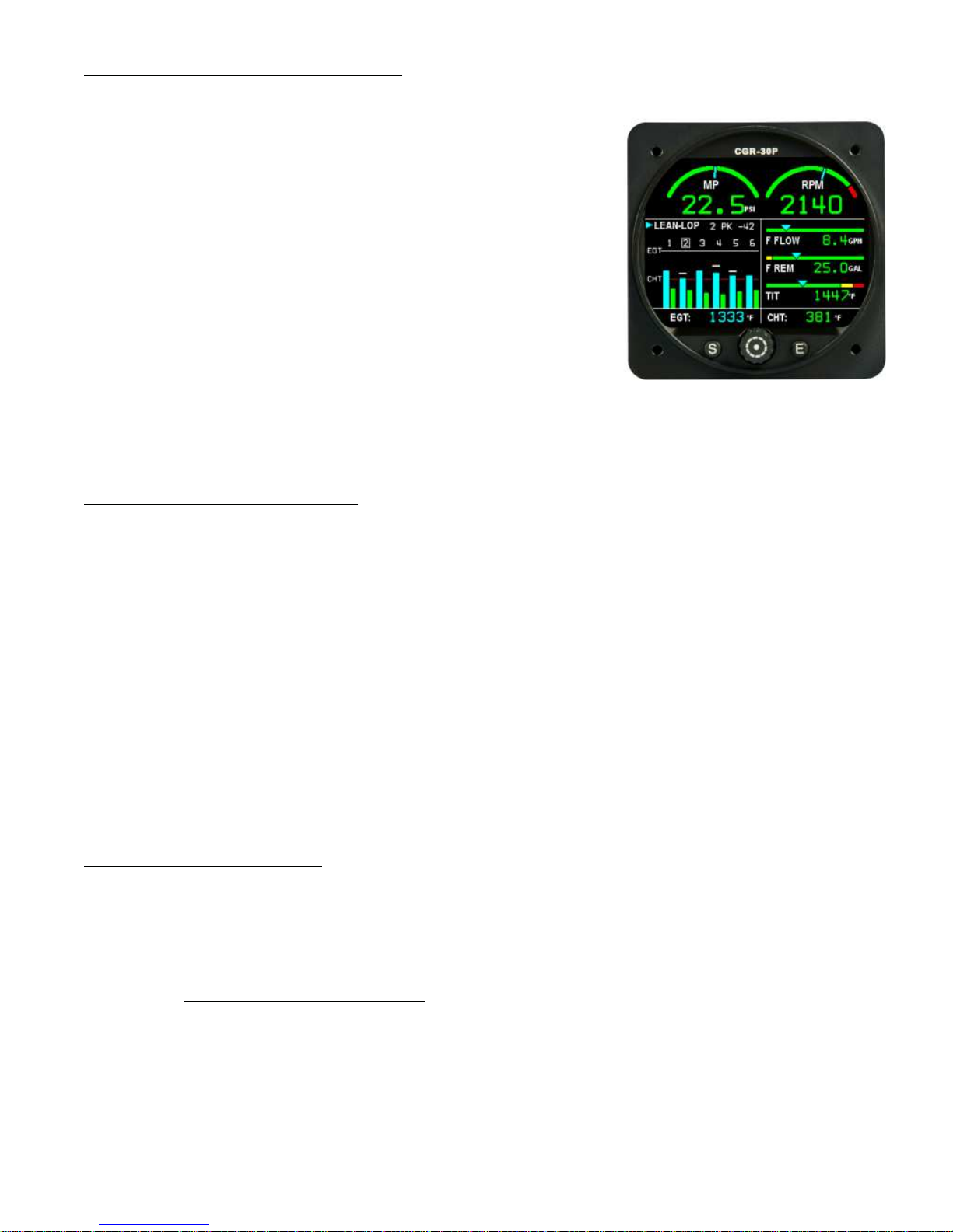
2.2 Main Screen Layout:
The Main Screen is laid out in the following four areas:
RPM and Manifold Pressure (see section 2.3): The RPM and
Manifold Pressure instruments are located at the top of the Main
screen. Each of these instruments incorporates a large arc and
digital display . Other functions may be placed in this location.
Three Horizontal S trip Gauges (see section 2.4): A series of
three Horizontal Strip Gauges (with digital readouts) are located on
the right side of the screen. A number of different functions may be
placed in this location.
Bar Graph (see section 2.5): The Bar Graph is located in the
lower left portion of the Main screen. The Bar Graph monitors
both EGT s and CHT s. The Bar Graph provides both bar graph
and digital formats and incorporates features for leaning, detecting
and diagnosing engine problems. The “SELECT knob controls the display and operation of the Bar Graph
portion of the screen.
EGT/CHT Digital Gauges (see section 2.5): The two digital displays located at the bottom of the Main
screen provides EGT and CHT data based on the bar graph operating mode selected.
11
Page 16
2.3 RPM and Manifold Pressure:
The RPM and M.P. instruments incorporate a digital readout and an
analog arc. The color of the digital readout will reflect the current range
in which the function is operating (i.e., if the RPM is operating in the red,
the digital readout will be displayed in red).
The digital display will blink when the RPM or M.P. operating level
reaches a yellow or red operating range. To stop the blinking, push the
Exit button. Also (if so equipped), acknowledging a voice warning using
the external “Voice Alarm Control Panel” will stop the blinking of any
digital display.
The CGR’s RPM Instrument provides a Mag Out feature in addition to
the arc and digital display. The CGR continually monitors both mag
signals. If one mag fails or is turned off, an appropriate “Mag Out”
warning will be displayed on the appropriate side of the RPM digital display.
2.4 Horizontal Strip Gauges:
L. Mag
Out
The three Horizontal Strip gauges provide the following features:
A. The colored operating ranges shown on the Horizontal Strip can be set up for any aircraft.
B. Each Horizontal Strip Gauge features a pointer (triangle) marking the current operating level. Also, the
pointer allows the pilot to interpret rate and trend information and provides field of vision.
C. A digital display is provided with each Horizontal Strip Gauge.
D. The digits on the digital display will blink when a function’ s operating level reaches a yellow or red
operating range. T o stop the blinking, push the Exit button. Also (if so equipped), acknowledging a voice
warning using the external “V oice Alarm Control Panel” will stop the blinking of any digital display .
2.5 Bar Graph Analyzer:
The Bar Graph Analyzer has six operating modes: EGT/CHT, Normalized, Lean ROP , Lean LOP , EGT and
CHT. The CGR’ s current mode of operation is displayed in the top left portion of the Bar Graph Display. The
SELECT knob may be used to change operating modes.
2.5.1 “EGT/CHT” Operating Mode: The vertical bars are arranged to show the EGT and CHT for
each cylinder. The operating ranges for the EGT bars may be set to match your engine’ s operating
temperatures (i.e.; if your full rich low power EGT readings are around 1100’F , set your Low EGT Range
for 1000’F . If your peak EGT readings are around 1500’F , set your High EGT Range for 1525’F). The
high and low EGT ranges may be set in the “EGT/CHT Bar Graph Setup” screen (see section 6).
12
Page 17

If the EGT for a cylinder exceeds the pilot set High EGT Range,
the bar for that cylinder will turn white and blink. This feature
provides the pilot with a warning of a high EGT . The F AA does
not allow exceedance of user set EGT s to display in red or
yellow .
If the CHT for a cylinder exceeds the set limit, the bar for that
cylinder will turn red and blink.
The current Digital Display Mode of operation is designated in
the top right portion of the Engine Analyzer display . The
selections are Select, Diff, Scan and Hottest. The Digital Display
Mode controls what will be displayed in the digital section at the
bottom of the Bar Graph display .
Select Mode: The Select Mode allows the pilot to select a cylinder (displayed with a box around the
cylinder number). The EGT and CHT for the cylinder selected are shown in the bottom portion of the
display .
Diff Mode: The Diff Mode displays the difference between the hottest and coldest EGT and CHT .
The values are displayed at the bottom of the Bar Graph and are designated by EGT -D and CHT -D
If a differential limit is exceeded, the digital values will be displayed in white. The differential limits are
set in the “EGT/CHT Bar Graph Setup” screen (see section 6). The differential limits allow the CGR
to detect developing engine problems before they become expensive repair bills.
Scan Mode: The Scan Mode automatically scans through all of the cylinders. As it scans through the
cylinders, the EGT and CHT numeric values are displayed in the bottom portion of the Bar Graph
display . The scan rate can be set in the “EGT/CHT Bar Graph Setup” screen.
Hottest Mode: The Hottest Mode displays the hottest EGT and CHT in the digital display below
the bars. This is the favorite mode of operation for most pilots.
2.5.2 “Normalized” Operating Mode: The Normalized Mode of operation is an engine diagnostic tool
that allows comparison of the current EGT s and CHT s to a reference (past flight). By normalizing the EGTs
and CHT s the vertical bars are brought to the same level, creating a reference baseline.
The EGT and CHT bars may be normalized (leveled) at any time by pushing and holding the Select Knob
for four seconds and following the instruction in the pop-up window .
The offset data to level the bars is stored in CGR permanent memory . The Normalized Mode allows
changes that have occurred in the engine to be spotted easily . This makes it possible to detect trends over
several flights, days, weeks, and even years.
13
Page 18

2.5.3 “Lean-ROP” Operating Mode: This operating mode was designed to assist the pilot in leaning
the engine Rich-of-Peak EGT . As you lean, the EGT bars for all cylinders will rise. When the first cylinder
reaches peak EGT a tattletale marker will appear at the top of that cylinder’s bar . Enrichen the mixture and
the first cylinder to reach peak and the T emp Below Peak (on the rich side) will be displayed at the top right
of the bar graph display area.
2.5.4 “Lean-LOP” Operating Mode:
Important Notice: The engine must be leaned and operated in
accordance with the POH and engine manufactures
recommendations. Information in this manual is for reference
only and does not make any recommendations.
This operating mode was designed to assist the pilot in leaning
the engine Lean-of-Peak EGT . As you lean, the EGT bars for all
cylinders will rise. When the first cylinder reaches peak EGT a
tattletale marker will appear at the top of that cylinder’s bar . As
you continue to lean, additional tattletale markers will be placed
at the top of the appropriate bar as each cylinder reaches peak
EGT . This gives a quick visual reference as to which cylinders
have reached peak EGT and at what temperature each cylinder
peaked. If a false peak is detected (an EGT dips and then starts
increasing again), the CGR will reset the tattletale marker for that cylinder and once again look for the true
peak.
The data provided in the top portion of the display will show the first cylinder to reach peak EGT and the
current temperature below peak for that cylinder.
2.5.5 “EGT” Digital Operating Mode: The EGT Digital Operating Mode provides a pictorial
representation of the engine and the EGT s for each cylinder in a digital format. The Digital Display Modes
available are: “Actual” and “Diff.”
Actual: In the Actual Mode the current EGTs for each cylinder are displayed. The data at the
bottom of the display provides the difference (or spread) between the hottest and coldest EGT and
CHT.
Diff: In this Mode, the coldest cylinder is indicated by a reading of “0.” Each of the other cylinders
will display the difference between its temperature and the temperature of the coldest cylinder. The
data at the bottom of the display provides the temperature of the hottest EGT and CHT. Differential
readings provide valuable diagnostic information.
2.5.6 “CHT” Digital Operating Mode: The CHT Digital Operating Mode provides a pictorial
representation of the engine and the CHT s for each cylinder in a digital format. The Digital Display Modes
available are: “Actual” and “Diff.”
14
Page 19

2.6 Main Screen Annunciators:
Located between the RPM and M.P. instruments on the Main Screen
are the following annunciators:
Fuel - When the estimated total fuel drops below approximately
45 minutes the “FUEL” annunciator will blink. The trigger level is based on 75% engine power and a fuel
specific of .08 gal/hr/Hp. The Low Fuel Trigger is set by Electronics International based on the aircraft data
provided.
Switch – When the “Recurring Fuel Alarm Qty” has been burned the “SWITCH” annunciator will blink.
This provides a reminder for the pilot to switch fuel tanks. The “Recurring Fuel Alarm Qty” can be set or
disabled in the “Fuel Alarm and Unit Info”screen, found in the User Setup Screens Menu (see section 6).
Secondary Screen Annunciator – If a function with a red and/or yellow limit is placed on the Secondary
Screen and the function is operating in a yellow or red range, the name of the function (in this case VOLTS)
will blink in the color of its operation. All functions monitored by the CGR-30P with yellow and/or red
range markings are either viewed or annunciated on the Main screen.
2.7 External Master Caution and Warning Lights:
A red external W arning Light and a yellow Caution Light (provided with the CGR) may be mounted in front of the
pilot, high on the aircraft instrument panel. These lights provide a heads-up visual warning. The red W arning Light
will blink any time the operating level of any monitored function reaches a red operating limit and the
yellow Caution Light will blink any time the operating level of any monitored function reaches a
yellow operating limit.
Pushing the Exit Button while viewing the Main screen will acknowledge the blinking and the blinking
will stop. Also, acknowledging a voice warning using the external “Voice Alarm Control Panel” will
stop the blinking of the Caution and W arning Lights.
Acknowledging a yellow blinking display will cause the yellow Caution Light to go out. Acknowledging a red
blinking display will cause the red W arning Light to stop blinking and go solid red. If at any time another function
reaches a red and/or yellow operating limit, the approprate Caution or W arning Light will once again blink.
R
CGR-30
Y
2.8 Voice Alarm Control Panel (OEM Only):
The Voice Alarm Control Panel is an external panel used to control the voice warnings provided by the CGR. The
CGR voice warning system is a powerful system that provides an immediate and intelligent audible warning
regardless of the pilot’s head position or focus. The instant an operating level of any function reaches a red and/or
yellow operating limit, a chime will sound in the headset and a pleasant female voice will annunciate a phrase, such
as: “Check Oil Pressure,” or “Check Fuel Pressure.”
15
Page 20

Secondary ScreenSecondary Screen
Secondary Screen
Secondary ScreenSecondary Screen
3.1 RPM and Manifold Pressure Gauges:
3.2 Three Annunciators:
3.3 Six Horizontal Strip and/or Digital Gauges:
3.4 EGT/CHT Digital Gauges:
3.03.0
3.0
3.03.0
17
Page 21

The Secondary screen is divided into the following four areas; RPM and
M.P gauges, three Annunciators, six Horizontal Strip gauges and the
EGT/CHT digital gauges.
3.1 RPM and Manifold Pressure Gauges:
The RPM and Manifold Pressure gauges are located at the top of the
Secondary screen. Each of these instruments are carried over from the
Main screen.
3.2 Three Annunciators:
The three annunciators located just below the RPM and M.P. gauges
provide a status indicator for the three horizontal strip gauges found on the Main screen. If any one (or all) of the
strip gauges on the Main screen transition into a yellow or red operating area, the appropriate annunciator on the
Secondary screen will blink the name of the function in yellow or red. To acknowledge and stop the blinking, press
the Exit button while viewing the Main screen. All functions monitored by the CGR-30P with yellow and/or red
range markings are either viewed or annunciated on the Secondary screen.
3.3 Six Horizontal Strip and/or Digital Gauges:
Six additional gauges (horizontal Strip and/or Digital) are provided on the Secondary screen. Only one of these
gauges should have yellow and/or red range markings. The function with the yellow and/or red range markings will
be annunciated on the Main screen. The CGR-30P has a number of derived functions (HP, Flight Time, Tach
Time, Local Time, Zulu Time, etc.) that can be placed on the Secondary screen.
3.4 EGT/CHT Digital Gauges:
The digital display located at the bottom of the Secondary screen provides the hottest EGT (EGT-H) and hottest
CHT (CHT-H). This displayed data is carried over from the Main screen.
18
Page 22

4.1 Fuel Quantity:
4.2 Selecting a Tank:
4.3 Adding Fuel:
4.4 K-Factor Adjustments:
FUEL QTYS ScreenFUEL QTYS Screen
FUEL QTYS Screen
FUEL QTYS ScreenFUEL QTYS Screen
4.04.0
4.0
4.04.0
20
Page 23

4.1 Fuel Quantity:
The Fuel Qtys screen provides the current estimated fuel level for each
fuel tank or the estimated total fuel on-board the aircraft. Estimated
individual fuel tank levels may or may not be displayed depending on the
configuration of the fuel system for the aircraft (i.e.; the CGR-30P will
only show Total Fuel on-board for an aircraft that feeds the engine from
one tank and returns the fuel to another tank or where both tanks can be
selected).
WARNING: The estimated fuel levels are only estimates and should
not be the only means of determining the fuel level in a fuel tank.
4.2 Selecting a Tank:
If the estimated fuel level for each tank is displayed, you are required to select the appropriate tank in the CGR-30P
at the same time you physically select the tank in the aircraft. In this way the CGR-30P provides an estimate of the
fuel in each tank of the aircraft. This is accomplished with the Select Knob. If only the total fuel on-board is
displayed, synchronizing the selection of tanks in the CGR-30P with the physical selection of tanks in the aircraft is
not required.
4.3 Adding Fuel:
To provide an estimate of the fuel on-board the aircraft the fuel levels shown in the CGR-30P must be updated
when fuel is added to the aircraft. A blue add fuel screen is displayed at every power-up to remind the pilot to
update the fuel levels displayed in the CGR-30P.
To add fuel, navigate to the “Change To” column in the Fuel Qty screen using the Select Knob. There are two
default fuel levels (set in the Fuel Tank Setup screen) and an add amount feature available.
22
Page 24

4.4 K-Factor Adjustments:
Fuel levels are only estimates of the fuel on-board the aircraft and are
derived from fuel flow. Accurate fuel flows depend on an accurate KFactor. If after filling the fuel tanks you find an error in the Fuel Qty
“SINCE ADD” (as shown on the “Fuel: Est Used” screen) when compared to the actual fuel used (as read off the fuel pump), you can manually or automatically adjust the K Factor. The K-Factor is a measurement of the pulses per gallon that the flow transducer outputs. Due to
variations in the installation of the flow transducer, it may be necessary to
adjust the K-Factor for the first few flights in order to get an accurate fuel
remaining, fuel used and flow reading.
The K-Factor should be changed only when the fuel tanks have been
filled accurately on level ground. After a few adjustments of the KFactor, the fuel remaining and the fuel used as calculated by the CGR30P should be within a few gallons (or less) of actual and should not need further adjustment. Navigate to the “Fuel
K-Factor” screen to change the K-Factor (see section 6.1).
23
Page 25

5.1 Total Fuel Cylinder:
5.2 Fuel: FLOW
5.3 Fuel: EST DIST
5.4 Fuel: EST QTYS
5.5 Fuel: EST TIME
5.6 Fuel: EST AT DEST
5.7 Fuel: EST USED
FUEL Data ScreenFUEL Data Screen
FUEL Data Screen
FUEL Data ScreenFUEL Data Screen
5.05.0
5.0
5.05.0
24
Page 26

The Fuel Data screens provide flight data based on fuel flow, fuel remaining, fuel used and GPS data. The screens provide the follow data:
5.1 Total Fuel Cylinder:
For all the fuel data screens the estimated Total Fuel is provided in the
right hand portion of the display. The bottom white portion of the
displayed cylinder represents the last 45 minutes of fuel on-board. The
fuel above this amount will be displayed in green.
When the estimated Total Fuel drops below approximately 45 minutes
(white area), the “FUEL” annunciator on the Main screen will blink. The
45 minute trigger level is based on 75% engine power and a fuel specific
of .08 gal/hr/Hp. This tigger is set by Electronics International based on
aircraft data provided in the worksheet.
5.2 Fuel: FLOW
This screen provides the current Fuel Flow for the engine and if the Recurring Fuel Alarm is set, the quantity or time
before the next alarm (see section 6.5)
5.3 Fuel: EST DIST
This screen provides the following Distance data:
RANGE – This is the distance the aircraft can travel based on the current fuel flow, fuel remaining and GPS
ground speed.
To DEST – This is the distance to the destination based on GPS data.
At DEST – This is the calculated distance in reserve after the aircraft reaches its destination
(Range – Distance to Destination).
5.4 Fuel: EST QTYS
This screen provides the following calculated Fuel Quantity data:
REMAIN – This is the total estimated fuel remaining on-board
the aircraft.
To DEST – This is the estimated fuel required to reach the GPS
Destination.
At DEST – This is the calculated fuel in reserve after you reach
your destination (Fuel Remain – Fuel required to reach your
Destination).
26
Page 27

5.5 Fuel: EST TIME
This screen provides the following calculated Time data:
To EMPTY – This is the estimated time to empty based on the
fuel remaining and the current fuel flow.
To DEST – This is the time required to reach your destination
based on GPS data received.
At DEST – This is the reserve time after you reach your destination (Time to Empty – Time to Destination).
5.6 Fuel: EST AT DEST
This is a display of all the estimated reserves (after you reach your destination). The CGR-30P calculates the
Distance, Time and Fuel Qty in reserve early in the flight allowing the pilot to manage fuel and make critical decisions as the flight progresses.
5.7 Fuel: EST USED
This screen provides the following calculated Fuel Used data:
Flight – This is the fuel used for the current flight. When the
flight timer starts, this field is reset to zero and fuel accumulates as
the flight progresses.
Since ADD – This is the fuel used since your last fill-up or if you
did not fill-up, since you added fuel.
Economy – This is your current economy in nautical miles per
gallon. It is calculated from the current fuel flow and GPS
ground speed. This can be very helpful in dealing with winds
aloft and leaning.
Leaning past 100 degrees rich of peak EGT reduces horsepower and therefore airspeed. It also reduces
fuel flow. The displayed Economy allows you to determine if continuing to lean produces a true fuel savings
and how much. Also, different altitudes can have different winds aloft. In this case the displayed Economy
allows you to determine if one altitude provides a fuel saving over another.
27
Page 28

User Setup ScreensUser Setup Screens
User Setup Screens
User Setup ScreensUser Setup Screens
6.1 Fuel K-Factor Screen:
6.2 Clock and Hour Meters Screen:
6.3 EGT/CHT Bar Graph Setup Screen:
6.4 USB and Data Recording Screen:
6.5 Fuel Alarm and Unit Info Screen:
6.6 System Config Screens Menu:
6.06.0
6.0
6.06.0
28
Page 29

The User Setup screens are provided to allow the pilot to adjust the KFactor, setup the Local and Zulu clocks, setup the EGT/CHT Bar
Graph, setup Data Recording, and activate the Recurring Fuel Alarm.
To display the User Setup Screens Menu, push and hold the
Select Knob for approximately 3 seconds while viewing the Main
screen. The following is a list of the User screens available:
6.1 Fuel K-Factor Screen:
Note: This screen is not accessible during engine operation.
If after filling the fuel tanks you find an error between the fuel displayed in
the “Calc-Fill” column (as shown on the screen) and the actual fuel used (as read off the fuel pump), you can
manually or automatically adjust the K-Factor. The K-Factor is a measurement of the pulses per gallon that the
flow transducer outputs. Due to variations in the installation of the flow transducer, it may be necessary to adjust the
K-Factor for the first few flights in order to get an accurate fuel remaining, fuel used and fuel flow reading.
The K-Factor should be changed only when the fuel tanks have been
filled accurately on level ground. After a few fill-ups and adjustments of
the K-Factor, the fuel remaining and the fuel used as calculated by the
CGR-30P should be within a few gallons (or less) of actual and should
not need further adjustment. Use the following fields, as necessary, to
correct the K-Factor.
Note: The Fuel K-Factor Screen is not accessible while in flight.
CALC-FILL – This column is calculated by the CGR-30P and
is the fuel used since the last fill-up and the calculated fuel necessary to fill the tank.
ACT-FILL – Enter the fuel from the fuel pump required to fill the fuel tank(s) into this field. The difference
between the CALC-FILL and the ACT-FILL is the error. Adjusting the K-Factor will correct this error.
Feed K-Factor – This field provides the current K-Factor and the percentage error between the calculated
fuel to fill the tank(s) (CALC-FILL) and the measure fuel to fill the tank(s) (ACT-FILL).
Return K-Factor - This field is used to adjust the K-Factor for a flow transducer in the fuel return line.
Normally this field will not be used.
30
Page 30

Auto Adjust K-Factor – This field activates the automatic calculation of the new K-Factor to remove the
error in the Fuel Remaining and Fuel Used. The K-Factor can be adjusted manually by using the following
formula:
(Calc’d Used Since Fill up) x (current K-Factor)
New K-Factor = —————————————————————
Actual Fuel Used (Pump Reading at Fill up)
WARNING: When you change the K-Factor, the accuracy of the CGR-30P’s estimated Fuel Remaining,
Fuel Used and Fuel Flow readings will change.
6.2 Clock and Hour Meters Screen:
This screen allows you to set today’s date, Local and Zulu time and view
the current Tach Time and Engine Hours. The date and time is used to
stamp each record in the flight logs. The Tach Time is the total time the
engine has been operated over 1300 RPM. The Eng Time is the total
time the engine has been operated. Eng Time is is used for TC work or
logging flight hours.
6.3 EGT/CHT Bar Graph Setup Screen:
The Bar Graph may be setup using the following fields:
EGT Range Low & High – The Low and High EGT Range settings determine the operating range of the
bar graph display . The goal is to set the range so the bars are
low in the display during full rich low power operation and high in
the display during lean cruise operation. It will then be possible
(at a glance) to see how rich or lean your engine is running.
Set the “High EGT Range” field for 30°F above peak EGT for
the hottest cylinder.
Set the “Low EGT Range” field for 50°F below the coldest EGT
when operating full rich low power.
When an EGT reaches a High Range limit, the bar for that
cylinder will blink in white alerting the pilot of a possible over
temp condition.
Hottest to Coldest Difference (EGT and CHT) – This field allow you to set the maximum spread
between the hottest and coldest EGT and CHT. This provides a tool to help detect engine problems early.
False warnings are annoying and can create complacency towards alarms in general. EGT and CHT
spreads will vary with engine power, mixture settings and different altitudes. To protect against false alarms
31
Page 31

while maintaining good EGT and CHT Differential Limits, fly with the CGR-30P and note the maximum
spread for both EGTs and CHTs for all stages of flight. Set the EGT and CHT “Hottest to Coldest Difference” field to 35’F above the maximum spread.
EGT/CHT Scan Rate – This field sets the rate at which the digital EGT and CHT readout (at the bottom
of the bar graph display) will scan from one cylinder to the next, when in the Scan Mode.
6.4 USB and Data Recording Screen:
Note: This screen is not accessible during engine operation.
This screen allows you to download flight data to the USB Data Stick
and set the Data Sample Rate. The Data Sample Rate is the time interval
between recorded data. The CGR-30P can record up to 1500 flights
before it records over the oldest flight first. The USB port may be found
mounted in the instrument panel or hanging under it.
Flight data is recorded and downloaded in a comma delimited format.
This allows the file to be ported directly into Excel. The file names are
formatted as follows (see Appendix A2.0 for more information):
Flt0001_20130123P.csv
Flt0001 - This is Flight Number 1.
_2013 - This is the Year.
01 - This is the Month (January)
23 - This is the Day (23rd)
P - P = Instrument was only powered-up, E = The instrument was powered-up and the
engine was running, F = The aircraft was flown (the flight timer started).
The current Flight Number is shown at the bottom of the screen. This number increments each time the CGR-30P
is powered-up.
6.5 Fuel Alarm and Unit Info Screen:
This screen provides the following features:
Recurring Fuel Alarm – A recurring fuel alarm may be set to
alert the pilot each time a set amount of fuel is consumed. For
example; if the aircraft has 40 gallons of fuel on-board and the
alarm was set for 10 gallons, when the fuel remaining dropped to
30 gallons you would get an alarm. Also, the alarm will recur at
20, 10 and 0 gallons. The word “SWITCH” between the RPM
and M.P. gauges will blink in white when the Recurring Fuel
Alarm is activated. The alarm is intended to help the pilot
manage fuel by reminding him/her to switch fuel tanks. The alarm
32
Page 32

can be used for other purposes. To turn off the alarm, press the Exit button while viewing the Main screen.
The time or fuel quantity to the next alarm is displayed on one of the Fuel Data screens (see section 5.2).
Aircraft and CGR-30P Data – The lower section of this screen provides aircraft and CGR data. The
Aircraft ID is the aircraft for which the CGR-30P was configured.
6.6 System Config Screens Menu:
The “System Config Screens Menu” provides a list of screens that are
used to configure the CGR-30P for a specific aircraft. These screens are
password protected. To display the “System Config Screens
Menu,” push and hold the Select Knob for approximately 3 seconds while viewing the Main screen. Next, select the “System
Config Screens Menu” at the bottom of the screen. Section 7
provides a list of the available screens.
If you have access but do not have the knowledge to properly change an
item, seek help. All changes must be verified that they provide proper
CGR-30P operation for your aircraft/engine.
WARNING: The System Configuration Screens allow you to
change important setup and calibration data that may affect the
way the aircraft is operated. If any data is changed in any one of the System Configuration Screens, it is
important to verify that the change is proper for your aircraft. If any changes have been made, backup
the CGR-30P configuration files to a USB Data Stick.
You must set a unique password to protect all of the calibration and setup data in the CGR-30P. If setup
or calibration data is inadvertently or improperly changed, the CGR-30P could display inaccurate readings that may lead to improper operation of the aircraft or engine. This could result in engine damage
and/or an emergency situation. Verify that the CGR-30P is working properly for the aircraft and engine
for which it is intended BEFORE the aircraft is released for normal operation.
33
Page 33

System Configuration ScreensSystem Configuration Screens
System Configuration Screens
System Configuration ScreensSystem Configuration Screens
7.1 USB Config and SW Prg Manager Screen:
7.2 Change Passwords Screen:
7.3 Aircraft ID Screen:
7.4 Hour Meters and Flight Timers Screen:
7.5 Serial Port and EDC Setup Screen:
7.6 Engine and EGT/CHT Bar Graph Setup Screen:
7.7 Fuel Tank Setup Screen:
7.07.0
7.0
7.07.0
7.8 Display and Voice Controls Screen:
7.9 CGR Input/Output Tests Screen:
7.10 Horsepower Calibration Screen:
7.11 Function Configuration Screen:
34
Page 34

7.1 USB Config and SW Prg Manager Screen:
This screen provides a method to update the software and backup and
retrieve configuration data. The data fields operate as follows:
Update The SW Program (3 Steps) - This section allows you
to update the main CGR-30P software program. Your CGR’s
current software version is listed on this screen under “Curr
Revision.” The new software program must be placed in the
“sw” directory on the USB Data Stick and must be the only file
in that directory.
Config Files (Limits, Redlines, etc.) - This section allows you
to backup configuration files to the USB Data Stick, or retrieve
configuration files from the USB Data Stick. The configuration
files contain all of the data necessary to set up the CGR-30P for
your aircraft and engine (engine type, GPS interface, all instrument and bar graph limits, fuel tank cal data, EDC mapping, screen layout, all calibration data for all probes
and transducers, etc.).
The “Retrieve ALL Backup Config Files” command reads all the stored configuration data on the USB Data
Stick. If the configuration data was NOT stored to the USB Data Stick by the same CGR-30P that is
retrieving it, the command will fail. Each CGR-30P system has the following unique calibration data:
A. Temp Comp Diode offset (this diode is located on the middle connector of the EDC).
B. PT-30ABS, Manifold Pressure offset.
C. PT-30Alt, Pressure or Cabin Altitude calibration data.
D. Horsepower calibration data.
E. Fuel Tank calibration data.
F. G-Meter
Certified Unit Field – If this field is set to “Yes” and the EGT’s are set to Primary in the “Engine & Bar
Graph Setup” screen, the EGT Low and High Ranges cannot be set by the user.
Reserved for EI use Field – This field is for E.I. support personel only.
Button Board Trk Num – This field provides Button Board software information for E.I. support
personel.
7.2 Change Passwords Screen:
The CGR-30P provides a number of screens for the pilot to use during flight, none of which require a password. It
also provides many System Configuration Screens that are used to configure the CGR-30P for a specific aircraft.
Some of the aircraft functions (fuel level, engine hours, GPS port setup, etc.) must be calibrated or setup during
installation and some are setup at the factory or by an OEM.
36
Page 35

The CGR-30P provides four levels of passwords for configuring, setting
up and calibrating the unit. During ground operation all of the System
Configuration Screens and data may be viewed without a password, but
a password is required to change data.
User Password – The User Password allows the pilot to
lockout any changes to fields in the User Setup Screens. The
password is set to “blank” when the system is setup at the
factory. This allows easy access for simple changes. To lock
these screens, set a User Password. Be sure to record this
password and keep it in a safe place.
Maintenance Password – The Maintenance Password allows
the installer to calibrate the fuel tanks, set the #1 cylinder (for the
Bar Graph display), set the Tach Time, setup the serial ports, backup configuration files and retrieve configuration files.
OEM and EI Password – The OEM and EI Passwords allow full access to all fields in all screens.
The Unlock codes at the bottom of the screen allow Electronics International to decode any of the current passwords.
7.3 Aircraft ID Screen:
The Aircraft ID Screen identifies the aircraft for which the CGR-30P was configured. Do Not install a CGR-30P
into an aircraft for which it was not configured. Limits and calibration data may not be appropriate for a different
aircraft.
7.4 Hour Meters and Flight Timers Screen:
This screen is used to setup the current Tach Time, Engine Time and the triggers for the Flight Timer. Engine Time
is used for TC work or logging flight hours.
7.5 Serial Port and EDC Setup Screen:
This screen is used to setup the four serial ports. The Com1, RxFunction field should be used for the EDC (19200, 8, None, 1). Use
Com2, Rx-Function field to monitor a second EDC. Use Com3, RxFunction field to receive GPS data and the Tx-Function to send fuel flow
data to the GPS. Check GPS requirements for proper settings. Use
Com4, Rx-Function field to monitor the CO Guardian detector.
37
Page 36

7.6 Engine and EGT/CHT Bar Graph Setup Screen:
The “Engine Parameters” section allows you to set the number of cylinders and the location of the #1 cylinder. This sets the number of bars to
be shown in the Bar Graph on the Main screen. Also, when the engine is
displayed in the EGT or CHT Digital mode, the #1 cylinder will be
shown correctly.
The “Bar Graph Configuration” fields provide the following:
Bar Graph Format – This allows the bar graph to display only
EGTs, only CHTs or both.
Is EGT a primary gauge – If the EGTs are primary, the user
will not be allowed to change EGT limits.
All Cyl EGTs same as #1 – This allows the limits set for cylinder #1 to be used for all the EGT limits.
All Cyl CHTs same as #1 – This allows the limits set for cylinder #1 to be used for all the CHT limits.
EGT Difference Limit – This sets the maximum spread allowed between the EGTs. This parameter also
shows up in a User screen.
CHT Difference Limit – This sets the maximum spread allowed between the CHTs. This parameter also
shows up in a User screen.
EGT/CHT Scan Rate (secs) – This is the rate at which the cylinders are scanned (in the SCAN mode)
and the data is displayed to the pilot. This parameter also shows up in a User screen.
EGT Ext Warning – If this field is set to “On” and an EGT differential or upper limit is exceeded, the
external warning light will blink.
7.7 Fuel Tank Setup Screen:
This screen allows you to setup the fuel tanks for estimating the fuel levels based on fuel flow. Estimated individual
fuel tank levels may be displayed or the Total Fuel on-board may be displayed. There are advantages and disadvantage for displaying estimated fuel in each tank versus displaying only the total fuel on-board.
38
Page 37

Displaying estimated fuel in each tank:
Advantages - The CGR-30P displays the estimate of the fuel
level for each fuel tank.
Disadvantages - If the engine can feed from one fuel tank and
return fuel to another fuel tank, a second fuel flow transducer
must be installed in the fuel return line.
- Each time you switch fuel tanks you must switch tanks in the
CGR-30P. If you forget, the fuel remaining for all the tanks will
be inaccurate.
- When fuel is added to the aircraft’s fuel tank, each tank in the
CGR-30P must be updated.
The columns in the Fuel Tank Setup Screen provide the following data:
Tank Name – This field allows you to name the fuel tanks. If only the total fuel on-board is to be displayed, use the name “TOTAL.”
TP – Enter the fuel tank type: F = Feeds the engine, X = Transfers fuel to another tank.
Full Amt – Enter the full fuel level. This will be used as a pre-select amount.
Tab Amt – If for some flights you only partially fill the tank, enter partial fuel level. This will also be used as
a pre-select amount.
Warn Amt – Enter the low fuel level used to activate the low fuel warning.
Return/Xfer-To – If this tank feeds the engine and does not have a fuel return (or returns fuel to itself),
place the Tank Name in this field. If this tank only transfers fuel to another tank (does not feed the engine),
place the Tank Name to which the fuel will be transferred in this field. As you add tanks to this screen they
will show up in the “Return/Xfer-To” field.
At the bottom of the screen are the following fields:
Flow Rate Units – Fuel flow is received in US Gal/Hr. This field allows you to modify the displayed fuel
flow value to other units. The value will change but the units will not. The display units can be changed in
the “Function Configuration” screen.
Fuel Weight in US Pounds – This field sets the weight of the fuel which is used for calculating fuel flow in
various units.
Min Fuel Used For K-Factor – The K-Factor (used to calibrate the Fuel Flow) should not be calculated
for short flights. This field sets the minimum fuel that must be used before the “Auto Adj K-Factor” feature
can be used.
39
Page 38

7.8 Display and Voice Controls Screen:
The two voice control sections in this screen are for future development
and have not been activated at this time.
The Backlight Setup section of this screen allows you to set the Dim and
Bright levels of the CGR-30P display to any control input voltage. The
intent is to match the CGR-30P’s intensity to your aircraft’s current
backlight intensity of other instruments in the panel. To setup the CGR30P backlight follow the steps listed below. If a dedicated dimming
control pot is required for the CGR-30P, order Electronics
International’s CP-1.
1. The Control Voltage (Vin) from the aircraft’s dimming control
pot is displayed at the bottom of the screen. Adjust the dimming
control pot on the aircraft from dim to bright and check that the
Vin field changes a minimum of 2-volt. The Vin value can increase or decrease as the knob is turned from
full dim to full bright.
2. With the aircraft engine off, set the aircraft’s dimming control knob to full dim and then rotate it 1/8 turn
towards bright. Set the “DIM” field to “SET” and push the CGR’s Select Knob.
3. Set the aircraft’s dimming control knob to full bright and then rotate it 1/8 turn towards dim. Set the
“BRIGHT” field to “SET” and push the CGR’s Select Knob. Exit all fields and check that the CGR-30P
dimming operates properly.
To set the CGR-30P dimming operation to your preference you may have to perform this procedure with different
dimming control settings. Note: When the engine is running, the alternator will increase the bus voltage which may
slightly change the backlight intensity. The above procedure should compensate for this.
7.9 CGR Input/Output Tests Screen:
The fields in this screen operate as follows:
Four GPS Data Fields - If the CGR-30P is connected to your GPS, the top portion of this screen provides the current GPS data received by the CGR-30P.
Caution and Warning Lights Fields - The Caution and Warning Light fields turn on and off the external
caution and warning lights.
USB 5v Control Field – This field turns on and off the 5-volts to the USB. Warning – The USB port
must not be used as a charger or to provide power to any other device except a USB Data Stick.
40
Page 39

Voice Switch – This is not used at this time.
Port 1 and 2 Loopback Fields – To test a port, connect the Tx pin to the Rx pin. Set the Loopback
Testing field to “Yes.” If the Tx and Rx lines on the port are working properly, the appropriate field will
display “Success” otherwise it will display “Fail.”
7.10 Horsepower Calibration Screen:
Engine horsepower is calculated from RPM, Manifold Pressure, Altitude
and the Mixture setting. Most of the data is available from engine performance charts found in your aircraft’s POH or from the engine manufacturer. Some of the data will have to be collected during flight.
“100% Max Power (Continuous at standard sea level)” Section:
Enter the engine data requested in this section from your POH or published performance chart for your engine.
“Cruise Horsepower (65% to 75%)” Section: From your engine’s
performance chart, select an RPM, MP and Altitude at which you
normally fly that produces between 65% and 75% horsepower. Enter
the HP, RPM, MP and Altitude data into the appropriate fields.
“Calibration Factor:” The calibration factor corrects the Horsepower calculation at low horsepower settings for
different engines. Set this field to “2.9” for a Continental engine or “2.4” for a Lycoming engine.
“Richest Cylinder No.” and “EGT of the Richest Cyl”: These two fields correct the horsepower reading for
leaning. Lean your engine at the RPM, MP and Altitude listed above. Be sure you do not exceed your engine’s
recommended power requirements for leaning. Use the “Lean-LOP” screen. Note the first cylinder to reach peak
EGT. This is your leanest cylinder. Continue leaning and note the last cylinder to reach peak EGT. This is your
richest cylinder. Enter this cylinder’s number in the “Richest Cylinder No” field. Richen the mixture until the leanest
cylinder once again reaches peak EGT. Enter the EGT reading for the richest cylinder in the “EGT of the Richest
Cyl” field while the lean cylinder is operating at peak EGT.
7.1 1 Function Configuration Screen:
This screen is used to configure most of the functions displayed on the CGR-30P. A function is each of the parameters monitored by the EDC-33P, such as RPM, M.P., Fuel Flow, Fuel Press, Oil Temp, Oil Press, Vac, Volts,
etc. Also, derived functions such as Local Time, Zulu Time, Flight Time, all fuel calculations (Remaining, Used,
Fuel-to-Destination, Time-to-Empty, etc.) are treated as independent functions and are configured in this screen.
The three annunciators on the Secondary and Fuel Screens are also independent functions. The EGT and CHT
41
Page 40

readouts at the bottom of the screens are also functions (EGT, CHT, EGT-H, CHT-H, EGR-D, CHT-D). Only
the fuel tanks displayed on the Fuel Qtys Screen are not treated as functions.
Warning – Unless you clearly understand the operation of the CGR-30P and how the Function Configuration Screen works, Do Not attempt to change any field in this screen.
The operation of each field in the Function Configuration Screen is provided below:
Func – This field allows you to select any of the functions currently configured for the CGR-30P. Selecting
the “0” function allows you to develop a new function.
Name – This field allows you to name the function. This is the
name that will be displayed on one of the CGR-30P screens.
Many of the function names are recognized by Special Algorithms and should not be changed. The maximum displayed
characters are 4 for the arcs and 7 for the horizontal strip gauges.
Probe – The Probe selected in this field pulls in calibration data
that can be edited in the “Edit Probe Cal” screen. Normally the
probe selected matches the probe connected to the EDC. When
a new function is developed, you should use a probe displayed in
blue. Probes displayed in yellow may be used by other functions. If a probe is used by more than one function and the
calibration for the probe is changed, the calibration for all the
functions that use that probe will be changed.
Units – The units displayed in this field are displayed with the function. This is simply a character field, it
does not provide any conversion between units. The units for the value displayed are set by the probe
calibration data. The displayed units can have up to three characters.
Sig Src – This field sets the source of the signal for this function. The signal can come from one of two
EDC-33’s that may be connected to the CGR-30P or from another internal function. The signal is modified
(or calibrated) by the Probe Calibration settings.
Chan – If the Signal Source is from an EDC, then this Channel field is used to determine what channel on
the EDC the signal is coming from.
Gauge Type – This field sets the type of gauge that will be displaying the function (arc, strip, digital only,
etc.). You should select a gauge type appropriate for the location for which it will be displayed.
Raw and Proc – The Raw data field shows the data as it is received from the Signal Source. The Processed data field shows the data for the function after the Raw data has been modified (or calibrated) by the
Probe Calibration settings and any map.
42
Page 41

Scrn Location – This field places the function at a specific location on a screen. Many of the selections are
for E.I. use only and should never be selected. The following selections can be used:
No-Disp - Not Displayed on any screen. If the Gauge Type is set to anything other than None, this
function will be recoreded in the flight data.
Arc-Left - Main Screen, Left Arc
Arc-Right - Main Screen, Right Arc
Arc-Center - Main Screen, if only one arc gauge at the top of the Main Screen is to be used, select
Arc-Cent.
Main 4 (- 6) - Main Screen, top to bottom horizontal strip gauges are 4 through 6.
Sys-1 (- 3) - Secondary Screen, top to bottom left gauges are 1 through 3.
Sys-4 (-6) - Secondary Screen, top to bottom right gauges are 4 through 6.
Spc Algorithm – This field applies Special Algorithms to the
function such as fuel flow, bar graph, RPM, etc.
Map PW – This field allows E.I. to set the password level
required to produce a map for this function. Maps are normally
used to calibrate Fuel Level functions but they can be used on
any function to calibrate for non-linear input signals.
Map – This field calls up the Function Mapping screen for a
function. Also, it allows you to edit the Map. The Function
Mapping screen is covered later in this section of the manual.
Edit Probe Cal – This field allows you to change the calibration
settings for the selected Probe. The Probe Calibration screen is
covered later in this section of the manual.
Operating Range (From__T o__) - These fields allow you to set the operating range of the Arc or
Horizontal Strip Gauges. Set the “From” and “T o” fields approximately 10% below and above the span
between the maximum and minimum operating range. This allows room for the red limit area to show up on
the gauge.
Color 1 to 5 – This row of fields is used to set the range markings for the Arc and Horizontal Strip gauges.
Refer to your aircraft’s POH when setting the Color Ranges. S tart with the lowest value and work up to the
highest. F AR 21.1549 requires that the maximum and minimum operating limits be marked in Red, any
precautionary ranges must be marked in Yellow and the normal operating range must be marked in Green.
It is important to adhere to F AR 21.1549 requirements.
Warning Logic – This field sets the operation of the External Caution (yellow) and W arning (red) Lights.
The selections are as follows:
Disabled – This setting disables the external lights for this function.
Both Off with ACK – When a function enters a red or yellow operating range, the appropriate
External Light will blink. This setting turns off both the external red and yellow lights when the blinking
is acknowledged.
43
Page 42

Yel Off with ACK - This setting turns of f only the external yellow light when the blinking is
acknowledged. This is the proper setting for F AA certified units.
Yel Stdy with ACK - This setting allows the yellow light to stop blinking and display steady yellow
when the blinking is acknowledged.
Dly – If this function transitions into a yellow operating range and the yellow blinking light is
acknowledged, the function must stay out of the yellow for the delay time before the yellow light will
blink once again. The delay time is the value in this field displayed in minutes.
POH – This field allows the function data to be printed on an E.I. report.
Voice File – This field has not been implemented at this time.
7.11.1 Probe Calibration Screen:
This screen allows you to change the calibration parameters for a
probe attached to a function. This screen provides the following
fields:
Src and Chan – The Source and Channel fields provide
the Signal Source and if the source is from an EDC, the
Channel field allows you to select the EDC channel.
Function - This field displays the Function name.
Probe- This field displays the Probe assigned to the
Function. The calibration data for this Probe is displayed
below .
Raw Input V alue - This field displays the value of the uncalibrated data received from the Signal
Source.
Processed Value - This field displays the value of the calibrated data. The Raw Input Value is
calibrated by the calibration parameters listed below .
Gain - The Raw Input V alue from the EDC is multiplied by the number in this field. An Interim Value
is produced. V alues over one should not be used in this field.
L.S.B. (shift right) - This field determines how many binary logic shift right processes are performed
on the Interim V alue. Each shift operation divides the Interim V alue by 2 (i.e.; an L.S.B. of 3 is a
divide by (2^3) = 8. A new Interim Value is produced.
Multiplier - The Interim Value is multiplied by the value in this field. The Multiplier may be set to 1,
2, 5, 10, 20, 50 or 100. The Multiplier sets the resolution (i.e., a multiplier of 2 sets the resolution to
2 counts). A new Interim Value is produced.
44
Page 43

Function Reference - The Interim Value may be referenced to another Function. The value of the
Function selected in this field can be added (+), subtracted (-), divided (/) or mulitplied (x) by the
Interim V alue. Differential measurements can be made by subtracting one Function from another .
T emperature measurements based on thermocouple probes must be temperature compensated by
referencing the “T . COMP” (temperature compensation) Function. A new Interim Value is produced.
Allow Negative Readings - Negative readings should not be allowed on functions such as RPM,
M.P ., most pressures, fuel levels, etc. If negative readings are not allowed, negative values will be
displayed as zero. A new Interim Value is produced.
Filter - The Interim Value may be filtered. A filter increases
the response time (shown in the “seconds =” field) and
reduces jumping. A new Interim Value is produced.
Dejitter Level - A unique dejitter algorithm may be
applied to the Interim V alue. A Dejitter algorithm removes
jumpy readings without increasing response time. A new
Interim V alue is produced.
T runcate (# digits) - The last one or two digits on the
Interim V alue may be truncated (displayed as zero). A new
Interim V alue is produced.
Decimal Places - This field only allows you to place a decimal point in the display . It does not
change the calibration of the Interim V alue.
Snap to zero below - If the Interim Value drops below the value set in this field, the Interim V alue will
be set to zero. A new Interim V alue is produced.
Proportional to Bus - If the probe assigned to the EDC Input (selected above) is powered by the
aircraft bus, the readings may change as the bus voltage changes. By selecting “Y es” in this field the
CGR-30P will perform a ratiometric calculation with respect to the bus voltage. This will eliminate
reading changes due to bus voltage variations. Most E.I. probes and transducers are not powered by
the bus, but aircraft resistive fuel sensors are powered by the bus.
Restore to Factory Settings - Each Probe has a factory default setting for each of the calibration
parameters listed above. To restore the calibration data for the displayed Probe to the factory default
settings, select “Yes” in this field.
45
Page 44

7.1 1.2 Function Mapping Scr een (Fuel Tank Calibration):
A Map is a powerful tool that provides a method of relating an input value from a sensor to a value dis-
played on the screen. For example, a fuel level sensor may report the value 500 when the tank is empty
and 2000 when the tank is full. A Map calibrates the fuel level sensor reported values to an actual fuel level.
The CGR-30P performs a linear calculation between the map points. If the tank and/or sensor output is
non-linear, adding more map points will correct for this problem. It is important the sensor is repeatable
(i.e.; the same output for the same fuel level). Data from non-repeatable sensors cannot be fixed. A Map is
most often used to calibrate a fuel tank but can also be used on any function.
The Function Mapping Screen provides the following fields:
Cal Filter – This field sets the filter that will be used to
generate a map. With a filter setting of “0” the “Current
Cnts” may be jumpy . If this is the case, increase the filter.
A Cal Filter setting of “6” (2.0 seconds) may work well
without slowing down the refueling and calibrating process.
Before Function Ref. – The Map may be implemented
before or after the Function Reference. The Function
Reference is described above. Normally this field is set to
“Y es.”
Current Cnts – The “Current Cnts” is the current output
of the fuel sensor (also called Sensor Counts).
An aircraft’s Fuel T ank can be calibrated using a fuel truck. Fuel will be added to the tank in set amounts.
Normally it only takes about 20 seconds to allow the “Current Cnts” to stabilize and set a map point. You
should practice setting mapped points before calling for the fuel truck.
Rows 1 to 7 are the mapped calibration points. The steps below are for calibrating the fuel level for a Fuel
T ank, but any function can be mapped. The Map is built as follows:
1. Empty the fuel tank and add fuel so only the unusable fuel remains in the tank. W ait for the
“Current Cnts” field to stabilize. Use the Cal Filter to stop jumpy readings.
2. Put the aircraft in level flight attitude.
3. If the “Current Cnts” increase as you add fuel, start with row #1. If the Current Cnts decrease as
you add fuel, start with row #7 and work up.
4. Call for the fuel truck.
5. Set row #1 (or #7) “V alue” to 0. Use the “Use Current Cnts” field to transfer the “Current Cnts”
to the “Counts” field for row #1. You have now associated the sensor position and output to a fuel
level.
46
Page 45

6. Fill the fuel tank to the ¼ level. Set row #2 “V alue” to
the ¼ tank value. W ait for the “Current Cnts” field to
stabilize. Use the “Use Current Cnts” field to transfer the
“Current Cnts” to the “Counts” field for row #2.
7. Repeat step 6 above for the ½ full fuel level.
8. Now you are going to find the maximum measurable fuel
for the tank. Start at the ½ fuel level and add two gallon of
fuel at a time to the Fuel T ank. Look for the “Current
Cnts” to change more than 5 counts. If the “Current Cnts”
change 5 or less, this is the maximum measurable fuel for
this tank and the last calibration point. Enter the current
fuel level in the “V alue” field and transfer the “Current Cnts”
to the “Counts” field for row #4.
9. Be sure to save the Map by using the “Save This Map Data” field at the bottom of the
screen.
Important Information (Must Read):
- If the “Current Cnts” field decreases as you add fuel, start with row #7 and work up.
- Do not leave any gaps in the rows between the calibration points.
- The “Counts” column should increase 10 counts or more for each gallon of fuel added to the fuel tank.
- Some fuel sensor floats reach the top of the tank before the tank is full. If this is the case, the CGR30P will only display up to the measurable fuel level. The Fuel T ank reading on the CGR-30P will
hang at this level until fuel in the tank drops into the measurable range. This is a common issue with
many aircraft fuel systems.
- The CGR-30P can provide accurate fuel level readings for straight and level flight when the fuel level is
in the measurable range. By calibrating the CGR-30P to the fuel tank, nonlinearity in the tank’s shape
and nonlinearity in the Fuel Level Sensor will be compensated for. The CGR-30P can not correct for
inconsistent or non-repeatable readings from a Resistive Float Sender or the non-measurable range of
the tank. Unfortunately, many Resistive Float Senders (and in some cases even new units) exhibit
non-repeatable problems. If you find inconsistent or inaccurate fuel level readings (due to a defective
Resistive Float Sender), you must have the sensor replaced or repaired. Read the “Important Notice”
in the CGR-30P Operating Instructions. E.I. manufactures a P-300M Magnetic Float Sensor that can
replace a resistive float sender. See the E.I. price sheet for further information.
E.I. Magnetic Float Senders – These senders are accurate and repeatable. They have one moving
part (a magnet) and are not affected by oxidization or corrosion. This sender can replace a resistive
float sender only when used with the CGR-30P system. This sender can not fix a non-measurable
range issue.
E.I. Capacitive Probes – The CGR-30P system will accept E.I. capacitive fuel level probes (P-300C).
Generally these probes are difficult to adapt to a fuel tank incorporating a resistive float sender.
47
Page 46

A1.0 Specifications / Features
A2.0 Recorded Flight Data Format
AppendixAppendix
Appendix
AppendixAppendix
AA
A
AA
48
Page 47

A1.0 Appendix
Specifications / Features
0814131
Rev. New: 8/14/13
Models: CGR-30P and EDC-33P
CGR-30P
Weight: 1.1 Lbs.
Environmental: Designed and T ested to TSO (DO-160G)
Software: Designed and Documented to TSO (DO-178B, Level C)
Minimum Performance Standards: TSO-C43c, TSO-C44c, TSO-C45b, TSO-C47a, TSO-C48a,
TSO-49b and TSO-C55a.
Power Requirements: 7.5 to 30 Volts, 0.1 amps @ 24V (T yp), 0.2 amps @ 12 Volts (T yp).
USB Port: For USB Memory Stick use only .
Display: Active Matrix TFT , 262,144 colors, Sunlight readable
Backlight: External control line, programmable levels.
Display of Primary Gauges with Red and/or Y ellow Ranges: Five on the Main Screen + EGT and CHT. One
on the Secondary Screen.
Display of Primary and Non-Primary Gauges without Red and/or Yellow Ranges: Five on the Main Screen
+ EGT and CHT . Six on the Secondary Screen.
Derived Function from Fuel Flow: Fuel Remaining, Fuel Used Since Fill-up, Fuel Used for the Flight and T ime
to Empty , Fuel Remaining, Fuel Used Since Fill-up and Fuel Used for the Flight.
Derived Functions from GPS and Fuel Flow: Time to Destination, Time Reserve, Distance to Destination,
Distance to Empty, Distance Reserve, Fuel to Destination, Fuel Reserve and Economy.
Derived Functions from Internal Timer: Date, Local Time and Zulu Time.
Derived Functions from RPM: Engine Time and Tach Time, Horsepower (also required M.P.)
1 of 4
Page 48

Error Messages:
“COM” - If communication is lost with the EDC, after 2 seconds all functions requiring signals from the
EDC will display “COM” for its value.
“A2D” - If the EDC sends an error message for a specific channel, the function associated with that
channel (on the MVP) will display “A-D” for the value.
“OVR” - If a channel on the EDC is over ranged (>2.5 volts differential), an “OVR” will be displayed for
that function.
“REF” - If the reference for any function has a problem or a derived value used to calculate the function has
a problem, the display for the function will show “REF .”
“FPR” - If a capacitance fuel probe is unplugged, or water touches the center electrode, the digital value
for the fuel level will displayed “FPR.”
EDC-33P
Weight: 1.0 Lb
Environmental: Designed and T ested to TSO (DO-160E)
Software: Designed and Documented to TSO (DO-178B, Level C)
Power Requirements: 7.5 to 30 Volts, 0.1 amps (T yp).
Accuracy all Functions: <= 1% (Unless otherwise noted)
Input Configuration: 1-V olt Channel, 1-Amp Channel, 1-Fuel Flow Channel, 6-Pressure Channels,
17-T emp Channels, 4-Resistive Fuel Level Channels, 4-Capacitive Fuel Level Channels and 2-RPM Channels.
Note: T emp and Fuel Level channels can be used to monitor other functions or annunciators.
V olts: Measured on pin 35 of the EDC T op Connector . Range: 0 to 40 volts. Sensitivity: 6400 counts per volt.
Note: A VI-221 may be used to measure V oltage on any temperature channel.
Amps: Differential Input: + 2.5V to -.2V . Common Mode: +/- 90 V olt to ground. Sensitivity: 9.537uV per count.
Note: An FM-VA-MVP-xx module may be used to measure Voltage and Amps on any two temp channels.
2 of 4
Page 49

Fuel Flow: Input Trigger: 2.5 V olt with over voltage protection. Input Configuration: 5.1 1K Ohm pull-up to +5
Volts. Operating Range: 0 to 8.3 KHz. Sensitivity: One count per pulse measured over a 0.356 second period.
Notes:
* +10 Volts are provided from the EDC to energize the flow transducer .
* An FFDM-1-MVP module may be used to accommodate fuel return from
a pressure carburetor .
* An FM-Flow-P module may be used to measure flow from a pulsed injector .
RPM: T wo RPM channels are available. May be configured for digital or mag pickup. Also, may be set up to
operate from one or two inputs. Selectable jumpers and different EDC models accommodate 2, 4, 6, 8, etc.
cylinder engines. Inputs are over voltage protected. Mag Out feature provided.
Input Trigger: +3V / -1V
Input Resistance: 2.06K with 1 volt pull up.
Max RPM (EDC-33P-4/6): 4500, see Appendix for information on high RPM EDC units.
Sensitivity (EDC-33P-4/6): 20 counts per RPM
Notes: A 79K isolation resistor (supplied in the kit) must be put in series with the input when measuring
signal from mags.
Pressure:
Input: 0 to 2.5 Volts Differential
Input Impedance: > 20M Ohms
Common Mode Range on the Input: + 4 Volts to -.2 Volts (from ground).
+5 Volt and Ground provided to energize the pressure transducer .
Sensitivity: Ratiometric to the EDC +5 Volt supply (9.537uV x (5/(voltage of the EDC +5V supply)))
Notes: Many pressure transducers are available to monitor many different functions. See an E.I. price sheet for a
list of pressure transducers available.
T emperature:
Input Range: 0 to 2.5 Volts Differential
Input Impedance: 12.1K Ohms on each input to ground
Sensitivity: 9.537uV per count.
Notes:
* Any Temp Channel may be used to measure any thermocouple probe or any device outputting a voltage.
In this way many different types of functions may be monitored through a temperature channel. See an
E.I. price sheet for a list of modules available.
* A Reference junction is provided to accommodate TC probes. T emp channel 8 is closest to the “Ref
Diode” and is best used for measuring OA T .
3 of 4
Page 50

Resistive Fuel Level: The resistive and capacitive inputs share channels. Only one input type should be used per
channel.
Input Range: 0 to 18 Volts single-ended input.
Input Impedance: 14.4K Ohms.
Sensitivity: .07169mV per count when set for non ratiometric measurement.
Notes:
* The Resistive Fuel Level inputs may be used to monitor other functions or annunciators.
* When monitoring a resistive probe an RFLM-4-12 or -24 module will be required (see E.I. price sheets).
Also, measurements are made ratiometric to the bus voltage.
Capacitive Fuel Level: The resistive and capacitive inputs share channels. Only one input type should be used
per channel.
Input Trigger Level: 2.1 V olts
Frequency Range: 0 to 6 KHz.
Input Impedance: 33.2K Ohms
Sensitivity: 14 counts per Hz.
Notes: The Capacitive Fuel Level inputs may be used to monitor other functions.
4 of 4
Page 51

A2.0 Appendix:
Recorded Flight Data Format
A2.1 File Name Format:
Individual flights are recorded and stored in the CGR-30P with a unique file name.
Example: Flt0012_20130910F .csv
“Flt0012” Represents the 12th flight recorded. This number will increment up to 1500 and then
recycle back to 1.
“20130910” Represents the Year, Month, and Day of the flight.
“F” Represents the Flight Status (P = Power on, Engine off. E = Engine running. F =
Flight Timer started.)
“.csv” The data is formatted so a flight data file (using the “.csv” extension) will
automatically be loaded into a Microsoft Excel spread sheet or EGV iew from
EGTrends.
Flight data files can be written from the CGR-30P to the USB memory stick and downloaded to your computer for
viewing.
A2.2 Data Format:
The following is the data format for a flight data file viewed with Excel:
Electronics International Inc.
CGR-30P Flight Data Recording
Aircraft ID: N719WT
SW Release Date: Jul 2 2013 Version 1.2-46
Local Time: 09/10/05 15:26:37
Flight Number: 12
Engine Hours: 1223.8 hrs
T ach Time: 930.3 hrs
Data Logging Interval: 0.3 sec
Unit ID: 12345678
EDC Model: EDC-P33-1-A
1 of 2
Page 52

TIME RPML RPMR RPM MP EGT1 EGT1;*F EGT2;*F
17:06:23 2140 2140 2140 22.5 1354 1292 1375
17:06:24 2140 2140 2140 22.5 1354 1292 1375
17:06:25 2140 2140 2140 22.5 1354 1292 1375
17:06:26 2140 2140 2140 22.5 1354 1292 1375
Note: The data continues to the right and includes all displayed data and any additional data that has a
gauge type and/or screen location defined in the Function Configuration Screen. If the GPS is enabled, it
will also be included in the log.
The first 11 lines are header information. The 12th line (starting with “TIME”) is label information. A label consists
of a Function followed by the units of measure (i.e., F .FLOW;G/HR). The Function name in the label is the same as
the Function name used in the Function Configuration Screen. All the labels and flight data are comma delimited (a
comma is placed between each item). A carriage return line feed (CR LF) designates the end of a line.
2 of 2
 Loading...