

Electronics International CGR-30P Supplement Manual
Electronics International Inc. • 63296 Powell Butte Highway • Bend, OR 97701
www.Buy-Ei.com • (541) 318-6060
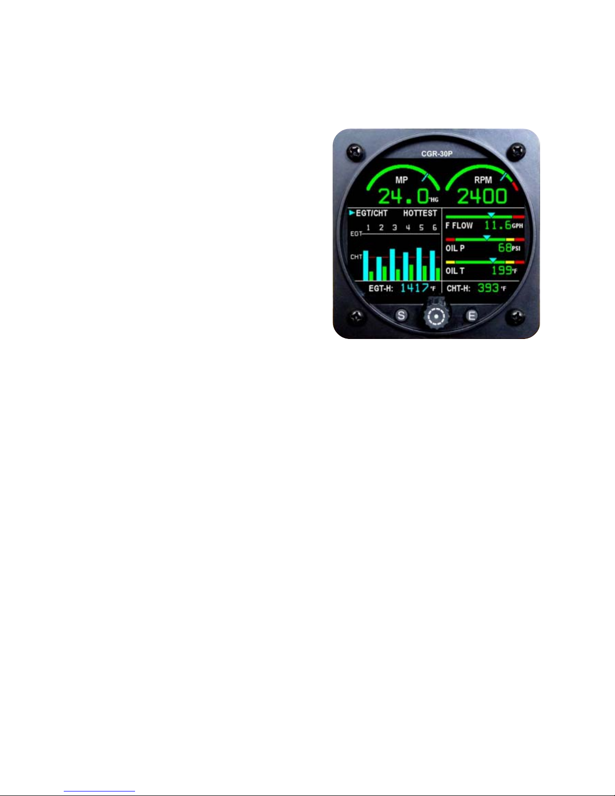
CGR-30P Primary Engine Monitor
FAA-APPROVED POH/AFM Supplement, No. AFM022513, Rev. F
_______________________ _______________ _______________
Airplane Make and Model Reg. Number Serial Number
This supplement must be attached to the FAA
approved Airplane Flight Manual when the aircraft is
modified by the installation of the primary CGR-30P
instrument in accordance with STC SA02283SE.
The information contained herein supplements and/or
supersedes the basic manual only in those areas listed
herein. For limitations, procedures and performance
information not contained in this supplement,
consult the POH or AFM.
LIMITATION(S): No Change
PROCEDURES: The CGR-30P Main Screen
displays the primary engine and aircraft instruments.
This screen is displayed on power-up and is the
screen that should be monitored for most of the flight. Buttons and Knob operate as follows:
(S)creens Button - Switches the display between the various screens.
Rotary Knob (push and turn) - Moves the cursor, selects functions and changes digits.
(E)xit Button- Exits out of a field or screen, returns the display to the Main Screen and
acknowledges blinking digits, annunciators and remote W arning and Caution lights. When Exiting a
field, changes made in that field will remain. When Exiting a screen, if a change has been made, a
pop-up message will give you the option to save or disregard the changes.
Operating Bands and Warnings - To assist the pilot in identifying the current operating band
(green, yellow, red, etc.), the CGR-30P displays the digital value for each function in its appropriate
color. When a function reaches a red or yellow operating band, blinking digits for that function will
alert the pilot. If the remote Warning and Caution lights have been installed, they will also blink
and alert the pilot. To acknowledge the alarm and stop the blinking, press the (E)xit Button while
viewing the Main Screen.
Estimated Fuel - The Fuel Qtys screen displays estimated fuel remaining for each fuel tank. The
digital readout for each estimated fuel level will be displayed in green unless the estimated remaining
for that tank reaches zero, at which time it will be displayed in white. This calculation relies on the
proper setting of the K-Factor and the action of the pilot to match the tank selected on the CGR30P to the tank selected on the aircraft. The “Change To” column in the “Fuel Qtys” screen
allows for transferring fuel from an Aux Tank and adding fuel to a tank. This procedure only
manages the calculated fuel remaining in the instrument, it does not physically transfer fuel in the
aircraft. It is the pilots responsibility to insure the CGR-30P fuel management matches the
management of fuel for the aircraft.
Continued on back...
Electronics International Inc. • 63296 Powell Butte Highway • Bend, OR 97701
www.Buy-Ei.com • (541) 318-6060
If the CGR-30P is setup to receive GPS data, the fuel management screens will provide estimated
data based on the current GPS speed, GPS distance to the way point, the current fuel flow and
the current estimated fuel remaining. This data is used to calculate Time, Fuel Quantity and
Distance information. All calculated data will be displayed in green until 45 minutes or less of
fuel remaining (based on 75% Maximum Continuous Power) is reached, at which time the data
will be displayed in white. If GPS data is not available, the estimated data will be displayed as
“N/A.”
Twin Engine Operation - If the EGT high and low range settings are changed, they should be set
to the same values on both the left and right CGR-30Ps. This will allow the pilot to compare left
and right engine operation.
If the left and right CGR-30Ps are providing fuel predictions (fuel remaining, fuel to destination,
fuel reserve, etc.), the pilot should use the conservative of the two predictions displayed on the
left and right CGR-30Ps.
If cross feeding between right and left fuel tanks is performed, the Fuel Remaining displayed on
the left and right CGR-30P’s will be incorrect, but the total of the left and right fuel readings will
be correct.
Safety - Any instrument can fail at any time. Acquire proper training to safely operate this aircraft
without the use of this instrument. The CGR-30P Operating Instructions must be readily available
in the aircraft. Refer to the Operating Instructions for further operating and safety information.
PERFORMANCE: No Change
LOADING INFORMA TION: No Change
FAA-Approved: ______________________________________ Date: ____________
Manager, Seattle Aircraft Certification Office
 Loading...