

Electronics inc 250-N, 1578, 500-N, 579, 577 Instruction Manual
...
Instruction Manual
Standard Accuracy Series MagnaValves™
For the Following
MagnaVa lve Models
250-N
500-N 579
577 1579
1577 580
578 590
Hybrid Installations
VLP+599-5.0
LP+599-5.0
*Added 1500 Series
16 July, 2002
1578
Electronics Inc.
56790 Magnetic Drive
Mishawaka, Indiana 46545
1-800-832-5653 (Toll Free)
Phone: 1-574-256-5001
Fax: 1-574-256-5222
E-mail: sales@electronics-inc.com
Website: www.electronics-inc.com
Standard Accuracy Series MagnaValves
IM:0072 Revision: G Date: 2/13/13
Made in the USA
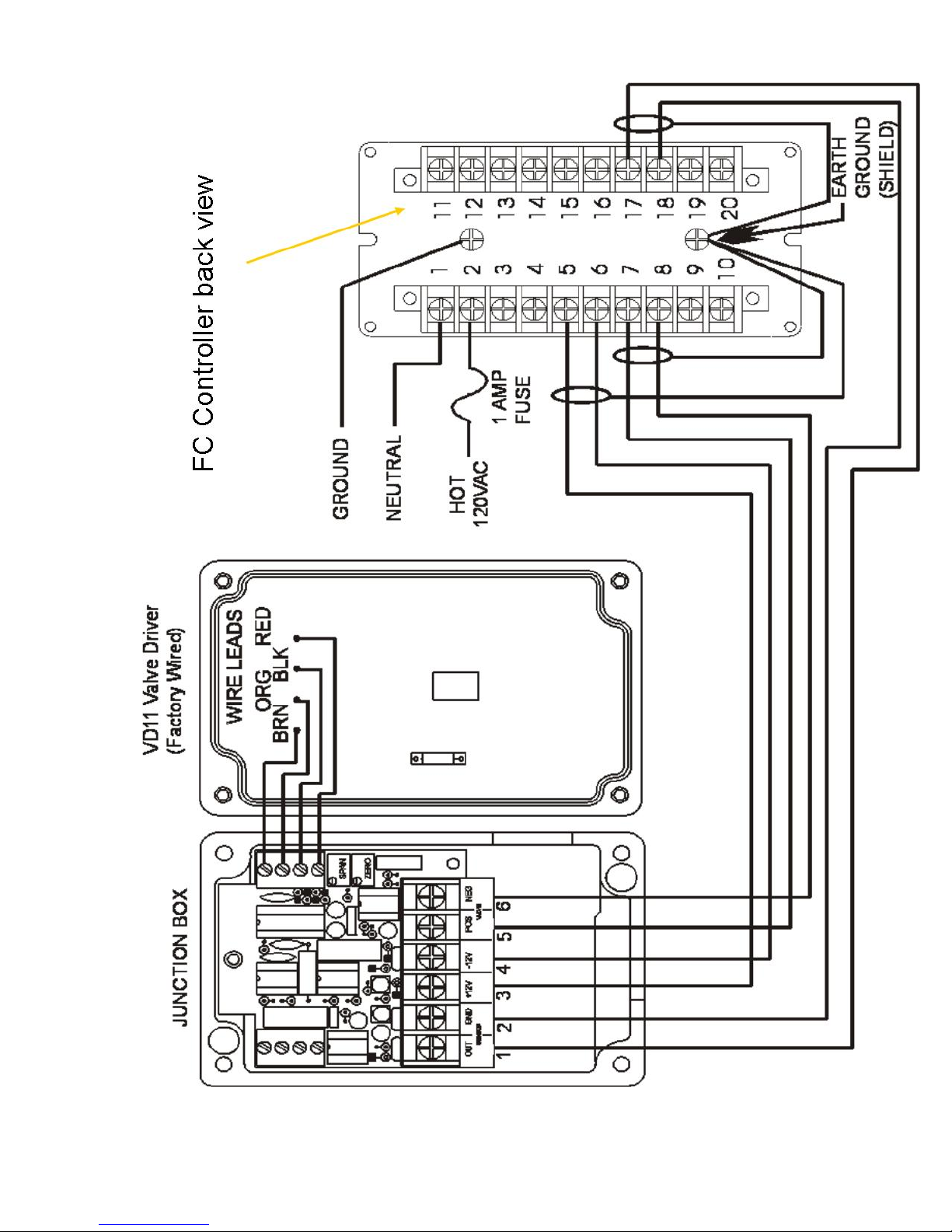
Wiring Diagram
2
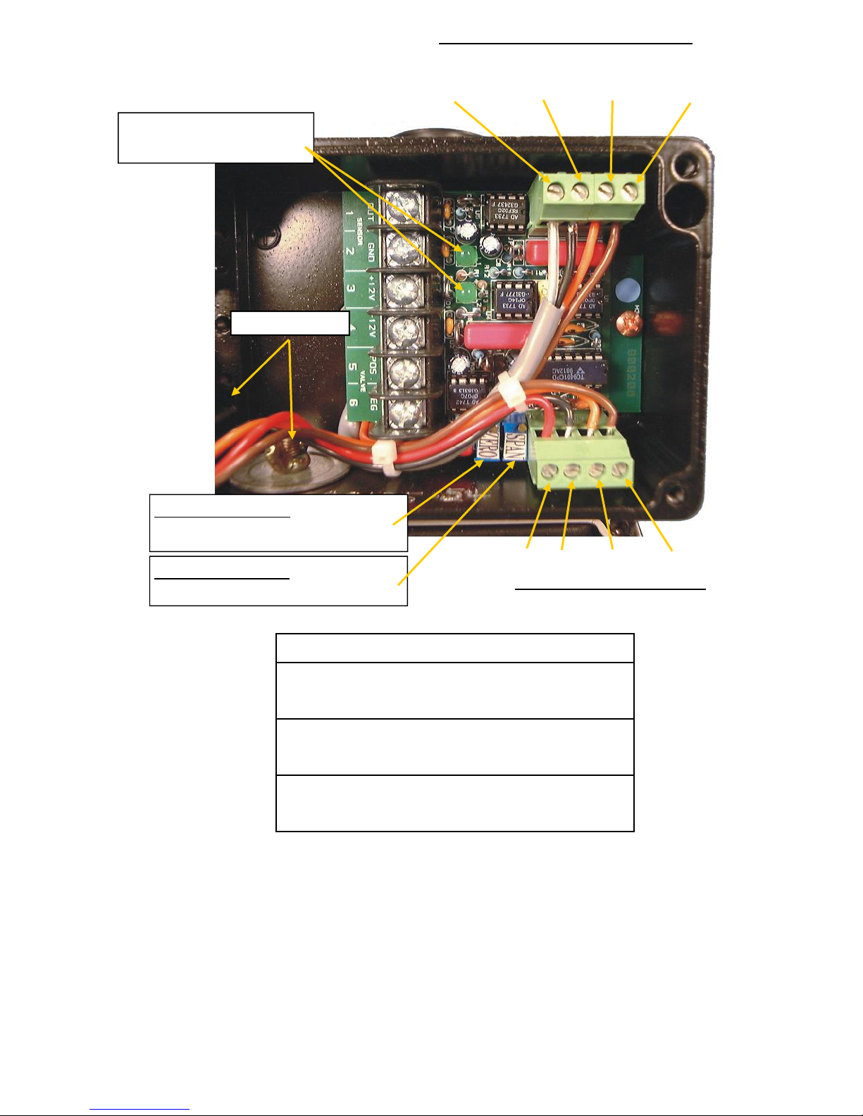
Factory MagnaValve Connections
Sensor wires Power Coils
Two LED’s indicate the
presence of ±12Vdc.
Conduit Ports
White (clear)
Black
Orange
Brown
ZERO Adjustment – Used to set
0 Volts for a no flow condition
SPAN Adjustment – Used to calibrate the maximum flow
Red
Black
Valve Driver Connections
Orange
Brown
Typical Customer wiring connections
Pair 1 White 1. 0-5VDC out
Black 2. 0VDC
Pair 2 Green 3. +12VDC
Black 4. –12VDC
Pair 3 Red 5. (+) MagnaValve
Black 6. (-) MagnaValve
Notes:
1. The Magna valve is calibrated at the factory. A catch and weigh test is recommended during
installation. Make any adjustments for maximum flow using the Span at the Magnavalve only.
2. All cable shields at the valve must be isolated from any part of the valve and machine. The
shields should be terminated at the controller only.
3. A separate conduit for MagnaValve cables must be used to prevent and interference from other equipment. Multiple MagnaValve cables may be routed in the same conduit.
3
 Loading...