

Electronics Diversified Omega 2 User Manual

Control Console
User Manual
Revision 6, January 1999
© 1998, Electronics Diversified, Inc.
070-0130
1

INTRODUCTION
This User Manual is supplied with your system. Copies of this
manual may be obtained from Electronics Diversified, Inc. for a
nominal charge. It is recommended that you copy those portions of
this manual applicable to your present use in the installation,
maintenance or repair and preserve the original in a safe place.
© 1998, by Electronics Diversified, Inc. All rights reserved.
No part of this manual may be reproduced by any means,
graphic, electronic, or mechanical, including photocopying,
recording, taping, or information storage and retrieval systems,
without the express written permission of Electronics Diversified,
Inc., except in connection with installation, operation, repair and
maintenance of Electronics Diversified, Inc. systems.
Omega 2
ABOUT THE OMEGA 2
Omega 2 continues the tradition of a single-scene, pile-on,
performance lighting console designed for 'Hands-On' control of
live performances. The console incorporates four automated
independent fader tracks for simultaneous playback operation of
cue actions. All faders incorporate 'Go' button technology with a
manual override for independent control of any fade action.
The high definition Color Video Display is designed to make it
easy to identify and coordinate information. An independent panel
has manual sliders that are configured in rows to match the VGA
screen layout. Colored indicators mounted above the Bump Buttons
are coordinated with the screen colors for quick identification of
control status.
The Omega 2 gives you the flexibility to achieve the same result
through a variety of screens and methods. For example, you can set
cue levels in the Stage, Preview, Track or Cue List Screens.
By using the remote alphanumeric keyboard, you can label any
recorded Cue, or Submaster group. Channel location, focus area,
type of lighting fixture, color, or special function can be labeled to
assist you in the control function. The label process allows text color
and background changes for increased visual impact. All labels can
be recorded to disk as a special file for independent recall from
stage cues.
HOW TO USE THIS MANUAL
A "Hands On" approach is the best way to master the sophisticated
features of the Omega 2.
For that reason, this manual is set up similar to a mock tutorial.
The chapters correspond to the different screens (Setup, Help,
Stage, Submaster, Playback, Preview, Track, Cue List, Effect,
Patch, Macro, Profile) that you can access on the console.
Each chapter steps you through a series of exercises that shows
you how to use and set the console's features.
There is some repetition between chapters. This is because the
Omega 2 allows you to achieve the same result using a variety of
screens. This flexibility supports faster input and operation because
you can operate the system according to your particular preference
and style.
The detailed Table of Contents helps you quickly locate
instructions for specific routines.
A good way to begin using the Omega 2 is to set aside time to go
through the System Details, Setup and Stage chapters in one sitting.
This will introduce you to the system and provide the context for
moving on to more advanced topics.
2

TABLE OF CONTENTS
Omega 2
SYSTEM DETAILS
Front Panel . . . . . . . . . . . . . . . . . . . . . . . . 4
Control Keys . . . . . . . . . . . . . . . . . . . . . . . 4
Screen Keys . . . . . . . . . . . . . . . . . . . . . . . 5
Action Keys . . . . . . . . . . . . . . . . . . . . . . . . 6
Number Keys . . . . . . . . . . . . . . . . . . . . . . . 6
Selection Keys . . . . . . . . . . . . . . . . . . . . . . 6
Fader Keys . . . . . . . . . . . . . . . . . . . . . . . . 7
Command Keys . . . . . . . . . . . . . . . . . . . . . 7
Rear Panel . . . . . . . . . . . . . . . . . . . . . . . . . 8
Alphanumeric Keyboard . . . . . . . . . . . . . . 8
Manual Slider Control . . . . . . . . . . . . . . . . 9
Making Connections . . . . . . . . . . . . . . . . . 9
Disk Drive Operation . . . . . . . . . . . . . . . . 11
Formatting a Disk . . . . . . . . . . . . . . . . . . 11
SET UP SCREENS
Main Menu . . . . . . . . . . . . . . . . . . . . . . . 12
Setting System Defaults . . . . . . . . . . . . . 12
System Menu . . . . . . . . . . . . . . . . . . . . . . 13
Cues Menu . . . . . . . . . . . . . . . . . . . . . . . . 13
Submaster Menu . . . . . . . . . . . . . . . . . . . 14
Patch Menu . . . . . . . . . . . . . . . . . . . . . . . 14
Front Panel Menu . . . . . . . . . . . . . . . . . . 14
Save To Disk Menu . . . . . . . . . . . . . . . . . 15
Load From Disk Menu . . . . . . . . . . . . . . . 15
Print Functions Menu . . . . . . . . . . . . . . . . 16
Clear Menu . . . . . . . . . . . . . . . . . . . . . . . . 16
Time Functions Menu . . . . . . . . . . . . . . . 16
Peripherals/Utilities Menu . . . . . . . . . . . . 17
Using the Help Window . . . . . . . . . . . . . . 17
STAGE SCREEN
Preview. . . . . . . . . . . . . . . . . . . . . . . . . . . 18
Setting Levels from the Keypad . . . . . . . 20
Controlling Levels with the Wheel . . . . . . 22
Setting Levels with the Sliders . . . . . . . . . 23
Setting Levels in Combination . . . . . . . . . 24
Select & Control All Channels at Once . . 26
Recording Cue Levels . . . . . . . . . . . . . . . 28
Cue Attributes . . . . . . . . . . . . . . . . . . . . . 29
Cue Labeling . . . . . . . . . . . . . . . . . . . . . . 31
Time Controls . . . . . . . . . . . . . . . . . . . . . . 31
Delay Times . . . . . . . . . . . . . . . . . . . . . . . 32
Labeling the Stage Screen . . . . . . . . . . . 33
Setting Blank Channels . . . . . . . . . . . . . . 35
Recording Without Submasters . . . . . . . . 36
Submasters . . . . . . . . . . . . . . . . . . . . . . . 36
SUBMASTERS
Recording Submasters . . . . . . . . . . . . . . 37
Assigning Times to a Submaster . . . . . . . 38
Selecting the Submaster Mode . . . . . . . . 39
Page Numbers and Labels . . . . . . . . . . . 40
Merge & Insert Commands . . . . . . . . . . . 41
Copy Levels From One Submaster
to Another . . . . . . . . . . . . . . . . . . . . . . 42
SUBMASTER PLAYBACK
Running Playbacks . . . . . . . . . . . . . . . . . 43
FADER OPERATIONS
Running a Fader . . . . . . . . . . . . . . . . . . . 46
Loading a Fader . . . . . . . . . . . . . . . . . . . . 47
Take Control of a Fade . . . . . . . . . . . . . . 47
Wheel Control of a Fader . . . . . . . . . . . . 48
Manual Control of a Fader . . . . . . . . . . . . 49
Manual Control of a Split Fade . . . . . . . . 50
Multipart Cues . . . . . . . . . . . . . . . . . . . . . 50
Multiple Active Faders . . . . . . . . . . . . . . . 53
ADVANCED CUE FEATURES
Creating a Temporary Cue . . . . . . . . . . . 54
Modifying Cues . . . . . . . . . . . . . . . . . . . . 55
Previewing a Temporary Fade . . . . . . . . 56
PREVIEW SCREEN
Using the Preview Screen . . . . . . . . . . . . 57
Merge & Insert Commands . . . . . . . . . . . 58
Copying Cue Levels . . . . . . . . . . . . . . . . . 58
TRACK SCREEN
Using the Track Screen . . . . . . . . . . . . . . 59
Screen Positioning . . . . . . . . . . . . . . . . . . 59
Editing Levels on Screen . . . . . . . . . . . . . 60
Cue Only Feature . . . . . . . . . . . . . . . . . . . 61
CUE LIST
Using the Cue List Screen . . . . . . . . . . . . 62
Changing Times and Cue Names . . . . . . 62
Linking Cues . . . . . . . . . . . . . . . . . . . . . . 63
Manual Fader Control . . . . . . . . . . . . . . . 63
Macro Activation in a Cue . . . . . . . . . . . . 64
Effect Activation in a Cue . . . . . . . . . . . . . 64
EFFECT SCREEN
Using the Effect Screen . . . . . . . . . . . . . . 65
Positioning the Cursor & Setting Levels . 65
Effect Record Window . . . . . . . . . . . . . . . 67
Setting the Step Time . . . . . . . . . . . . . . . 68
Submaster Control . . . . . . . . . . . . . . . . . . 69
Master Channel . . . . . . . . . . . . . . . . . . . . 69
Testing an Effect . . . . . . . . . . . . . . . . . . . 69
Chase Attributes . . . . . . . . . . . . . . . . . . . 70
PATCH SCREEN
Using the Patch Screen . . . . . . . . . . . . . . 72
Patch By Dimmer . . . . . . . . . . . . . . . . . . 72
Position Control Keys . . . . . . . . . . . . . . . 74
Parked Dimmers . . . . . . . . . . . . . . . . . . . 75
Unpatch Dimmers . . . . . . . . . . . . . . . . . . 76
Unity Patch . . . . . . . . . . . . . . . . . . . . . . . . 77
Assigning Profiles to Dimmers . . . . . . . . 77
Bypass Grand Master . . . . . . . . . . . . . . . 78
MACRO SCREEN
Viewing Macros . . . . . . . . . . . . . . . . . . . . 79
Creating Macros . . . . . . . . . . . . . . . . . . . . 79
PROFILE SCREEN
Using the Profile Screen . . . . . . . . . . . . . 81
Selecting and Setting Modes . . . . . . . . . . 81
ACCESSORIES
Remote Record . . . . . . . . . . . . . . . . . . . . 82
Remote Video . . . . . . . . . . . . . . . . . . . . . 82
Keyboard . . . . . . . . . . . . . . . . . . . . . . . . . 82
Designers Remote . . . . . . . . . . . . . . . . . 82
Hand-held Remote . . . . . . . . . . . . . . . . 83
Printers . . . . . . . . . . . . . . . . . . . . . . . . . . 83
MIDI . . . . . . . . . . . . . . . . . . . . . . . . . . . . 84
SMPTE (Timed Actions) . . . . . . . . . . . . . 84
Common Questions . . . . . . . . . . . . . . . . 85
SPECIFICATIONS
Chassis . . . . . . . . . . . . . . . . . . . . . . . . . . 87
Front Panel . . . . . . . . . . . . . . . . . . . . . . . 87
Channel Slider Board . . . . . . . . . . . . . . . 88
Slider Stand Assembly Instructions . . . . 89
SHOW CONTROLLER
Remote Show Controller . . . . . . . . . . . . . 90
Front Panel . . . . . . . . . . . . . . . . . . . . . . . 90
Using the Timed Actions Screen . . . . . . 91
Selecting the Time Source . . . . . . . . . . . 91
LCD Display . . . . . . . . . . . . . . . . . . . . . . 91
SERVICE
Support Information . . . . . . . . . . . . . . . . 93
Registration . . . . . . . . . . . . . . . . . . . . . . 95
3

SYSTEM DETAILS
Omega 2
FRONT PANEL
The Omega 2 is a microprocessor-based control system with all
operational instruction sets and controls routines embedded in
read-only memory. The control console front panel allows access to
these instructions and routines through key selections. All key
selections are echoed on the system command line located at the
bottom left of your monitor.
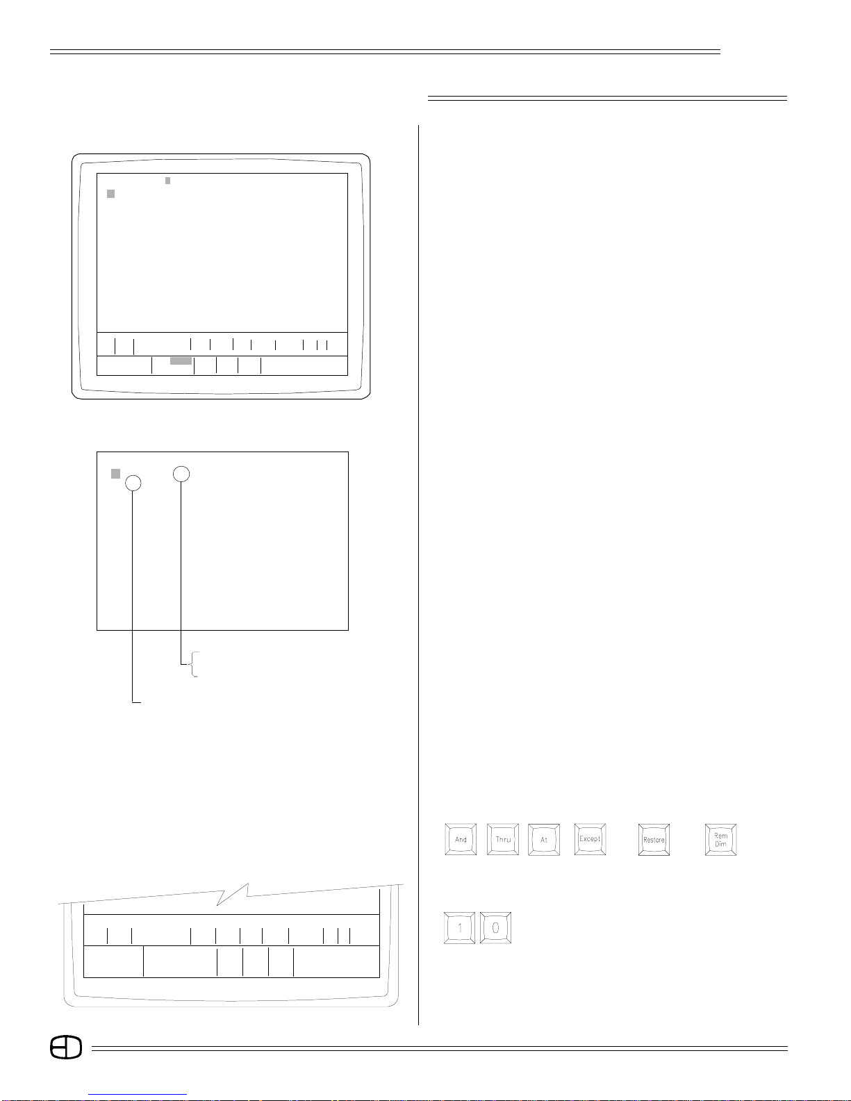
Here is an overview of the front panel controls.
1
5
6
1. FADER CONTROL BUTTONS:
Select active fader.
Allow manual takeover of automated fades.
Clear active cue from the fader.
2. MANUAL FADER CONTROLS:
Manually control cues.
Adjust fade level up or down from the capture point.
Offer Grand Master proportional control.
3. CONTROL KEYS:
Select active display screens for monitor.
Access channels and level information.
Organize recording, playback and editing sequences.
Start and stop automated features.
4. ENCODER WHEEL:
2
3
4
Adjusts selected channel levels proportionally.
Accelerates or slows fade times proportionally.
5. KEY SWITCH:
Controls access to power.
Controls access to record feature.
6. DISK DRIVE (located on right
Side):
Off-line storage for recorded information.
Off-line storage of custom configurations.
Screen Keys
Action Keys
Command
Keys
Fader Keys
Number Keys Selection Keys
Screen Keys
CONTROL KEYS
The primary access to the control system is through the keypad
controls on the front panel of the console. The keypads are grouped
together under common control headings for ease of operation.
There are six groups:
Screen Keys
Action Keys
Number Keys
Selection Keys
Fader Keys
Command Keys
The general titles for the grouping of keys indicate their functions.
The natural progression for the commands from the keypads is from
left to right.
4
SYSTEM DETAILS
Omega 2
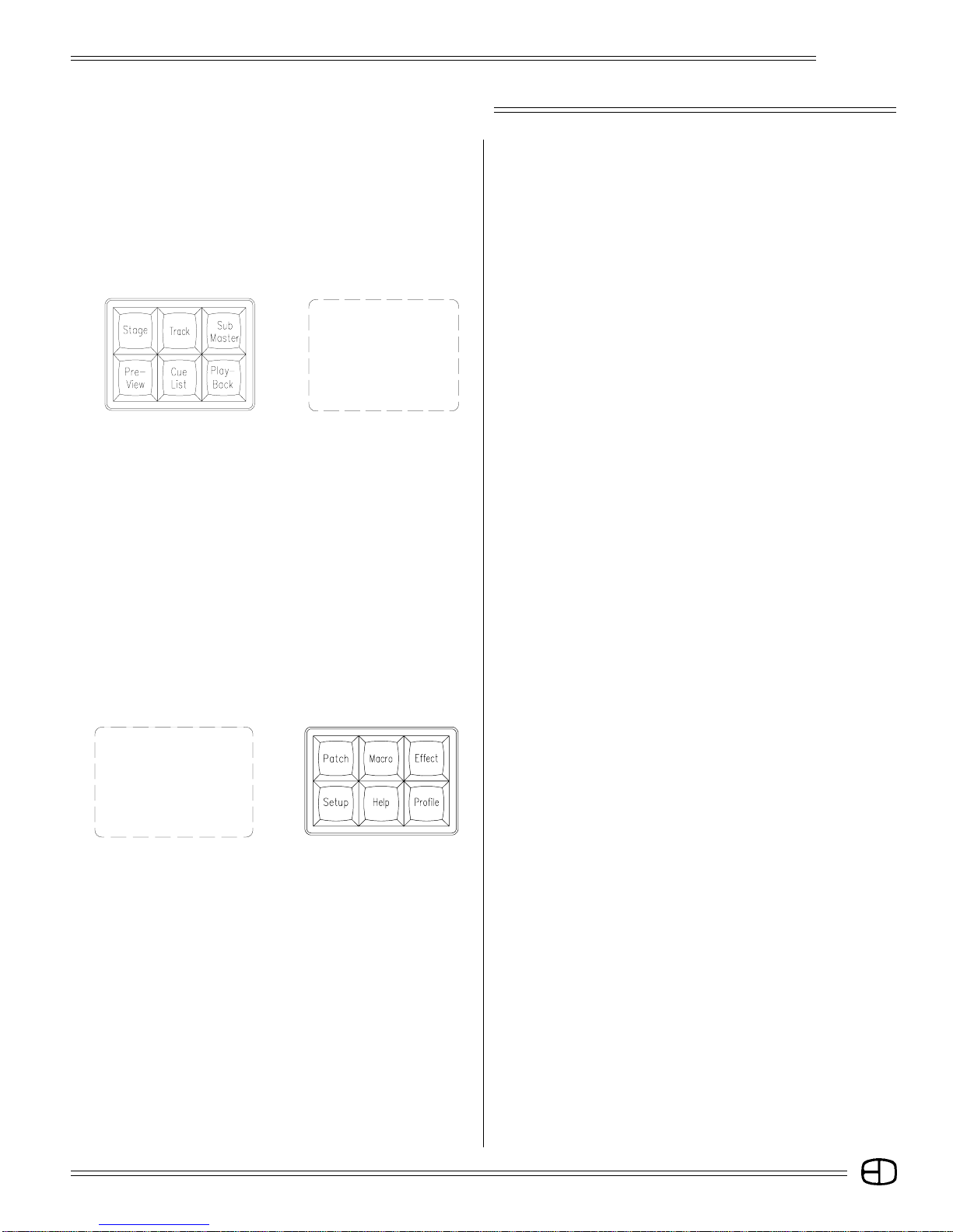
SCREEN KEYS
The Screen Keys access the primary displays of the control
console. The control 'point of view' can be changed at any point by
selecting a different Screen Key. Changing screens does not affect
or stop an action that was set in place on a previous screen. Screen
Keys on the top left deal directly with organization and playback,
while Screen Keys on the top right control access and special
information in the system.
STAGE:
This screen shows channels with levels from the various sources.
Also shown is information on the cue on stage and the two
following. Cues and subs can be recorded or rerecorded and cue
times can be changed on this screen.
TRACK:
This screen shows the cues and channels in a spreadsheet
format. Cue levels can be edited blind in this screen.
SUBMASTER:
This screen shows the contents of submasters. A submaster's
levels and times can be edited blind in this screen. New submasters
can also be recorded.
PREVIEW:
This screen shows the contents of cues. A cue's levels and
attributes can be edited blind in this screen. New cues can also
be recorded.
CUE LIST:
This screen shows the list of the cue times and attributes which
can be edited.
PLAYBACK:
This screen shows a listing of submasters and the current page
that is active. Times can be changed and handles can be forced
to new pages. The current output level for the Submaster is
displayed.
PATCH:
This screen shows the system patch by dimmer. Dimmers can be
assigned to channels with proportional levels and profiles.
Dimmers can be parked at levels, or assigned to submaster
handles.
MACRO:
This screen shows the contents of the Macro. Macros can be
created and edited here.
EFFECT:
This screen will show Effects' steps and times. Steps can be
added, inserted and deleted.
A second press displays the TIMED ACTIONS screen. This
screen shows actions that can be started by SMPTE, a timer, or
by the clock.
SETUP:
This screen shows the user-definable parameters. These
configurations can be set on this screen.
HELP:
Accesses the Help window at the bottom of each screen. Active
keys and instructions for each key are displayed.
PROFILE:
The Profile screen shows preheats and other custom profiles
which can be edited and assigned in Patch.
5
SYSTEM DETAILS
Omega 2
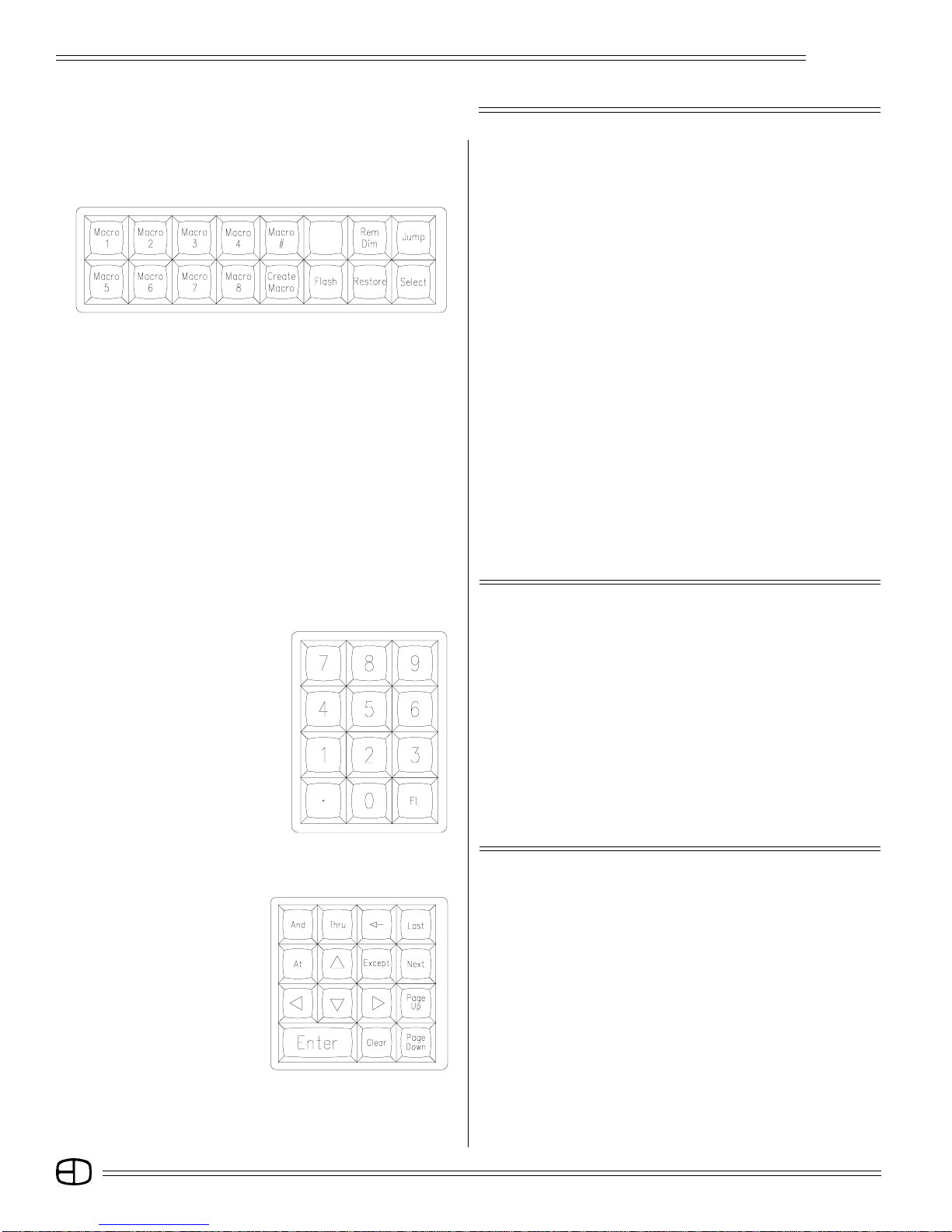
ACTION KEYS
Action Keys allow specific functions to be executed. They are
short cuts to quickly establish a condition or a result.
MACRO 1-8:
Direct access to the first eight Macros.
MACRO #:
Addresses Macros greater than 8.
CREATE MACRO:
Opens or closes a Macro for live recording.
FLASH:
Bounces between two levels assigned in 'Setup'. It is useful in
checking lights before a show.
REM DIM (Remainder Dim):
Forces all unaddressed levels to '0.'
RESTORE:
Returns screen to conditions before last Enter. Restore is
essentially an "undo" feature.
JUMP:
Moves the cursor to the next field on the screen.
SELECT:
Allows you to select mode options while in the Record Window,
Patch Screen, or Playback Screen.
NUMBER KEYS
Number Keys are the primary way to enter values into the Cues,
Times, Submasters and Effects. Number Keys are always reflected
on the system Command Line.
NUMBER KEYS:
Make a selection by entering the value on the Command Line.
DECIMAL KEY:
Used to insert between whole number cues or to identify tenth of
seconds.
FL KEY(Full) :
Assigns a value of 100%.
SELECTION KEYS
TRANSITION KEYS:
Bridge between channel selections and level setting. These
include [AND], [THRU], [AT], and [EXCEPT].
CURSOR POSITION KEYS:
These are designated by arrows and allow you move around the
screen quickly. They include [UP], [DOWN], [LEFT], or [RIGHT].
GENERAL POSITION KEYS:
Move the screen in block movements one block at a time. These
keys include [PAGE UP], [PAGE DOWN], [NEXT], and [LAST].
CONFIRMATION KEYS:
Deal directly with the Command Line instruction by accepting
the statement [ENTER], clearing the line [CLEAR], or eliminating
one item at a time from the line [BACKSPACE].
6

SYSTEM DETAILS
Omega 2
FADER KEYS
Fader keys are the primary way to store information for playback.
Fader keys coordinate with the Fader display on the Stage, Preview,
Submaster, Track, Playback and Cue List screens. They update you
on the latest conditions of playback. Fader keys can start, pause,
stop, or allow manual control for any action.
FADE TAKE:
Gives control of the selected faders to the manual fader controls.
LOAD:
Loads a cue on the selected fader.
STOP/REV:
Stops all faders in progress. A second press backs up one Cue.
GO:
Starts selected faders.
COMMAND KEYS
Using the Command Keys, you can record, modify record, or
delete items called out on the Command Line. You can select the
functions for Cues, Submasters or Times, as directed.
MERGE:
Merges a Cue and/or a Submaster into an established look on a
'highest takes precedence' basis.
CAPTURE:
Captures channels to establish a temporary cue.
(See page 54).
INSERT:
Inserts a Cue and/or a Submaster into an established look on a
'last action' basis.
GO TO CUE:
Routes Stage display to new position with cue action in Fader.
RECORD:
1st key used in the Record process.
DELETE:
Deletes Cues, Submasters.
UPDATE:
Automatically records modified levels into existing cues.
CUE ONLY:
In Tracking Mode, levels are modified for only one cue. Resets
previous levels for next cue without tracking.
TIME:
Used in Record process to assign Fade times on cue list.
CUE:
Accesses Cue memories.
SUBMASTER:
Accesses Submaster memories.
7
SYSTEM DETAILS
8
2
3
15
6
4
79 13
10
Omega 2
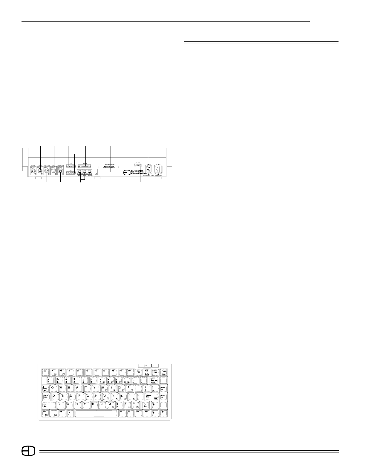
REAR PANEL
Located on the rear of the console are the control outputs as well
as the power input. An explanation of each output connector is
described below. Control cables furnished with the console mate
these outputs to the system connection plates in your facility. There
are two types of connectors on the output panel: heavy duty XLR
connectors and standard computer grade 'D' style connectors.
All XLRs are keyed, locking connectors. Position the connector
carefully at the receptacle, rotate until it mates with the key, then
insert it. When inserting 'D' series connectors, tighten the thumb
screws on the male end to insure proper connection.
Do not force connectors into position.
12
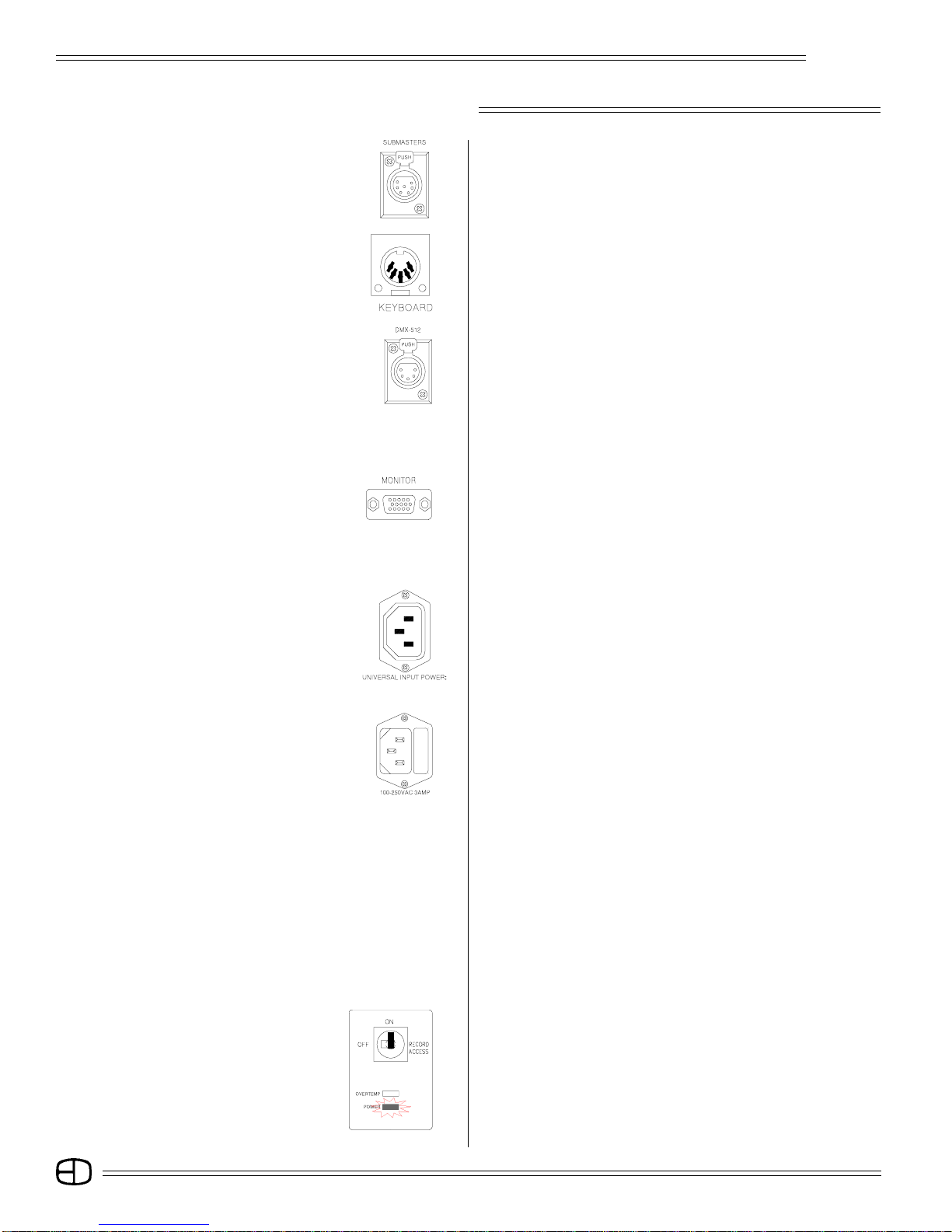
01. DMX OUTPUT:
(Dimmers 1-512) (5-Pin XLR)
02. HAND-HELD REMOTE:
(4-Pin XLR)
03. MANUAL SLIDERS INPUT:
(7-PIN XLR)
11
04. TIMED ACTIONS INPUT:
(optional) (3-Pin XLR)
05. REMOTE VGA MONITOR:
(6-Pin XLR)
06. AUXILIARY SERIAL PORTS:
(DB15)
07. MIDI IN & OUT:
(optional)
08. PRINTER OUTPUT:
(DB25)
09. ALPHANUMERIC KEYBOARD:
10. PERSONALITY MODULE:
(software update access)
11. VGA/SVGA MONITOR:
(D15, 3-row, VGA standard)
12. CONVENIENCE OUTLET:
( 120VAC/300 watts max.)
13. POWER INPUT FUSE BLOCK:
(92 to 235 VAC, 47/64 Hz, 3 Amp)
ALPHANUMERIC KEYBOARD
The Omega 2 is designed to operate with any standard IBM PC/
AT keyboard. The Omega 2 is shipped with a remote keyboard as
standard equipment.
Alphanumeric text can be entered into the Stage Screen from this
remote keyboard. Entered text can be labels describing the type or
focus of the lighting instruments, or comments about the area of
focus or position on stage.
If you encounter problems with using any keyboard, please
contact the factory, as some manufacturers of AT aftermarket
keyboards have been known to be incompatible.
8

SYSTEM DETAILS
1
2
Omega 2
MANUAL SLIDER CONTROL
The Omega 2 Console supports an independent panel of 120
manual sliders. Each slider is equipped with a tricolor LED to
indicate the channel status and a Bump Button for direct output.
The sliders allow direct 'hands on' control of 120 control channels
for level setting or overriding an established level. The sliders can
also offer direct dimmer output control for stand-alone or emergency
operation by positioning the Output Mode Selection Switch (see #7
below) at the top of the independent panel.
60° Configuration
3
1. REMOTE 120-CHANNEL MANUAL SECTION.
2. INDIVIDUAL CHANNEL STATUS LED's.
3. INDIVIDUAL CHANNEL BUMP BUTTONS.
4. MANUAL CHANNEL SLIDERS.
4
5. OUTPUT CONNECTOR TO CONSOLE:
(7-Pin XLR)
6. LOW VOLTAGE POWER CONNECTOR:
(12 VDC / 500MA)
7
6
5
9
8
7. THREE-POSITION OUTPUT SELECTOR SWITCH:
(Submasters / Off / Backup)
8. OUTPUT INDICATORS:
(Power / Data)
9. OUTPUT CONNECTOR TO DIMMER BANK:
Top of Panel
(DMX 5-Pin XLR)
MAKING CONNECTIONS
Like all microprocessor-based controls, the Omega 2 is sensitive
to power fluctuations on standard power lines. The console should
be plugged into an isolated circuit with a full equipment ground. For
best results, the console should be connected to an uninterrupted
power supply (UPS), or at a bare minimum, a high quality power
conditioner.
Do not plug the console into the same outlet as motor or SCRcontrolled devices.
The steps below will guide you through the first power-up exercise
of the Omega 2 Console.
STEP #1:
Position the control console on a flat surface. The key position in
the upper right corner should be Off.
Do not connect the power cable at this time.
STEP #2:
If you're using a manual control with stand, assemble the stand
according to the instructions on page 89.
Determine if the 30-degree or the 60-degree angle of operation
is best for the site. When assembled, position near your control
30° Configuration
console.
STEP #3:
Locate the 7-pin XLR control cable. Identify the keyed position on
both the cable connector and the chassis-mounted connection
point on the top rear of the manual stand. Carefully insert the 7-
pin XLR cable into the connector labeled "Console."
9
SYSTEM DETAILS
Omega 2
STEP #4:
Insert the other end of the 7-pin XLR cable to the connector on the
back of the console labeled 'Submasters.'
STEP #5:
Locate the remote alphanumeric keyboard. Identify the keyed
position on the connector, and match it to the connector on the
rear panel of the console labeled 'Keyboard.' Position the keyboard
in front of the manual section.
STEP #6:
Connect the 5-pin XLR cable into the DMX-512 output port on the
rear of the console. Connect the opposite end to the control
connection plate labeled DMX-512 which goes to the system
dimmers.
STEP #7:
Position the SVGA monitor adjacent to the console. Connect the
VGA cable male end with the (15-pin 'D') connector to the rear of
the monitor. Use the captive thumb screws to tighten the
connection.
STEP #8:
Connect the other male end of the VGA cable to the console video
output labeled 'Monitor.' Use the captive thumb screws to tighten
the connection.
STEP #9:
Connect the recessed female power cord to the rear of the SVGA
monitor.
STEP #10:
Connect the male end of the monitor power cord to the monitor
convenience outlet located on the rear of the console (Item 12,
page 8).
STEP #11:
Connect the male end of the console power cord to a line voltage
outlet (120 VAC, U.S. version or 220 VAC, export version).
STEP #12:
Connect the female end of the power cord to the rear of the
console (Item 13, page 8).
STEP #13:
Check each connection to insure correct mating. If all connections
are correct, remove the cardboard from the system disk drive,
and insert the formatted disk shipped with the console. If
necessary, review Disk Drive Operation, page 11, for proper
orientation of the system disk prior to insertion.
STEP 14:
You are now ready to power up!
Insert the key into the top position on the front panel. Turn the key
clockwise to the first position.
The POWER light under the key position should come on. In
addition, the tricolored LEDs under the Bump buttons will cycle.
STEP #15:
Switch on the monitor. The monitor power LED should illuminate.
The Stage Screen should be displayed. Use the monitor controls
to position the image in the center of the display screen. Expand
the image to fill the screen. Do not fill the entire screen, because
you want the console Command Line to appear below the brown
border on the left side.
The console is ready to operate.
10
SYSTEM DETAILS
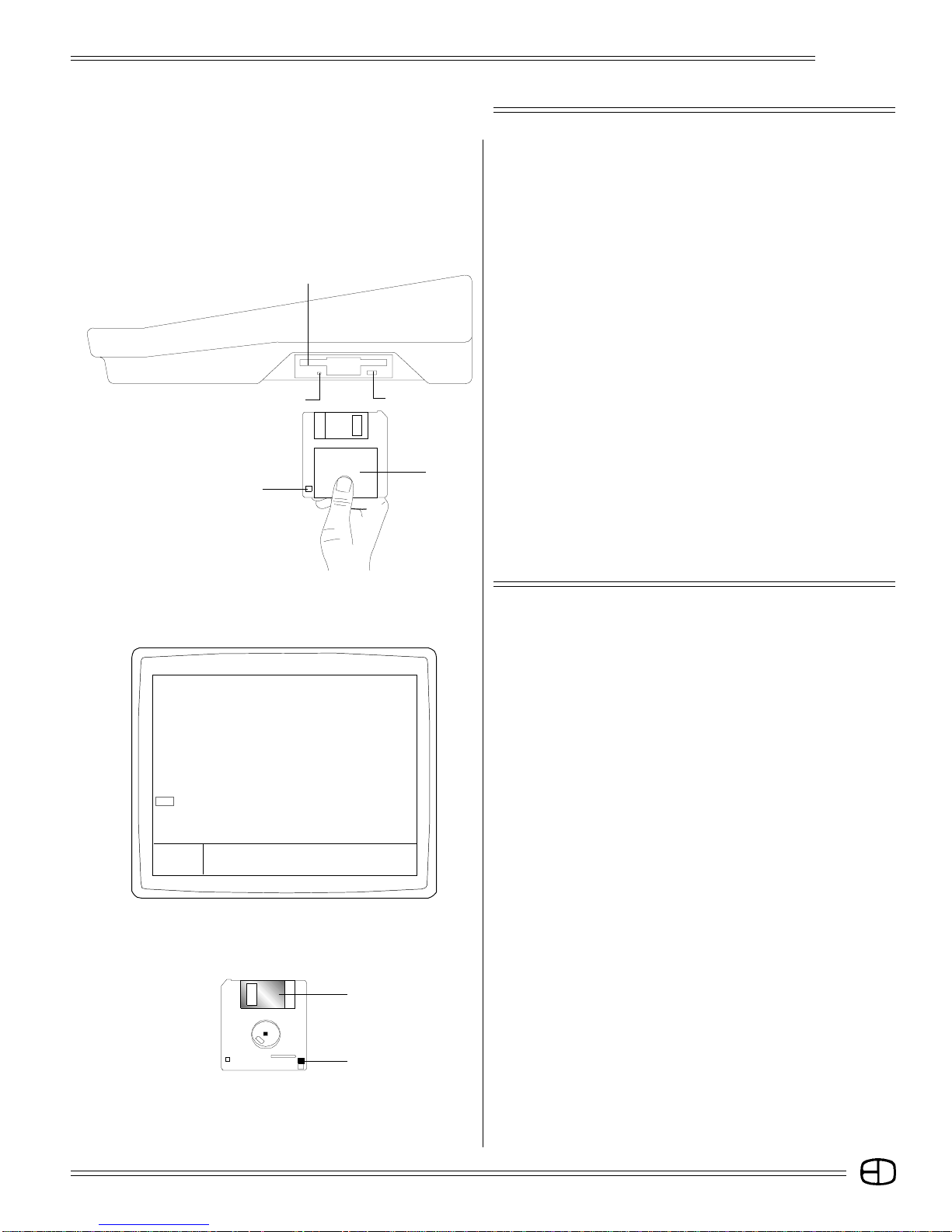
Disk Drive
Indicator Light
Write-protect Tab
Eject Button
3.5" Disk
Omega 2
DISK DRIVE OPERATION
The Omega 2 Control Console is a disk-based control system. All
control information set in place by the operator is automatically
saved in battery-backed random access memory inside the console.
In addition, the information can be saved and stored off-line for
future use on a 1.44MB, 3.5" high-density disk. The disk drive is
located on the right side of the console.
Access to the disk drive features is available through menu
selections on the Setup Screen. Follow the simple procedures
outlined below to insure proper operation.
DISK HANDLING PROCEDURE:
DISK DRIVE: 3.5" IBM format, 1.44MB. Disks must be formatted by
the Omega 2 console before use.
Insert the disk as illustrated. Do not force it into the drive. If the
disk will not insert easily, it is not correctly oriented.
To eject the disk, push the small button on the disk drive.
To protect your data:
Do not expose disks to high temperatures.
Do not store disks near magnetic fields.
Do not eject a disk while the disk drive indicator light is on.
This could result in loss of data or incomplete loading of a show.
Wait until the indicator light goes off before ejecting.
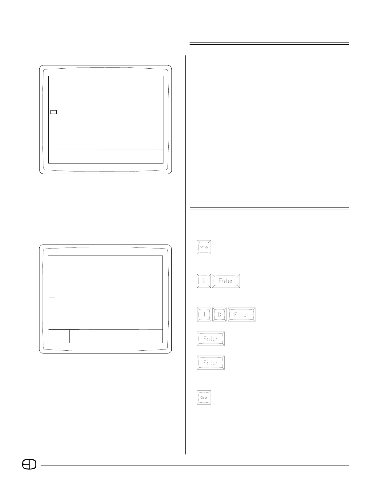
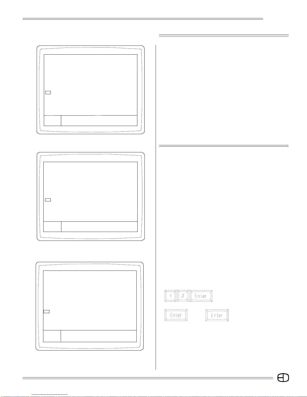
SETUP Version 1.22 Grandmaster FL 9:01:00
PERIPHERALS/UTILITIES
1> Return to main menu
2> Designers remote . . . . . . . . . . . . Yes
3> Hand held remote . . . . . . . . . . . . . Yes
4> Smpte input . . . . . . . . . . . . . . . . . No
5> Midi input/output . . . . . . . . . . . . . No
6> Device ID for Midi . . . . . . . . . . . . . . 0
7> Debug value . . . . . . . . . . . . . . . . . 0
8> SubCommander page . . . . . . . . . . . . 1
9> SubCommander playback . . . . . . . . 1
10> Remote record to SubCommander
11> Format disk
Enter:
ñ
Are you sure?
Metal Flap
Write-protect Tab
FORMATTING A DISK
INSERT DISK TO BE FORMATTED INTO DISK DRIVE:
Press [SETUP]
The Main Menu will appear on the screen.
SELECT PERIPHERALS / UTILITIES MENU:
Press [1] [1] [ENTER]
The Peripherals/Utilities Menu will appear on the screen.
SELECT FORMAT DISK:
Press [1] [1] [ENTER]
The Command Line will respond with "Are You Sure?"
Press [ENTER] again. The console will erase any information on
the disk and format the disk for use with the console.
When completed, the command line will prompt "Format Complete."
Press any key to select the next display.
WRITE PROTECTION:
Write protection locks the disk, preventing alteration of stored
data. To write-protect the disk, orient the diskette so that the round
metal circle is pointed toward you.
If the write-protect tab, located in the lower right-hand corner, is
closed, the disk is not write protected. If the tab is open, the disk is
protected, and no new data can be recorded. Disks should be
double-sided, MF2-HD equivalent. Two non-formatted disks are
supplied with the Omega 2 console.
Disks may be purchased from EDl (Part#119-0058) or any computer
supply house.
11
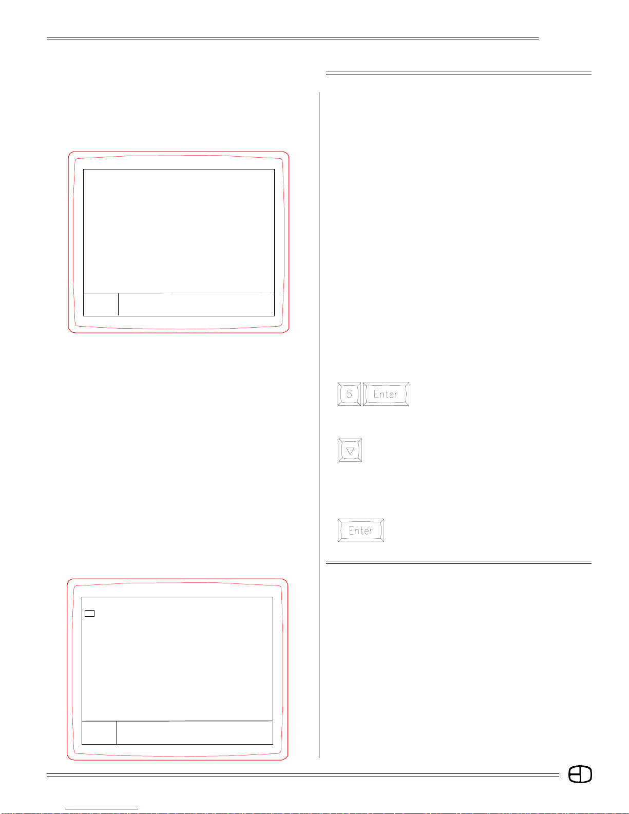
SETUP SCREENS
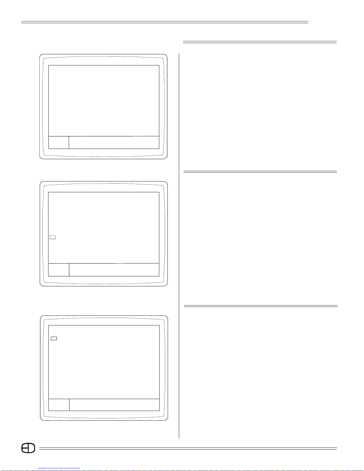
SETUP Version 1.22 Grandmaster FL 9:01:00
MAIN MENU
1> System
2> Cues
3> Submaster
4> Patch
5> Front Panel
6> Save to Disk Functions
7> Load from Disk Functions
8> Print Functions
9> Clear Functions
10> Time Functions
11> Peripherals / Utilities
Enter:
〉
Screen Colors:
Titles . . . . . . . . . . . . . . . . . . . . . . . . . . . . . . . . . . . . . . . . . . . . . . . . . . . . . . . . . . . . Blue
Prompts . . . . . . . . . . . . . . . . . . . . . . . . . . . . . . . . . . . . . . . . . . . . . . . . . . . . . . . . . White
Omega 2
MAIN MENU
Each subject listed on the Setup Main Menu allows you to
configure or set defaults that affect the consoles operation. Some
of the defaults are designed to reduce keystrokes while others set
conditions for operation.
To view or change a category on a Menu, follow the procedure
outlined in the steps below:
A: Type the number, or move the cursor to the number next to the
topic and press [ENTER].
B: To toggle a Yes / No response, press [ENTER].
C: To change or set a value on the highlighted topic, type the new
number, press [ENTER].
D: To return to the Main Menu, press the [CLEAR] key.
When changing or setting new values, the Command Line may
prompt with an Are You Sure statement This prompt requires
[ENTER] to be pressed a second time to confirm the change.
Take a few moments to review each of the 11 menus listed under
the Main Menu. Macros can be used to access common selections
that change regularly.
The following pages highlight and explain each of the control
options settings.
SETUP Version 1.22 Grandmaster FL 9:01:00
CLEAR FUNCTIONS
1> Return to main menu
2> Clear cues
3> Clear submasters
4> Clear patches
5> Clear effects
6> Clear macros
7> Clear handle text
8> Clear smpte
9> Default profiles (linear)
10> Default setup
11> CLEAR ALL
Enter:
〉 Are You sure?
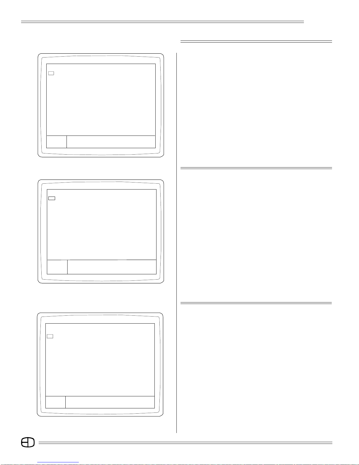
SETTING SYSTEM DEFAULTS
SELECT THE MAIN MENU IN THE SETUP SCREEN:
Press
The Main Menu will appear.
ESTABLISH ALL DEFAULT SETTINGS FOR THE CONSOLE:
Press
The Clear Functions Menu will appear.
SELECT THE DEFAULT SETUP CONDITION:
Press
The cursor is positioned on Default
Setup.
Press
The Command Line will prompt "Are You Sure?"
Press
The Command Line will prompt "Setup Cleared."
RESTORE MAIN MENU:
Press
The Main Menu will appear on the Screen.
If the system dimmer count is the same or less than the system
channel count, there will be a Unity Patch of one dimmer to one
channel. Dimmers beyond the system channel count will not be
addressed without an assigned patch from the Patch Display.
(For information about the Patch procedure and the Patch Display,
see page 77).
12
SETUP SCREENS
SETUP Version 1.22 Grandmaster FL 9:01:00
SYSTEM
1> Return to main menu
2> Set channels to blank
3> Display name and link in TRACK . . . . . . . . . . Yes
4> Levels shown in hex . . . . . . . . . . . . . . . . . . . No
5> Recording in fast mode . . . . . . . . . . . . . . . . . No
6> Goto Cue aborts all fades . . . . . . . . . . . . . . . Yes
7> Flash lower intensity . . . . . . . . . . . . . . . . . . . 10
8> Flash upper intensity . . . . . . . . . . . . . . . . . . . 80
9> Flashing rate. . . . . . . . . . . . . . . . . . . . . . . . . 01
10> Number of dimmers . . . . . . . . . . . . . . . . . . 512
11> Number of channels . . . . . . . . . . . . . . . . . . 120
12> Title in Stage Screen . . . . . . . . . . . . Omega 2
13> Time for Goto Cues . . . . . . . . . . . . . . . . . . . 0
14> Total units . . . . . . . . . . . . . . . . . . . . . . . . 238
Enter:
〉
Omega 2
SYSTEM MENU
The System Menu allows access to setup conditions that affect
how the control information is processed. The number of dimmers
and control channels is set from this menu. The list below reviews
each category.
01. Returns to Main Menu.
02. Allows user to blank selected channels for display.
(To set blank channels, refer to Stage Screen, page 35.)
03. Removes columns which display the cue name and link
characteristics from the Track screen.
04. When selected, converts all output levels to 256-step resolution.
05. Reduces/increases key hits for recording.
06. Goto Cue will affect all faders, not just the one selected.
07. Sets the lowest level for Flash.
08. Sets the highest level for Flash.
09. Sets the rate or timing for the number of flashes per minute.
10. Sets the system capacity for dimmer address.
11. Sets the system capacity for the number of channels displayed
and addressed.
12. When selected, keyboard may enter alphanumeric label for
display on Stage screen.
13. Sets default fade time for go-to-cue selections.
14. Reflects available memory units at all times.
SETUP Version 1.22 Grandmaster FL 9:01:00
CUES
1> Return to main menu
2> All cues have default preset . . . . . . . . . . No
3> Editing in Track and Cue List . . . . . . . . . Yes
4> Record levels from Submasters . . . . . . . Yes
5> Updating cues releases manuals . . . . . . Yes
6> Default up time . . . . . . . . . . . . . . . . . . . 10
7> Default down time. . . . . . . . . . . . . . . . . . 10
Enter:
〉 Are You sure?
TO SWITCH "RECORDING IN FAST MODE" OFF:
Press
The default YES statement toggles to NO.
TO TITLE THE STAGE SCREEN FROM THIS POSITION:
Press
until #12 is highlighted. "Title in Stage Screen" will be
highlighted.
Using the remote alphanumeric keyboard, type the following:
(Label Stage screen with name of facility, followed by "Setup". 25
characters maximum. When complete,
Press
The new label will appear on line 12 and on the Stage
Screen.
CUES MENU
The Cues Menu allows you to select a preference for how the
console will operate. Defaults set on this menu include the cue type,
the capacity to edit and default record times.
The list below reviews each category.
1. Returns to Main Menu.
2. Defaults console to Preset or Tracking.
3. Allows editing of Track and Cue List.
4. Allows levels from Submasters to be recorded into cues.
5. Allows Update key to release Amber selected levels in Record
Process.
6. Establishes default Up Times in Cue Window.
7. Establishes default Down Times in Cue Window.
13
SETUP SCREENS
Omega 2
SETUP Version 1.22 Grandmaster FL 9:01:00
SUBMASTER
1> Return to main menu
2> Auto page advancing . . . . . . . . . . . . . . . . Yes
3> Auto page wrap for advancing . . . . . . . . . . Yes
4> Level for bump . . . . . . . . . . . . . . . . . . . . . 100
Enter:
〉
SETUP Version 1.22 Grandmaster FL 9:01:00
PATCH
1> Return to main menu
2> Create patch unity (one to one)
3> Set channel bypassing grandmaster
4> Patch page in use by dimmers . . . . . . . . . . 1
SUBMASTER MENU
The Submaster Menu gives you access to the key attributes of the
Submasters. Review each item below for a statement about operation.
1. Returns to Main Menu.
2. Allows Auto-advancing feature on Playback Screen to be
active.
3. Allows Auto-page wrap feature on Playback Screen to be
active.
4. Sets default level for Bump Buttons.
To return to Main menu, press the [CLEAR] key.
PATCH MENU
The Patch Menu offers you a simple way to select the active Patch
Table and establish a one-to-one patch up to the channel capacity
of the console. Review each item below for a statement about
operation.
1. Returns to Main Menu.
2. Automatically establishes a one-to-one patch for every dimmer
called out in System menu.
3. The Bypass feature is explained on page 78.
4. Determines active page for system patch. Default is page 1.
Enter:
〉
SETUP Version 1.22 Grandmaster FL 9:01:00
FRONT PANEL
1> Return to main menu
2> Wheel Active. . . . . . . . . . . . . . . . . . . . . Yes
3> Wheel captures null levels . . . . . . . . . . . No
4> Wheel at fast speed. . . . . . . . . . . . . . . . Yes
Enter:
〉
FRONT PANEL MENU
The Front Panel Menu deals with the Level /Rate wheel opertion.
The details on the selections from this menu are listed below.
1. Returns to Main Menu.
2. Deactivates or activates wheel.
3. Allows channels without levels to be captured by the wheel.
4. Increases/decreases wheel sensitivity.
14
SETUP SCREENS
Omega 2
SETUP Version1.22 Grandmaster FL 9:01:00
SAVE TO DISK FUNCTIONS
1> Return to main menu
2> Save Cues to disk
3> Save Submasters to disk
4> Save Effects to disk
5> Save Macros to disk
6> Save Patch to disk
7> Save Profiles to disk
8> Save Smpte to disk
9> Save Channel text to disk
10> Save Setup to disk
11> SAVE ALL TO DISK
12> Minutes for Auto Save (0=Off) . . . . . . . 0
Enter:
〉
SETUP Version 1.22 Grandmaster FL 9:01:00
LOAD FROM DISK FUNCTIONS
1> Return to main menu
2> Load Cues from disk
3> Load Submasters from disk
4> Load Effects from disk
5> Load Macros from disk
6> Load Patch from disk
7> Load Profiles from disk
8> Load Smpte from disk
9> Load handle text from disk
10> Load Setup from disk
11> LOAD ALL FROM DISK
12> Disk Status
Enter:
SAVE TO DISK MENU
The Save to Disk Menu is used to transfer recorded information
from the console to the disk for off-line storage. This Menu allows the
individual items listed to be transferred, one at a time, to the disk, or,
by selecting Item #11, all can be saved to the disk.
Disks must be formatted prior to recording.
1. Returns to Main Menu.
2-10. Save-to-Disk functions allow you to save specific portions
of recorded memory, or save all.
11. Saves all to disk.
12. Auto Save. When set, the number entered is the interval
between the last key press and an automatic "Save All to
Disk."
Any key hit will reset the internal counter.
LOAD FROM DISK MENU
The Load from Disk Menu is used to transfer recorded information
from the disk to the memory of the control console. This Menu
allows the individual items listed to be transferred, one at a time, or,
by selecting item #11, all can be loaded at the same time. Loading
information from the disk to the memory will force the existing
information to be deleted.
1. Returns to Main Menu.
2-10. Load from Disk functions allows you to selectively load
specific portions to memory or load all from disk.
11. Loads all from disk.
12. Disk Status indicates how many items from the categories
are recorded on the disk.
〉 Are You sure?
SETUP Version 1.22 Grandmaster FL 9:01:00
LOAD FROM DISK FUNCTIONS
1> Return to main menu
2> Load Cues from disk
3> Load Submasters from disk
4> Load Effects from disk
5> Load Macros from disk
6> Load Patch from disk
7> Load Profiles from disk
8> Load Smpte from disk
9> Load handle text from disk
10> Load Setup from disk
11> LOAD ALL FROM DISK
12> Disk Status
Enter:
〉 Are You Sure? Please Wait
TO DETERMINE DISK STATUS:
Locate the system disk shipped with the Omega 2 Console. The
disk must be formatted before use in the console. Insert the disk
into the disk drive.
Press
The cursor will appear on the Disk Status
line.
Press
(Pause) The command line will prompt
"Are You Sure?" then "Please
Wait".
If the disk is unformatted, the command line will prompt
"UNFORMATTED". If the disk is formatted, the command line will
display the types of memories and the number of each type
stored on the disk.
15
SETUP SCREENS
SETUP Version 1.22 Grandmaster FL 9:01:00
PRINT FUNCTIONS
1> Return to main menu
2> Print extra line . . . . . . . . . . . . . . . . . . . . Yes
3> Print all channels/dimmers . . . . . . . . . . . . . Yes
4> Start printing at . . . . . . . . . . . . . . . . . . . . 0
5> Stop printing at . . . . . . . . . . . . . . . . . . 6000
6> Print test
7> Print cues
8> Print submasters
9> Print effects
10> Print macros
11> Print cue list
12> Print track sheet
13> Print patch by dimmer
14> Print highest level of channels
Enter:
〉 Are You sure?
SETUP Version 1.22 Grandmaster FL 9:01:00
CLEAR FUNCTIONS
1> Return to main menu
2> Clear cues
3> Clear submasters
4> Clear patches
5> Clear effects
6> Clear macros
7> Clear handle text
8> Clear smpte
9> Default profiles (linear)
10> Default setup
11> CLEAR ALL
Enter:
〉 Are You sure?
Omega 2
PRINT FUNCTIONS MENU
The Print Functions Menu allows you to access the print features.
It offers the ability to select individual items to be printed. Review
each item for a statement about operation.
1. Returns to Main Menu.
2. Allows you to print an extra line.
(See Note on page 83, under Printers).
3. If "Print all Channels/Dimmers" is set to NO, only channels/
dimmers with values will be printed.
4-13. Print functions allow you to print specific portions of the
features recorded.
14. Summarizes the highest levels and prints a list showing the
levels.
CLEAR MENU
The Clear Menu allows you to selectively clear items from the
system memory one at a time, or, by accessing Item #11, all
memory can be cleared. The Clear Menu also supports the
establishment of system defaults, which will cause all user-assignable
selections to default to the original condition.
The Command Line may prompt an Are You Sure statement.
This prompt requires [ENTER] to be pressed a second time to
confirm.
1. Returns to Main Menu.
2-9. Clear Menu allows the user to selectively clear or delete
specific portions of the feature displayed in the memory.
10. Restores to default setup.
11. Clears all user-recorded information from system memory.
SETUP Version 1.22 Grandmaster FL 9:01:00
TIME FUNCTIONS
1> Return to main menu
2> Record changes to permanent memory
3> Copy time from permanent memory
4> Military time . . . . . . . . . . . . . . . . . . . . . . No
5> Show seconds . . . . . . . . . . . . . . . . . . . . Yes
6> Day . . . . . . . . . . . . . . . . . . . . . . . . . . . . 24
7> Hour . . . . . . . . . . . . . . . . . . . . . . . . . . . 8
8> Minute . . . . . . . . . . . . . . . . . . . . . . . . . . 4
9> Second . . . . . . . . . . . . . . . . . . . . . . . . . 42
Enter:
ñ Are You sure?
TIME FUNCTIONS MENU
The Time Menu is used to set up and transfer time notations to
and from the System Menu. The Time Clock is displayed in the upper
right-hand corner of the screen.
1. Returns to Main Menu.
2. Updates clock information to memory. This must be done
when any change has been made.
3. Recalls clock from memory.
4. Sets 12- or 24-hour clock operation.
5. Determines clock display elements.
6. Sets calendar day in memory
7. Sets calendar hour in memory.
8. Sets calendar minutes in memory.
9. Sets calendar seconds in memory.
16
SETUP SCREENS
SETUP Version 1.22 Grandmaster FL 9:01:00
PERIPHERALS/UTILITIES
1> Return to main menu
2> Designers remote . . . . . . . . . . . . . . . . Yes
3> Hand held remote . . . . . . . . . . . . . . . . Yes
4> Smpte input . . . . . . . . . . . . . . . . . . . . No
5> Midi input/output . . . . . . . . . . . . . . . . . No
6> Device ID for Midi . . . . . . . . . . . . . . . . . . 0
7> Debug value . . . . . . . . . . . . . . . . . . . . . . 0
8> SubCommander page . . . . . . . . . . . . . . . . 1
9> SubCommander playback . . . . . . . . . . . . . 1
10> Remote record to SubCommander
11> Format disk
Enter:
ñ
Are you sure?
Omega 2
PERIPHERALS/UTILITIES MENU
The Peripherals / Utilities Menu allows you to access the control
peripherals such as the hand-held remote or access to the SMPTE
or MIDI inputs.
The Utilities Menu also allows any output of the console to be
assigned to a SubCommander for remote control and playback. The
location or position memory is controlled by the page and playback
commands.
Item #11 on this menu allows you to format a disk. The statements
below comment on each item of the Peripheral / Utilities Menu.
01. Returns to Main Menu.
02. Activates output port for Designer's remote.
03. Activates output port for HHR remote.
04. Activates input port. Turns on screen access for SMPTE
program.
05. Activates input/output port. Turns on screen access for
programming MIDI SHOW CONTROL.
06. Sets ID number for MIDI input.
07. Sets debug value for testing.
08. Selects page for remote record to SubCommander.
09. Selects playback fader for remote record to SubCommander.
10. Sends signals for remote record of stage picture to
SubCommander. This will automatically advance #8.
11. Allows user to format any IBM-compatible 3.5" HD disk for
system operation.
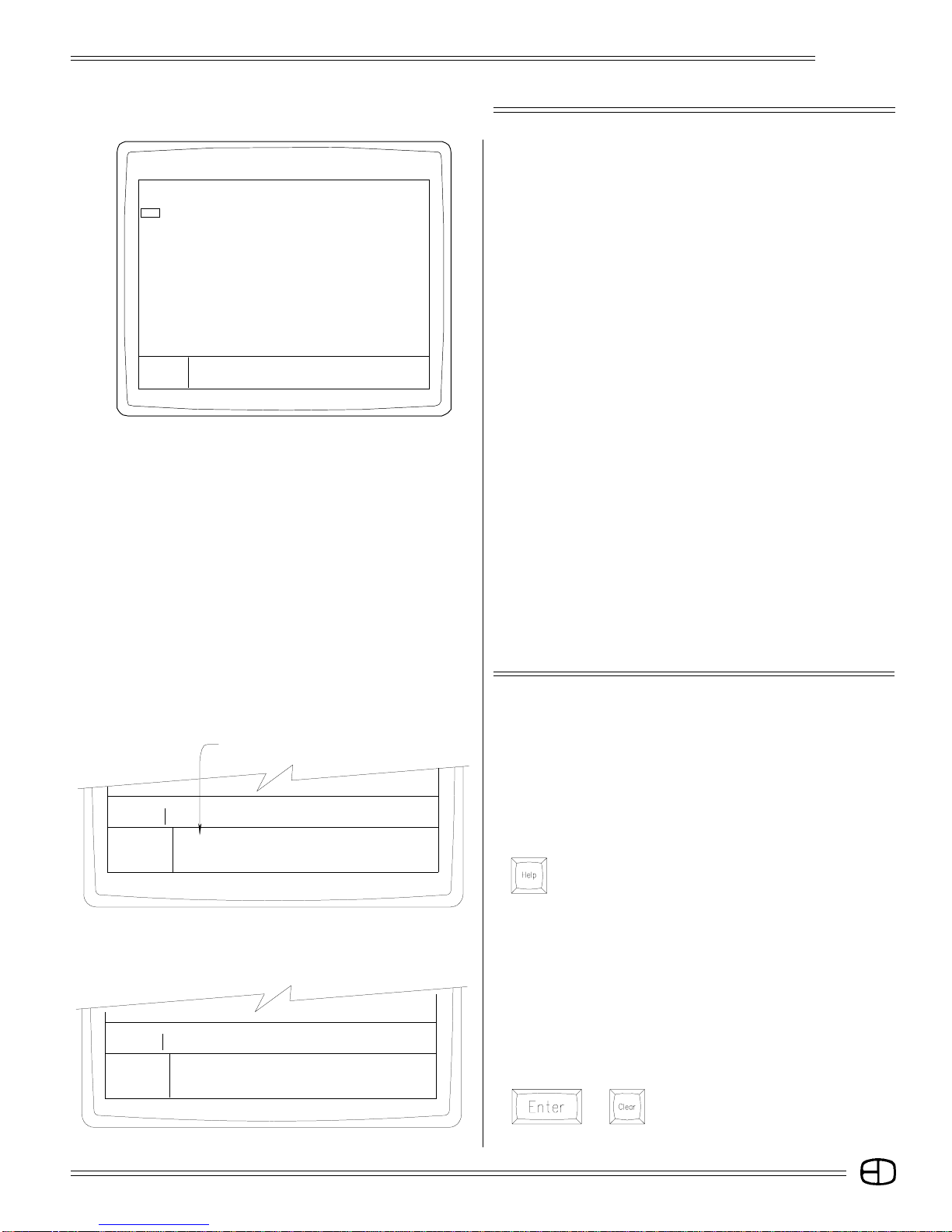
Active Keys are Screen Dependent
Group Name
6 House Lights
HELP: Active Keys: xxxx xxxxxxxx xxxxxxx xxxxxxx xxxxxxx
Press a Key Press ENTER or CLEAR to leave help mode.
HELP: RECORD Will record shown levels to a cue, group or sub.
Press a Key window that is not saved until JUMP or RECORD is pressed.
xxxxxxx xxxxxxxx xxxxxxxx xxxxx xxxxx xxxxxxxx xxxxxx
Group Name
6 House Lights
Example keys...RECORD GROUP 5 ENTER. This will bring up a
USING THE HELP WINDOW
The Help feature is an embedded window that appears whenever
the [HELP] key is pressed. The Help feature offers an on-line prompt
or definition of any key pressed when the Help window is open. The
keys defined are limited to the active screen. The Help feature, along
with the prompt window, offer user support during operation.
TO SELECT HELP:
Press
The Help Window will appear.
TO LEARN MORE ABOUT THE ACTIVE KEY:
Press any LISTED key for an explanation.
A definition of the key function will appear in the Help Window.
More than one key can be selected. Each selection will reveal a
new key definition or example.
Remember that the keys defined are limited to those applicable
to the active screen.
TO SELECT HELP:
Press
or The screen will be restored to the previous
condition.
17

STAGE SCREEN
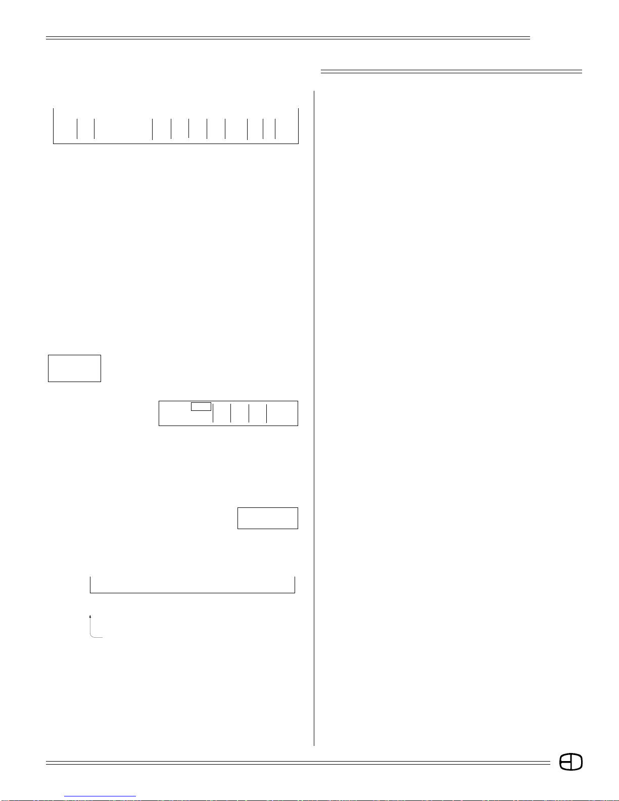
STAGE Omega 2 Grandmaster FL 9:01:00
1 0
2 03 04 05 06 07 08 09101112131415161718192021222324
025 26 27 28 29 30 31 32 33 34 35 36 37 38 39 40 41 42 43 44 45 46 47 48
0
49 50 51 52 53 54 55 56 57 58 59 60 61 62 63 64 65 66 67 68 69 70 71 72
073 74 75 76 77 78 79 80 81 82 83 84 85 86 87 88 89 90 91 92 93 94 95 96
Sub1 S2 S3 S4 S5 S6 S7 S8 S9 S10 S11 S12 S13 S14 S15 S16 S17 S18 S19 S20 S21 S22 S23 S24
197 98 99 00 01 02 03 04 05 06 07 08 09 10 11 12 13 14 15 16 17 18 19 20
Pg
S Cue Name Time Delay Link Ma c EA EB
AP 0 Blackout Cue 0 0 0 0 0 0
Enter: Fdr: 1 2 3 4
Channel Number Cue: text color
Or At %: / / / / *****************
〉
〉
Screen Colors:
Channel Numbers . . . . . . . . . . . . . . . . . . . . . . . . . . . . . . . . . . . . . . . . . . . . . . . . . Green
Selected Channels . . . . . . . . . . . . . . . . . . . . . . . . . . . . . . . . . . . . . . . . . . . . . . . . Yellow
Manually Set Levels . . . . . . . . . . . . . . . . . . . . . . . . . . . . . . . . . . . . . . . . . . . . . . Brown
Cue Levels . . . . . . . . . . . . . . . . . . . . . . . . . . . . . . . . . . . . . . . . . . . . . . . . . . . . . . . . White
Submaster Levels . . . . . . . . . . . . . . . . . . . . . . . . . . . . . . . . . . . . . . . . . . . . . . . . . . Blue
Effects Levels . . . . . . . . . . . . . . . . . . . . . . . . . . . . . . . . . . . . . . . . . . . . . . . . . . . . Purple
Omega 2
STAGE SCREEN PREVIEW
The Control Console supports a SVGA monitor. When powered
up, the console automatically defaults to the Stage Screen as
pictured on the left. The Stage Screen has seven basic groups of
information that alert the operator to the current status of operation.
The seven basic groups include the:
Title Block
Channel Field
Cue Window
Prompt Window
Fader Display
Text Color
Command Line.
The two cursor positions default to the upper left corner of the
monitor. The single-character cursor in the extreme upper corner
corresponds to the remote alphanumeric keyboard.
The double-character cursor position identifies the current field
to be addressed by the console keypads. It can be repositioned
using by the [JUMP] key.
STAGE Omega 2 Grandmaster FL 9:01:00
Title Block
2-character Channel Cursor
1 02 03 04 05 06 07 08 0910111213141516171819202122 2324
025 26 27 28 29 30 31 32 33 34 35 36 37 38 39 40 41 42 43 44 45 46 47 48
049 50 51 52 53 54 55 56 57 58 59 60 61 62 63 64 65 66 67 68 69 70 71 72
073 74 75 76 77 78 79 80 81 82 83 84 85 86 87 88 89 90 91 92 93 94 95 96
Sub1 S2 S3 S4 S5 S6 S 7 S 8 S9 S10 S 11 S12 S13 S14 S 15 S16 S17 S18 S19 S20 S21 S22 S23 S24
197 98 99 00 01 02 03 04 05 06 07 08 09 10 11 12 13 14 15 16 17 18 19 20
Pg
Brown border
TITLE BLOCK:
The Title Block, positioned on the top line of the screen, includes
the following items:
Screen Label: Identifies active screen in green.
Show Title: Custom show title can be positioned here.
(See Setup, System Menu, page 13, #12)
Grand Master: Indicates the level of the system Grand
Master. Levels less than Full display in red.
System Clock: Indicates the time of day.
(See Setup, Time Functions Menu, page 16, #6)
CHANNEL FIELD:
The Channel Field is outlined by a brown border. The numbers
inside the brown line represent the system channels and
submasters. The Channel Field contains the following elements:
Channel Cursor: Two-character reverse video square in upper
left corner.
Active Channels: Represented by green numbers. Levels
entered are displayed below the numbers.
Sub Numbers: Represented by the Sub or S symbol above
the bottom row. Displayed in gray when
inactive or mode color when in use.
Channel Labels: Two rows of alphanumeric text can be
assigned directly above each channel
number. A single -character reverse video
square represents active label position.
Active text color is displayed in the lower
right corner of the monitor. The active color
is selected by the [COLOR UP] or the
[COLOR DN] keys on the remote alphanumeric keyboard.
18
STAGE SCREEN
S Cue Name Time Delay Link Mac EA EB
AP 0 Blackout Cue 0 0 0 0 0 0
Omega 2
CUE WINDOW:
The Cue Window displays the current cue position as well as the
next two sequentially recorded cue actions. The active cue in the
list is always highlighted. Across the Cue Window are the
individual characteristics of the cue. These characteristics can
be addressed each time a cue is recorded.
S: Sets the type of cue action.
Cue: Position for cue number.
Name: Position for cue name.
Time: Divided into two distinct positions:
First position assigns time for fade up.
Second position assigns time for fade down.
Delay: Divided into two distinct positions:
First position is for delay prior to start of fade up.
Second position is for delay prior to start of fade
down.
Link: Allows you to attach a cue to another cue out of
sequence.
Macro: Allows you to execute a macro using a cue action.
EA/EB: The assigned Special Effects number will start with
the cue action.
Enter:
Channel Number
Or At:
〉
〉
Are You Sure?
Command Line
Fdr: 1 2 3 4
Cue:
%: __/__M __/__ __/__ __/__
text color
***************
PROMPT WINDOW:
The Prompt Window offers simple suggestions to alert you to the
next action you can take based on cursor location.
FADER WINDOW:
The Fader Window displays the current cue number loaded to a
fader position. The window also displays the current state of the cue,
percentage played, or stopped position. The Fader Window is
displayed on the Stage, Preview, and Submaster Screens.
Fader: When highlighted, indicates the active fader.
Cue: Indicates the active cue loaded to the fader.
%: Displays percentage of fade time left.
TEXT COLOR:
Text color is controlled from the keyboard with the [COLOR UP]
and [COLOR DN] keys. When the color is changed, the Text
Color statement will reflect the active color.
COMMAND LINE:
The Command Line is located below the brown border on the
lower left side of your monitor. The Command Line position is
represented by " ñ ".
The Command Line mimics any keystrokes pressed from the
keypad controls. The instructions on the Command Line are
executed after you press the [ENTER] key.
Notice that two symbols appear on the screen.
ñ: (Gray) shows Command Line before [ENTER] key
press.
ñ: (Blue) shows active line additions to the Command
Line.
19
STAGE SCREEN
STAGE Omega 2 Grandmaster FL 9:01:00
[Front of House]
01 02 03 04 05 06 07 08 0 910111213141516171819202122 2324
025 26 27 28 29 30 31 32 33 34 35 36 37 38 39 40 41 42 43 44 45 46 47 48
049 50 51 52 53 54 55 56 57 58 59 60 61 62 63 64 65 66 67 68 69 70 71 72
073 74 75 76 77 78 79 80 81 82 83 84 85 86 87 88 89 90 91 92 93 94 95 96
Sub1 S2 S3 S4 S5 S6 S7 S8 S9 S10 S11 S12 S13 S14 S15 S16 S17 S18S19 S20 S21S22 S23 S24
197 98 99 00 01 02 03 04 05 06 07 08 09 10 11 12 13 14 15 16 17 18 19 20
Pg
S Cue Name Time Delay Link Mac EA EB
AP 0 Blackout Cue 0 0 0 0 0 0
Enter: Fdr: 1 2 3 4
Channel Number Cue: text color
Or At %: / / / / *******************
〉
〉
1 02 03 04 05 06 07 08 0910111213141516171819202122 2324
FL 60 60 60
025 26 27 28 29 30 31 32 33 34 35 36 37 38 39 40 41 42 43 44 45 46 47 48
049 50 51 52 53 54 55 56 57 58 59 60 61 62 63 64 65 66 67 68 69 70 71 72
073 74 75 76 77 78 79 80 81 82 83 84 85 86 87 88 89 90 91 92 93 94 95 96
Sub1 S2 S3 S4 S5 S6 S 7 S8 S9 S10 S11 S12 S13 S14 S15 S16 S1 7 S18 S19 S20 S2 1 S22 S 23 S24
197 98 99 00 01 02 03 04 05 06 07 08 09 10 11 12 13 14 15 16 17 18 19 20
Pg
Channel numbers display in green
Selected numbers display in yellow
Manually set levels display in brown
Omega 2
SETTING LEVELS FROM THE KEYPAD
The Stage Screen offers a real time, live output of any channel
addressed. The white two-character cursor moves whenever
channels are selected using the console keypad. This cursor
represents the active position or keypad point of view on the screen.
The cursor defaults to the top left corner or the first addressable
channel position in any screen.
The structure used to address the channels in the Stage Screen
is based on input from the Control Console. The first digits pressed
on the keypad are automatically considered to be channel numbers
unless information exists on the Command Line. To insure proper
channel address, make sure nothing is on the Command Line or
press the [CLEAR] key before input.
Channel selection is transitioned to level information using the
[AT] key. The [AT] key automatically sets the next numeric entry as
level information. The syntax requires an [ENTER] key press in order
to terminate the statement and execute the request.
Omega 2 supports a dual Command Line structure. The
Command Line at the bottom of the screen confirms the keypad
actions as they occur. The current keypad input is highlighted in
blue. The previous keypad input (items addressed prior to the last
[ENTER] key press) is shown as the gray entry on the Command
Line.
Omega 2 also supports a color-coded display. The colors used
on the channel display are coded to help you identify or note any
change of status on the display at any time.
Channel numbers are displayed in green. When a single channel
or list of channels are accessed through the keypad, they are
considered selected.
Selected channels display in yellow, but only after a bridge key is
entered.
When selected channels are assigned levels from the keypad,
the levels display in brown.
Channel levels set from the manual sliders on the Independent
panel are highlighted in blue.
Levels from the manual sliders operate on a last-action basis.
This means that once the slider level matches the keypad entry level,
the color will change from brown to blue and the manual slider is now
in control. The blue level controls the channel. The brown level has
been removed.
The simple illustrations below will familiarize you with setting
levels from the keypad.
Follow the instructions carefully. Dont jump ahead in the exercise
or the illustrations may not match the text.
Bridge keys highlighted:
[AND], [THRU], [AT], [EXCEPT], [RESTORE], [REM DIM].
S Cue Name Time Delay Link Mac EA EB
Enter: Fdr: 1 2 3 4
Channel Number Cue: text color
Or At %: / / / /
〉
〉
10
FROM THE NUMERIC KEYPAD, SELECT CHANNEL 10:
Press
Notice that channel 10 is called out on the
Command Line.
***************
20
STAGE SCREEN
S Cue Name Time Delay Link Mac EA EB
Enter: Fdr: 1 2 3 4
Channel Number Cue: text color
Or At %: / / / /
〉
〉
10 AND 15 AND
S Cue Name Time Delay Link Mac EA EB
Enter: Fdr: 1 2 3 4
Channel Number Cue: text color
Or At %: / / / /
〉
〉
10 AND 15 AND 17 THRU 20
***************
***************
Omega 2
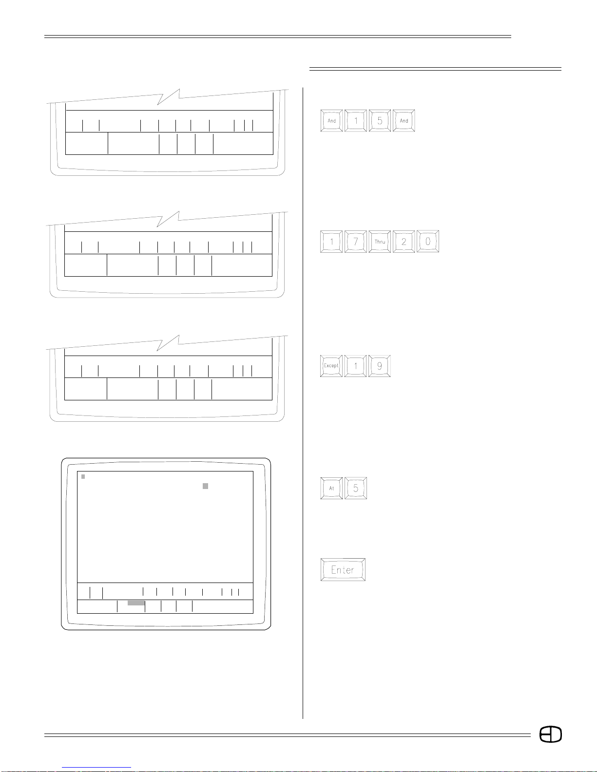
SELECT MORE THAN ONE CHANNEL:
Press
Notice that channel 10 is highlighted
yellow and "10 AND 15" appears on
the Command Line.
The [AND] key forces the previous selection to be highlighted
yellow.
SELECT A LIST OF CONSECUTIVE CHANNELS:
Press
Notice that channel 15 is now
highlighted yellow, but the other
channels are not yellow until a
bridge key like [AND], [THRU], and/or [EXCEPT] are used.
S Cue Name Time Delay Link Mac EA EB
Enter: Fdr: 1 2 3 4
Channel Number Cue: text color
Oa At %: / / / /
〉
〉
10 AND 15 AND 17 THRU 20 EXCEPT 19
STAGE Omega 2 Grandmaster FL 9:01:00
1 02 03 04 05 06 07 08 0910111213141516171819 20 21 22 23 24
025 26 27 28 29 30 31 32 33 34 35 36 37 38 39 40 41 42 43 44 45 46 47 48
049 50 51 52 53 54 55 56 57 58 59 60 61 62 63 64 65 66 67 68 69 70 71 72
073 74 75 76 77 78 79 80 81 82 83 84 85 86 87 88 89 90 91 92 93 94 95 96
Sub1 S2 S3 S4 S5 S6 S7 S8 S9 S10 S11 S12 S13 S14 S15 S16 S17 S18 S19 S20 S21 S22 S23 S24
197 98 99 00 01 02 03 04 05 06 07 08 09 10 11 12 13 14 15 16 17 18 19 20
Pg
S Cue Name Time Delay Link Ma c EA EB
AP 0 Blackout Cue 0 0 0 0 0 0
Enter: Fdr: 1 2 3 4
Channel Number Cue: text color
Or At %: / / / / ***************
〉
〉
10 AND 15 AND 17 THRU 20 EXCEPT 19 AT 50
50 50 50 50 50
***************
REMOVE A CHANNEL FROM THE CONSECUTIVE LIST:
Press
Notice that channels 16, 17, and 18 are
highlighted yellow.
Channel 19 is now restored to green. Selecting [AT] ends the
channel selection process and transitions the command to
setting the actual level.
ASSIGN A LEVEL TO THE HIGHLIGHTED CHANNELS:
Press
Notice that the Command Line entered a double
digit value (50).
(You can press a single digit and [ENTER] for a 10s value, or a
double-digit and [ENTER] for a 10s and 1s value, such as 12. You
must enter a zero in front of a single digit figure; for example, enter
05 to get a level of 5.)
Press
Notice what happened on the screen.
The blue Command Line changed to gray, which indicates the
command action is complete. The channels are no longer
highlighted, but restored to green. Finally, the levels are set in
brown.
Try the channel selections again. This time, make a complete
statement that includes the channel address and the level command.
Watch the Command Line carefully. If you hit the wrong key, use the
backspace arrow in the upper right-hand corner of the selection
keypad to correct the Command Line.
21
STAGE SCREEN
Omega 2
STAGE Omega 2 Grandmaster FL 9:01:00
1 02 3 04 05 06 07 08 091011121314 15161718 192021222324
52 52 FL 52 52 50 50 50 50 50
025 26 27 28 29 30 31 32 33 34 35 36 37 38 39 40 41 42 43 44 45 46 47 48
049 50 51 52 53 54 55 56 57 58 59 60 61 62 63 64 65 66 67 68 69 70 71 72
073 74 75 76 77 78 79 80 81 82 83 84 85 86 87 88 89 90 91 92 93 94 95 96
Sub1 S2 S3 S4 S5 S6 S7 S8 S 9 S10 S11 S12 S13 S14 S15 S16 S17 S18 S19 S20 S21 S22 S23 S24
197 98 99 00 01 02 03 04 05 06 07 08 09 10 11 12 13 14 15 16 17 18 19 20
Pg
S Cue Name Time Delay Link Ma c EA EB
AP 0 Blackout Cue 0 0 0 0 0 0
Enter: Fdr: 1 2 3 4
Channel Number Cue: text color
Or At %: / / / / ***************
〉 1 THRU 5 EXCEPT 3 AT FULL
〉
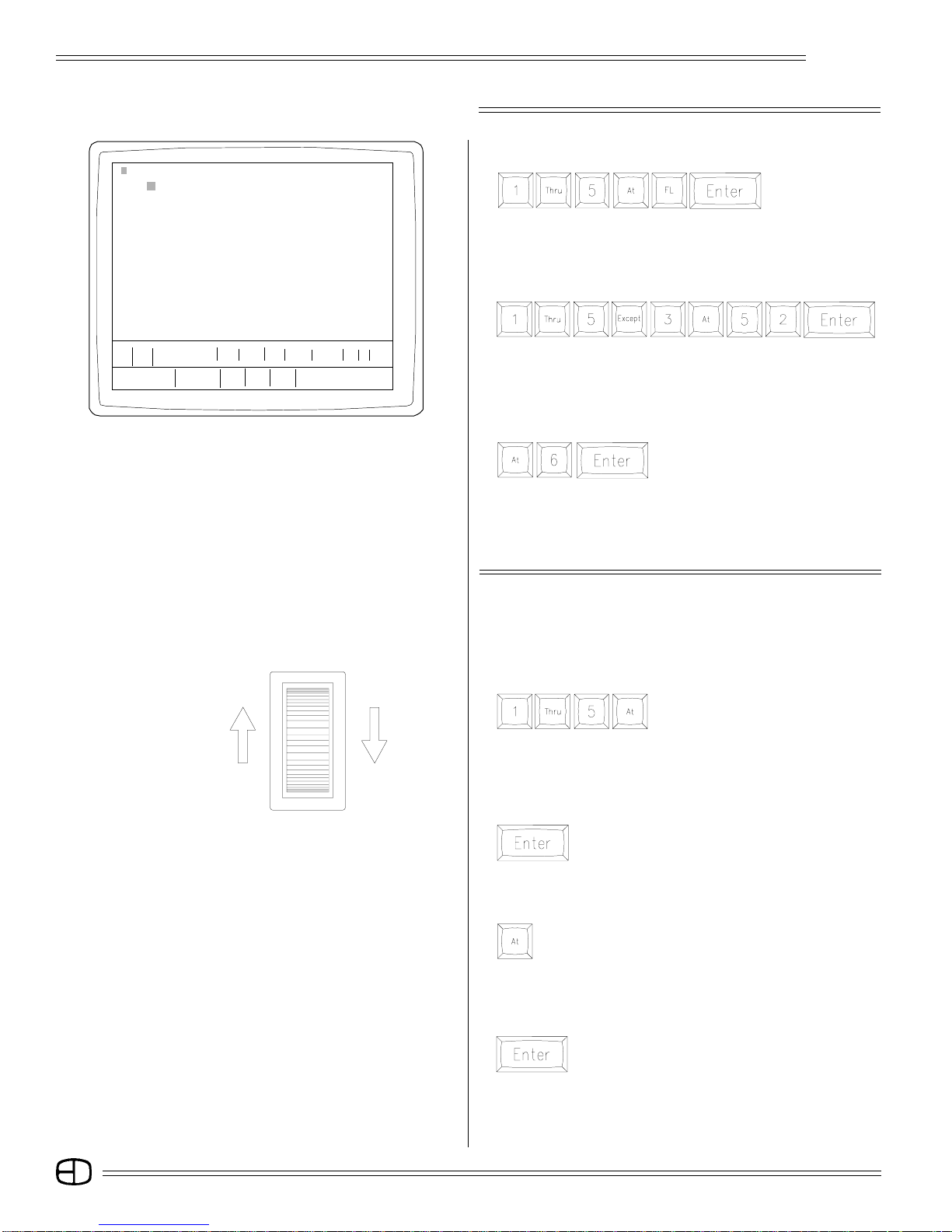
SET CHANNELS 1 THROUGH 5 TO FULL:
Press
Notice that all channels are set at the same levels.
SET CHANNELS 1, 2, 4, & 5 AT 52%: LEAVE CHANNEL 3 AT
FULL:
Press
Notice that channels not included in the string are not disturbed by
the command.
CHANGE THE LEVELS OF 1, 2,4 & 5 TO 60%:
Press
Notice that the last channels can be
re-captured for address again without
entry by simply pressing the [AT] key.
The channels will be highlighted and ready to receive a new level
command. This can only occur when the cursor has not been
moved.
FULL
ZERO
CONTROLLING LEVELS WITH THE WHEEL
Channel numbers with assigned levels can be controlled by the
wheel. To access level wheel control, follow the steps below:
ACCESS WHEEL CONTROL:
Press:
Selected channels are yellow.
Raise or lower the Wheel. Make sure the wheel is set to "Active"
in the Setup Screen, Front Panel Menu, page 14.
TO RELEASE CHANNELS FROM LEVEL WHEEL CONTROL:
Press
Notice that the channel numbers are no longer
highlighted and the wheel is inactive.
TO ACCESS THE SAME CHANNELS & RESET LEVELS:
Press
Previous channels are selected again and controlled by the
level wheel.
TO RELEASE THE CHANNELS WITH THE LEVELS SET FROM
THE LEVEL WHEEL:
Press
Channels are released and levels are set. Channels
are also released when [CLEAR] is pressed.
22
STAGE SCREEN
Omega 2
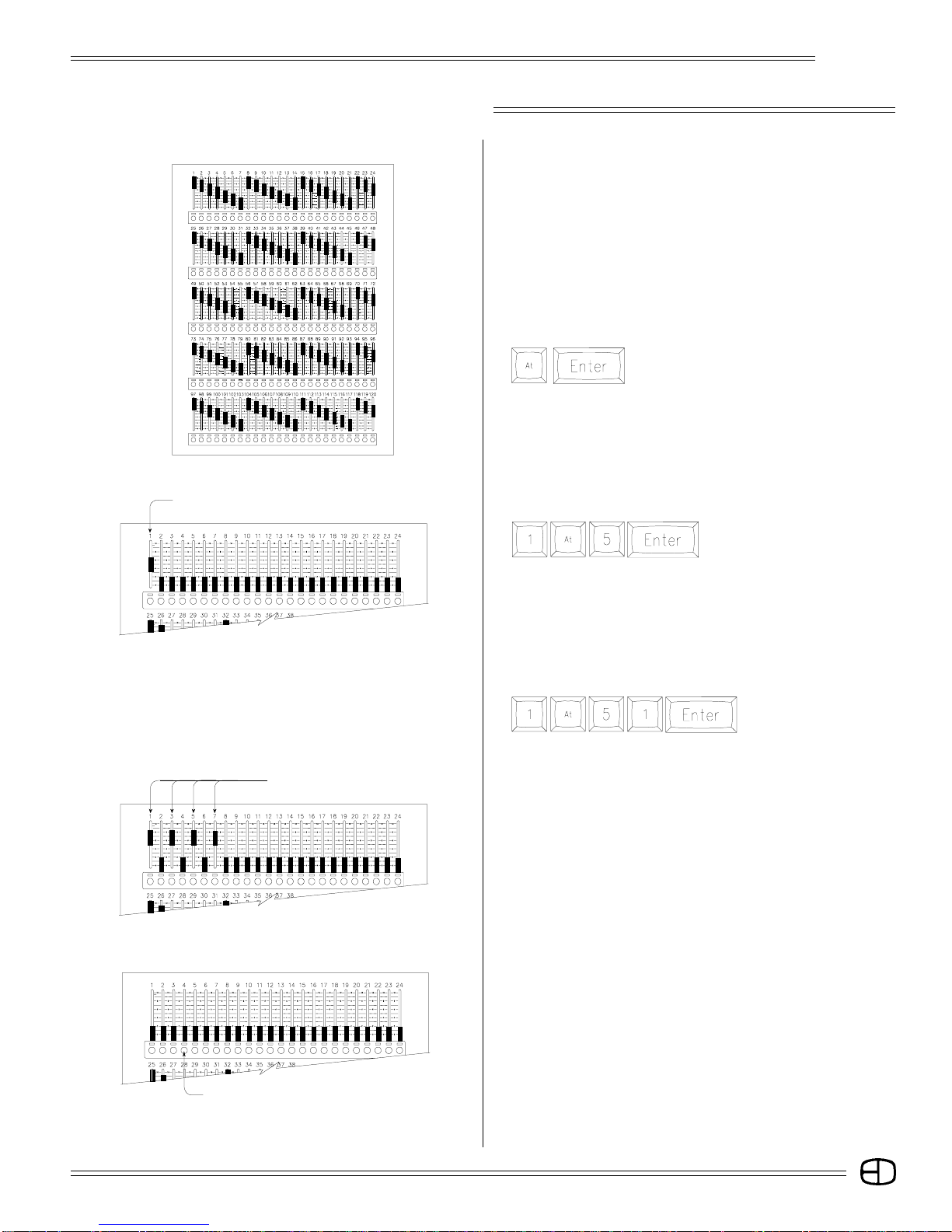
SETTING LEVELS WITH SLIDERS
Another way to introduce levels to the Stage Screen is to Pile On
levels using the manual sliders on the independent panel. This
offers an easy way to set levels on the Stage Screen. Inputs from the
manual sliders are colored blue. These inputs DO NOT highlight the
channel numbers in yellow. They simply Pile On to the Stage Screen.
Manual sliders will take control from a channel based on a lastaction address.
CLEAR THE LAST SET OF CHANNELS AND SET ALL LEVELS
TO NULL VALUES:
Press
Notice that the levels disappeared and the
level field is blank. Blanks, or null values, are
different from zeros.
SET CHANNEL 1 AT 50:
Move manual slider 1 to 50%.
Notice that the level color is blue.
Slider 1 moved to 50
Sliders 1, 3, 5, 7 moved to 75
CALL UP CHANNEL 1 AT 50 ON THE KEYPAD:
Press
Notice that the color stayed blue
even though the Command Line
instruction was correct.
The keypad address level must be greater than the slider level for
the keypad to be in control. This method of operation is called
"highest takes precedence."
CALL UP CHANNEL 1 AT 51 ON THE KEYPAD:
Press
Notice that the level color
changed to brown.
SET CHANNELS 1, 3, 5 AND 7 AT 75%:
Move sliders 1, 3, 5 and 7 to 75%.
The sliders are arranged in rows to match the Stage Screen.
The best way to set levels with the sliders is to watch the screen
and stop the action when the levels meet the desired intensity.
Setting groups of channels to a single level may be quicker using
the keypad. Final adjustments of the levels to balance the Stage
picture may be easier using the sliders.
Bump button
BUMP CHANNEL 1 TO FULL:
Pull all sliders to a zero setting. Press Bump Button under
Channel 1 on the independent slider panel.
The level of channel 1 flashes to Full. The bump level is set using the
Setup Screen, Submaster Menu, page 14, #4.
23
STAGE SCREEN
STAGE Omega 2 Grandmaster FL 9:01:00
1 02 03 04 05 06 07 08 0910111213 14 15 16 17 18 19 20 21 22 23 24
025 26 27 28 29 30 31 32 33 34 35 36 37 38 39 40 41 42 43 44 45 46 47 48
049 50 51 52 53 54 55 56 57 58 59 60 61 62 63 64 65 66 67 68 69 70 71 72
80 75 80 80
Omega 2
SETTING LEVELS IN COMBINATION
USE THE KEYPAD, WHEEL AND SLIDERS TOGETHER:
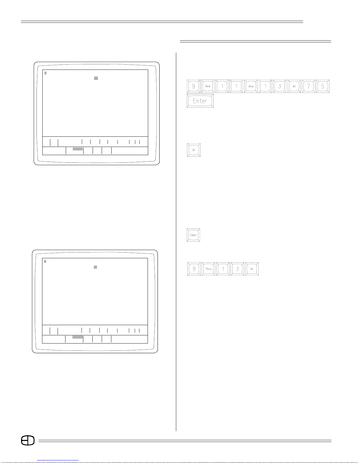
From the keypad, set channels 9, 11, and 13 at 75.
Press
073 74 75 76 77 78 79 80 81 82 83 84 85 86 87 88 89 90 91 92 93 94 95 96
Sub1 S2 S3 S4 S5 S6 S7 S8 S 9 S10 S11 S12 S13 S14 S15 S16 S17 S18 S19 S20 S21 S22 S23 S24
197 98 99 00 01 02 03 04 05 06 07 08 09 10 11 12 13 14 15 16 17 18 19 20
Pg
S Cue Name Time Delay Link Mac EA EB
AP 0 Blackout Cue 0 0 0 0 0 0
Enter: Fdr: 1 2 3 4
Channel Number Cue: text color
Or At %: / / / / ***************
〉 9 AND 11 AND 13 AT 75
〉 9 AND 11 AND 13 AT 75
STAGE Omega 2 Grandmaster FL 9:01:00
1 02 03 04 05 06 07 08 0910111213 14 15 16 17 18 19 20 21 22 23 24
025 26 27 28 29 30 31 32 33 34 35 36 37 38 39 40 41 42 43 44 45 46 47 48
049 50 51 52 53 54 55 56 57 58 59 60 61 62 63 64 65 66 67 68 69 70 71 72
073 74 75 76 77 78 79 80 81 82 83 84 85 86 87 88 89 90 91 92 93 94 95 96
Sub1 S2 S3 S4 S5 S6 S7 S8 S 9 S10 S11 S12 S13 S14 S15 S16 S17 S18 S19 S20 S21 S22 S23 S24
197 98 99 00 01 02 03 04 05 06 07 08 09 10 11 12 13 14 15 16 17 18 19 20
Pg
S Cue Name Time Delay Link Ma c EA EB
AP 0 Blackout Cue 0 0 0 0 0 0
Enter: Fdr: 1 2 3 4
Channel Number Cue: text color
Or At %: / / / / ***************
〉
〉 9 THRU 13 AT
80 75 80 80
All are set brown at 75%.
CAPTURE ALL ON THE WHEEL:
From the keypad, set channels 9, 11, and 13 at 75.
Press
Notice the selected channels are highlighted yellow.
RAISE THE SELECTED LEVELS USING THE WHEEL:
Move the wheel up slowly until the levels under the channels read
80%.
SET 10 AT 75 WITH A SLIDER:
Move channel 10 slider up to 75.
Notice 10 is blue while the others are brown.
RELEASE CHANNELS FROM THE WHEEL:
Press
The channels are no longer highlighted.
CAPTURE 9 THROUGH 13 ON THE WHEEL AGAIN:
Press
All the channels in the group
are highlighted.
SET A NEW LEVEL AT 85%:
Move the wheel up.
The wheel captured all the channels on the Command Line.
The slider channel (10) changed to brown and moved
proportionally with the other channels in the group (highest takes
precedence rule). Channel 12 had no value. The wheel cannot
add value where none exists.
MOVE ALL THE CHANNELS TO FULL:
Move the wheel up to Full.
Notice how the levels all attained a Full value.
SET LEVELS AT 80:
Move the wheel down to 80.
Notice how they all moved off Full at the same time, and they lost
their proportional value.
When the wheel takes all channels in a proportional group to Full,
the channels lose their proportional relationship.
24
STAGE SCREEN
STAGE Omega 2 Grandmaster FL 9:01:00
1 02 03 04 05 06 07 08 0910111213 14 15 16 17 18 19 20 21 22 23 24
025 26 27 28 29 30 31 32 33 34 35 36 37 38 39 40 41 42 43 44 45 46 47 48
049 50 51 52 53 54 55 56 57 58 59 60 61 62 63 64 65 66 67 68 69 70 71 72
073 74 75 76 77 78 79 80 81 82 83 84 85 86 87 88 89 90 91 92 93 94 95 96
Sub1 S2 S3 S4 S5 S6 S7 S8 S 9 S10 S11 S12 S13 S14 S15 S16 S17 S18 S19 S20 S21 S22 S23 S24
197 98 99 00 01 02 03 04 05 06 07 08 09 10 11 12 13 14 15 16 17 18 19 20
Pg
S Cue Name Time Delay Link Mac EA EB
AP 0 Blackout Cue 0 0 0 0 0 0
Enter: Fdr: 1 2 3 4
Channel Number Cue: text color
Or At %: / / / / *****************
〉
〉 9 THRU 13 AT UP
80 80 80 80
Omega 2
There are two ways to regain the proportional level again. Normally,
an operator looks for the quickest, easiest or shortest number of
keystrokes to accomplish this goal.
RELEASE WHEEL CONTROL:
Press
Channels are no longer highlighted.
MATCH CHANNEL 10'S SLIDER TO THE LEVEL ON STAGE:
Move the slider up to 80.
Notice the color change when they match.
RESET CHANNEL 10'S SLIDER TO 75:
Move the slider level to 75.
Sound complicated? The action was simple. Now, let's try the
other way.
First the set-up:
SET 9 THROUGH 13 AT 80:
Press
Move the wheel up so that all levels are at Full. The level colors are
all brown.
PULL THE WHEEL TO 80:
Move the wheel down.
We are now at the same place.
RELEASE SELECTED CHANNELS FROM THE WHEEL:
Press
STAGE Omega 2 Grandmaster FL 9:01:00
1 02 03 04 05 06 07 08 0910111213 14 15 16 17 18 19 20 21 22 23 24
025 26 27 28 29 30 31 32 33 34 35 36 37 38 39 40 41 42 43 44 45 46 47 48
049 50 51 52 53 54 55 56 57 58 59 60 61 62 63 64 65 66 67 68 69 70 71 72
073 74 75 76 77 78 79 80 81 82 83 84 85 86 87 88 89 90 91 92 93 94 95 96
Sub1 S2 S3 S4 S5 S6 S7 S8 S 9 S10 S11 S12 S13 S14 S15 S16 S17 S18 S19 S20 S21 S22 S23 S24
197 98 99 00 01 02 03 04 05 06 07 08 09 10 11 12 13 14 15 16 17 18 19 20
Pg
S Cue Name Time Delay Link Ma c EA EB
AP 0 Blackout Cue 0 0 0 0 0 0
Enter: Fdr: 1 2 3 4
Channel Number Cue: text color
Or At %: / / / / ***************
〉
〉
75
SET 10 AT 75:
Press
Channel 10 is set at 75 with 6 keystrokes.
Normally, the best method to accomplish a task is the one you
remember. Either of the methods above accomplishes the same
goal. It should be clear that there are advantages to having the
sliders for controls as well as the keypad.
TO CLEAR BROWN LEVELS FROM THE CHANNEL DISPLAY:
Press
Notice that the brown channels were removed from the display.
The manual level on channel 10 is still active (blue). Move the
manual slider to the bottom position to clear its level. Move all
sliders to the bottom (zero) position.
25
STAGE SCREEN
S Cue Name Time Delay Link Mac EA EB
Omega 2
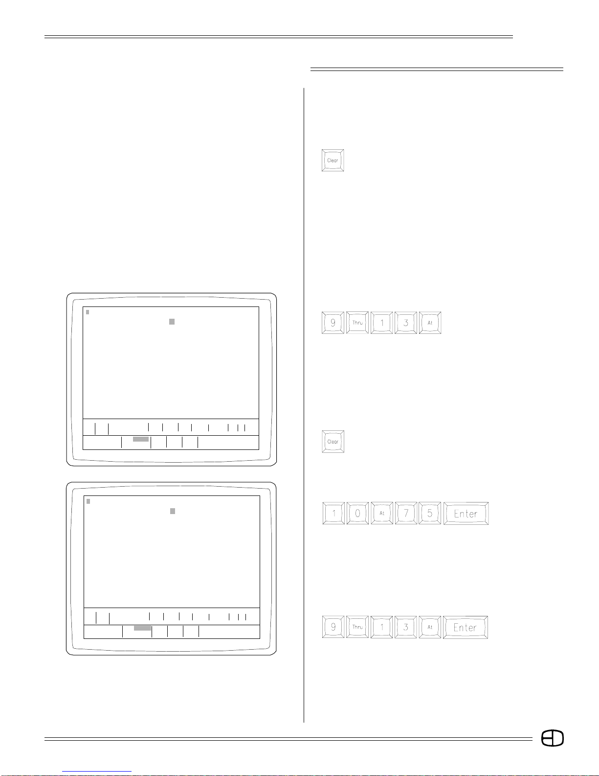
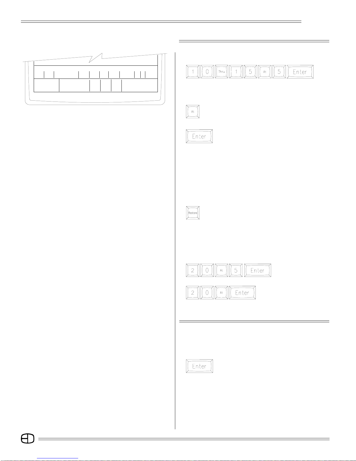
SET 10 THROUGH 15 AT 50:
Press
Enter:
Channel Number Cue: text color
Or At %: / / / /
〉
〉
10 THRU 15 AT 50
Fdr:
12 3 4
**************
10 thru 15 are now at 50.
CLEAR THE LEVELS SET FOR 10 THROUGH 15:
Press
Notice that the [AT] key highlights all the selected channels
in yellow.
Press
Now the [ENTER] key clears the screen.
Selecting [AT] without setting a level forces the channels selected
to a NULL condition.
If you press [AT] [ENTER] by mistake, or the levels have been
changed and need to be recalled at the previous value, use the
[RESTORE] key to recall the last levels set prior to the [AT]
[ENTER] keystrokes.
RESTORE THE LEVELS SET FOR 10 THROUGH 15:
Press
Notice that the levels are restored without the use of the
[ENTER] key.
Restore is an action key that does not require the [ENTER] key to
complete the action. [RESTORE] will only recall one instruction
set prior to the [ENTER] key.
Another way to set a channel's level to null is to follow the
sequence below:
Press
Channel 20 is set with a
level of 50.
Press
Notice that if a channel is
selected without a value, the
[ENTER] key removes the
selected level from the highlighted field.
SELECT & CONTROL ALL CHANNELS AT ONCE
ALL CHANNELS CAN BE SELECTED AND CONTROLLED BY
THE WHEEL IN THE FOLLOWING SEQUENCE:
Press
All the channel numbers are highlighted in yellow.
The Command Line calls out all system channels
ANY CHANNEL WITH A LEVEL ASSIGNED CAN BE ADJUSTED
BY THE LEVEL WHEEL:
Move the level wheel up to any number.
Again, notice that all levels move together.
26
STAGE SCREEN
Omega 2
STAGE Omega 2 Grandmaster FL 9:01:00
1 02 03 04 05 06 07 08 0910111213141516171819202122 2324
025 26 27 28 29 30 31 32 33 34 35 36 37 38 39 40 41 42 43 44 45 46 47 48
049 50 51 52 53 54 55 56 57 58 59 60 61 62 63 64 65 66 67 68 69 70 71 72
073 74 75 76 77 78 79 80 81 82 83 84 85 86 87 88 89 90 91 92 93 94 95 96
Sub1 S2 S3 S4 S5 S6 S7 S8 S9 S10 S11 S12 S13 S14 S15 S16 S17 S18 S19 S20 S21 S22 S23 S24
197 98 99 00 01 02 03 04 05 06 07 08 09 10 11 12 13 14 15 16 17 18 19 20
Pg
S Cue Name Time Delay Link Ma c EA EB
AP 0 Blackout Cue 0 0 0 0 0 0
Enter: Fdr: 1 2 3 4
Channel Number Cue: text color
Or At %: / / / / ***************
〉
〉 1 THRU 120 AT
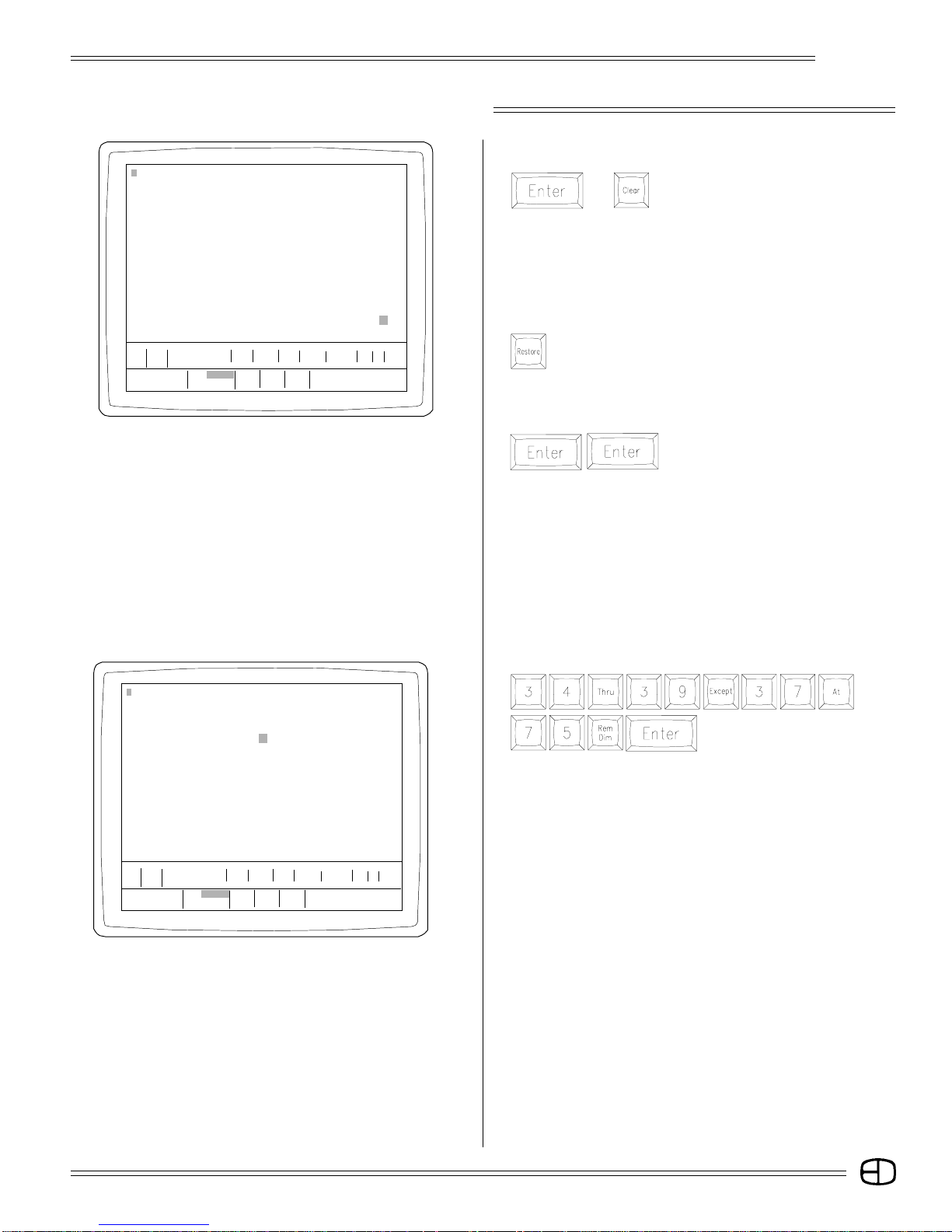
TO RELEASE THE SELECTED CHANNELS AT THE NEW LEVELS:
Press
or
Notice that the channels are no longer
highlighted and new levels are set.
[CLEAR] is the ideal key to use because it clears the Command
Line. The [BACKSPACE] key can accomplish the same goal,
however, it requires more key strokes.
TO RETURN TO THE PREVIOUS VALUES PRIOR TO THE
LEVEL WHEEL ADJUSTMENT:
Press
Notice that the levels changed to the previous setting.
Now it is possible to eliminate all levels assigned to the channels
on the display.
Press
This response is similar to the
keystrokes [AT] [ENTER].
The primary difference is [AT] [ENTER] eliminates the levels
assigned to the highlighted channels while [ENTER] [ENTER]
selects all the channels with the first [ENTER] and eliminates all
the levels assigned to all channels with the second [ENTER].
If you accidently press [ENTER] [ENTER], you can return the
channels to the previous levels by pressing the [RESTORE] key.
STAGE Omega 2 Grandmaster FL 9:01:00
1 02 03 04 05 06 07 08 09 10 11 12 13 14 15 16 17 18 19 20 21 22 23 24
025 26 27 28 29 30 31 32 33 34 35 36 37 38 39 40 41 42 43 44 45 46 47 48
049 50 51 52 53 54 55 56 57 58 59 60 61 62 63 64 65 66 67 68 69 70 71 72
073 74 75 76 77 78 79 80 81 82 83 84 85 86 87 88 89 90 91 92 93 94 95 96
Sub1 S2 S3 S4 S5 S6 S7 S8 S9 S10 S11 S12 S13 S14 S15 S16 S17 S18 S19 S20 S21 S22 S23 S24
197 98 99 00 01 02 03 04 05 06 07 08 09 10 11 12 13 14 15 16 17 18 19 20
Pg
S Cue Name Time Delay Link Ma c EA EB
AP 0 Blackout Cue 0 0 0 0 0 0
Enter: Fdr: 1 2 3 4
Channel Number Cue: text color
Or At %: / / / / ***************
〉
〉 34 THRU 39 EXCEPT 37 AT 75 REMDIM
00 00 00 00 00 00 00 00
75 75 75 75 75
Another action key that is useful in setting and modifying levels is
the [REM DIM] key. [REM DIM] forces all remaining channels
(except those specified on the Command Line) to zero.
Press
Notice that all other channels were forced to a null output.
You can always press [RESTORE] immediately to recall the
previous channels with their assigned values.
SUMMARY:
Setting levels is a basic function of the numeric and selection
keypads. The syntax used to assign levels to channels is very
straightforward. The first digits are always channel numbers.
The [AT] key is used to bridge between channels and levels. All
Command Line instructions end with the [ENTER] key.
Sometimes it may be helpful to repeat the syntax out loud as
you perform the keystrokes. Keep your eye on the Command Line
at the base of the display as you make the keystrokes. Take your
time with the keystrokes to insure the correct key strokes until you
feel comfortable with the structure.
This procedure for setting levels is the same in the Submaster,
Preview and Track Screens.
27
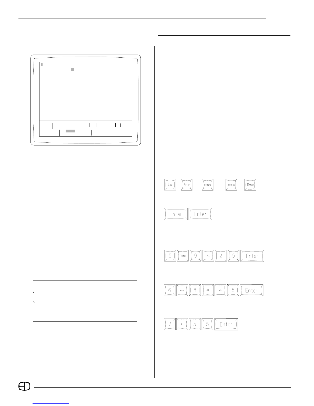
STAGE SCREEN
STAGE Omega 2 Grandmaster FL 9:01:00
1 02 03 04 05 06 07 08 9 10 11 12 13 14 15 16 17 18 19 20 21 22 23 24
025 26 27 28 29 30 31 32 33 34 35 36 37 38 39 40 41 42 43 44 45 46 47 48
049 50 51 52 53 54 55 56 57 58 59 60 61 62 63 64 65 66 67 68 69 70 71 72
073 74 75 76 77 78 79 80 81 82 83 84 85 86 87 88 89 90 91 92 93 94 95 96
Sub1 S2 S3 S4 S5 S6 S7 S8 S9 S10 S11 S12 S13 S14 S15 S16 S17 S18 S19 S20 S21 S22 S23 S24
197 98 99 00 01 02 03 04 05 06 07 08 09 10 11 12 13 14 15 16 17 18 19 20
Pg
Enter: Fdr: 1 2 3 4
Channel Number Cue: text color
Or At %: / / / / ***************
〉
〉 5 THRU 9 AT 25
25 25 25 25 250
S Cue Name Time Delay Link Ma c EA EB
AP 0 Blackout Cue 0 0 0 0 0 0
Omega 2
RECORDING CUE LEVELS
Because the Stage Screen is a live output display, any channels
addressed on the Stage Screen automatically force the dimmer
assigned to the channel to the assigned level. After channel levels
have been set using the keypad, they are displayed in brown; slider
levels are displayed in blue. The levels are ready to be recorded and
assigned a position in the system memory.
From the Stage Screen, channels with levels can be assigned to
Cue actions or to Submasters without losing the levels established
on the display.
Follow the steps outlined below to record levels to Cue and
Submaster locations.
NOTE THAT THE INSTRUCTIONS BELOW ASSUME THAT YOU
ARE NOT RECORDING WITH FAST MODE AS THE DEFAULT
SETTING.
The Omega 2 is shipped with Fast Mode as the default setting.
To change out of Fast Mode, go to the Setup Screen, System Menu,
page 13, #5, recording in fast mode, and toggle to "NO".
When you are familiar with recording you can switch back to Fast
Mode. Instructions and routines for setting Cue and Submaster
attributes and times while in Fast Mode appear in later chapters.
Keys highlighted:
[CUE], [JUMP], [RECORD], [SELECT], [TIME].
〉
6 AND 8 AT 45
〉
Command Line
〉 6 AND 8 AT 45
〉 7 AT 55
CLEAR ALL LEVELS FROM THE STAGE SCREEN:
Press
Notice that all channels were forced
to a null output.
You can always press [RESTORE] to recall the channels to their
previous values.
SET CHANNEL 5 THROUGH 9 AT 25:
Press
Notice that 5, 6, 7, 8, and 9 all share the level of 25.
SET CHANNELS 6 AND 8 AT 45:
Press
Notice that 6 and 8 are now at 45.
SET CHANNEL 7 AT 55:
Press
Notice that 7 is now at 55.
28
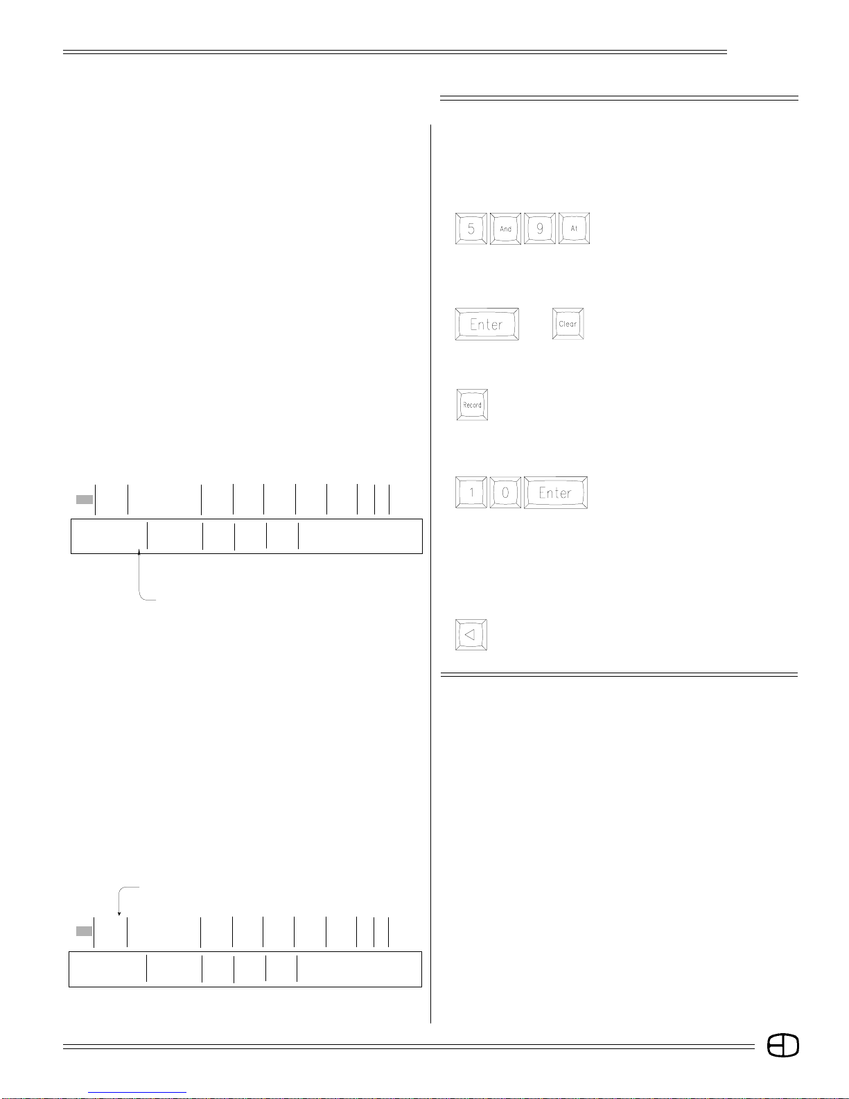
STAGE SCREEN
S Cue Name Time Delay Link Mac EA EB
P 10 10 10 10 10
Omega 2
You can adjust any channel or group of channels or all the
channels proportionally by following the steps below.
USING THE WHEEL TO ADJUST ANY CHANNEL OR GROUP
OF CHANNELS:
Press
Notice that the channels are selected.
You can use the wheel to roll the levels up or down proportionately.
TO RELEASE THE CHANNELS FROM THE WHEEL:
Press
or
Pressing [ENTER] is the best habit
because it suggests acceptance.
TO RECORD THE CHANNEL LEVELS:
Press
The Command Line reflects Record and assumes Cue.
(Make sure you turn the key in the upper right corner to "RECORD
ACCESS.")
Press
The brown levels have now changed
to white.
Enter: Fdr: 1 2 3 4
Select Key Cue: 1 text color
〉 RECORD CUE 10
〉 ORD CUE 10
S Cue Name Time Delay Link Mac EA EB
P 1 Front of House 0 0 0 0 0 0 0 0
T 1 10 10 10 10
Enter: Fdr: 1 2 3 4
Select Key Cue: 1 text color
〉
〉 RECORD CUE 10
%: – – / – – S ***************
Prompt Window
Cue Window
%: – – / – – S ***************
This confirms that the levels are now recorded. The new cue 10
now appears highlighted in the Cue Window.
Note that if you want to access the Cue Window while in Fast Mode,
you would press [JUMP].
MOVE CURSOR TO THE LEFT:
Press
The Prompt Window suggests the Select Key.
CUE ATTRIBUTES
Each cue can support an attribute that defines how the cue will
respond in playback conditions. The attribute is displayed under the
Select column in the first position in the Cue Window.
The console can be set to default to a specific attribute each time
the Record process is completed. The default setting is controlled
in the Setup Screen, Cues Menu, page 13, #2, "All cues have default
preset," Yes or No.
The operator can override the default by positioning the cursor in
'S' (Select) column and pressing the Select key to review the
capacities.
TRACKING:
The console defaults as a tracking cue with a 'T' symbol.
TRACKING means that in a cue, any channels without levels set in
the cue can have levels which track into the cue from previous cues.
29
 Loading...