

Page 1
EnAct
EnAct
Revision 7 September 1998
© 1998, Electronics Diversified, Inc.
User Manual
070-0620
1
Page 2

INTRODUCTION
Sometimes the best results occur when you get a look at the
subject matter from an entirely new direction. This fresh start idea
should start at basic requirements and how to relate information in
a modern age. Many would agree that good lighting controls
should be designed to adapt to an overall performance environment,
not just playback in one. Lighting controls need to adapt to a
changing environment. This is the challenge of the 90s.
The EnAct family of control is designed to offer advanced
features with a new presentation format for a fresh start approach
to control. Control details are now presented in a high definition
SVGA video format. A single video screen can present up to 200
control channels in an easy to read format.
In addition, the screen also provides a detailed active cue window
to inform the operator of the next and last actions. Couple this with
active color coding for channel fields, and an alphanumeric label
capacity for cues, groups, submasters, and effects, and now you
have a dynamic video display that presents concise information in
a clear, readable form to support operator controls.
The EnAct family of control targets flexibility in how the console
operates by user-selectable conditions. The Set-Up Menu offers
the user real choices on how the console will respond. These
conditions allow features like Auto Record, Editing on Track and
Cue Screens, Advancing Submasters, Preset or Track Mode
operations, and Remote Record features. These features can also
be controlled by Macros. The user can switch these features by
Macro or Set-Up Screen, based on preference.
EnAct Consoles offer significant additions in the submaster
playback area of control. With up to eight pages of 24 playbacks,
the EnAct allows the operator to set unique sequences of actions
on the playbacks and operate them in a timed or manual mode.
Timed playbacks can be labeled as advancing so that the
completion of one automatically starts the next. Color-coded
Bump Controls also start and stop actions. The EnAct comes with
a Playback Display, designed to identify and coordinate these
features. Additional features include SMPTE & MIDI control interfaces.
EnAct Consoles offer enhanced performance on a RISC-based
central processing unit. The EnAct is based on work station
technology rather than PC-based controls. This difference is
apparent when large tasks are addressed by the console.
We believe that the EnAct Control family offers real progress in
user controls designed to adapt the changing role of lighting in the
90s.
EnAct
HOW TO USE THIS MANUAL
To assist you through these steps, this Manual offers:
BOLD TITLES: In the upper left and right corner to tell
the reader which section he is using.
KEY LINES: Subheads which describe indexed
categories.
SCREENS: Describe details for easy identification.
KEY STROKES: Actual key presses required to
complete the instruction.
COMMENTS:
EXAMPLES: Common instructions used in normal
SUPPORT: 24-hour Service/Support network.
This User Manual is supplied with your system. Copies of this
guide may be obtained from Electronics Diversified, Inc. for a
nominal charge. It is recommended that you copy those portions
of this manual applicable to your present use in the installation,
maintenance or repair and preserve the original in a safe place.
© 1998, by Electronics Diversified, Inc. All rights reserved.
No part of this manual may be reproduced by any means,
graphic, electronic, or mechanical, including photocopying,
recording, taping, or information storage and retrieval systems,
without the express written permission of Electronics Diversified,
Inc., except in connection with installation, operation, repair and
maintenance of Electronics Diversified, Inc. systems.
Comments about operation in italics.
operation.
2
Page 3

TABLE OF CONTENTS
OVERVIEW
Front Panel . . . . . . . . . . . . . . . . . . . . . . . . . . . . . . . . . . . . . 4
Keypad Layout . . . . . . . . . . . . . . . . . . . . . . . . . . . . . . . . . . 4
Screen Keys . . . . . . . . . . . . . . . . . . . . . . . . . . . . . . . . . . . . 5
Action Keys . . . . . . . . . . . . . . . . . . . . . . . . . . . . . . . . . . . . . 6
Command Keys . . . . . . . . . . . . . . . . . . . . . . . . . . . . . . . . . . 7
Number Keys . . . . . . . . . . . . . . . . . . . . . . . . . . . . . . . . . . . . 8
Selection Keys . . . . . . . . . . . . . . . . . . . . . . . . . . . . . . . . . . . 8
Fader Keys . . . . . . . . . . . . . . . . . . . . . . . . . . . . . . . . . . . . . 9
Macro Keys . . . . . . . . . . . . . . . . . . . . . . . . . . . . . . . . . . . . . 9
Rear Panel . . . . . . . . . . . . . . . . . . . . . . . . . . . . . . . . . . . . . . 10
Side Panel . . . . . . . . . . . . . . . . . . . . . . . . . . . . . . . . . . . . . . 11
Format a Disk . . . . . . . . . . . . . . . . . . . . . . . . . . . . . . . . . . . 11
SYSTEM SETUP
Start Up . . . . . . . . . . . . . . . . . . . . . . . . . . . . . . . . . . . . . . . . 12
Display Screen . . . . . . . . . . . . . . . . . . . . . . . . . . . . . . . . . . 13
STAGE SCREEN
Setting Levels . . . . . . . . . . . . . . . . . . . . . . . . . . . . . . . . . . . 17
Merge, Insert . . . . . . . . . . . . . . . . . . . . . . . . . . . . . . . . . . . 20
Recording Cues . . . . . . . . . . . . . . . . . . . . . . . . . . . . . . . . 21
Modifying Cues . . . . . . . . . . . . . . . . . . . . . . . . . . . . . . . . . 23
Recording Groups . . . . . . . . . . . . . . . . . . . . . . . . . . . . . . 23
Recording Submasters . . . . . . . . . . . . . . . . . . . . . . . . . . . 24
Load & Run Cues . . . . . . . . . . . . . . . . . . . . . . . . . . . . . . . 25
Interrupt Cues . . . . . . . . . . . . . . . . . . . . . . . . . . . . . . . . . . 25
Tracking . . . . . . . . . . . . . . . . . . . . . . . . . . . . . . . . . . . . . . . 26
Cue Window . . . . . . . . . . . . . . . . . . . . . . . . . . . . . . . . . . . 26
PREVIEW SCREEN
Setting Levels . . . . . . . . . . . . . . . . . . . . . . . . . . . . . . . . . . 27
Change Cue Window Information . . . . . . . . . . . . . . . . . . . 27
Copy Cue Levels . . . . . . . . . . . . . . . . . . . . . . . . . . . . . . . 27
SUBMASTER SCREEN
Setting Levels . . . . . . . . . . . . . . . . . . . . . . . . . . . . . . . . . . 28
Change Sub Window Information . . . . . . . . . . . . . . . . . . . 28
Copy Submaster Levels . . . . . . . . . . . . . . . . . . . . . . . . . . 28
GROUP SCREEN
Setting Levels . . . . . . . . . . . . . . . . . . . . . . . . . . . . . . . . . . 29
Change Group Window Information . . . . . . . . . . . . . . . . . 29
Copy Group Levels . . . . . . . . . . . . . . . . . . . . . . . . . . . . . . 29
PLAYBACK SCREEN
Running Playbacks . . . . . . . . . . . . . . . . . . . . . . . . . . . . . . 30
Running Playbacks Manually . . . . . . . . . . . . . . . . . . . . . . . 31
TRACK SCREEN
Setting Levels . . . . . . . . . . . . . . . . . . . . . . . . . . . . . . . . . . 32
CUE LIST SCREEN
Editing the Cue List Screen . . . . . . . . . . . . . . . . . . . . . . . . 33
PATCH SCREEN
Patch by Dimmer . . . . . . . . . . . . . . . . . . . . . . . . . . . . . . . . 34
Parked Dimmers . . . . . . . . . . . . . . . . . . . . . . . . . . . . . . . . . 34
EnAct
Position Controls . . . . . . . . . . . . . . . . . . . . . . . . . . . . . . . . . 34
Unpatch . . . . . . . . . . . . . . . . . . . . . . . . . . . . . . . . . . . . . . . 35
Unity Patch . . . . . . . . . . . . . . . . . . . . . . . . . . . . . . . . . . . . 35
Patch by Channel . . . . . . . . . . . . . . . . . . . . . . . . . . . . . . . 35
Position Controls . . . . . . . . . . . . . . . . . . . . . . . . . . . . . . . . 35
EFFECT SCREEN
Activating Steps by Groups. . . . . . . . . . . . . . . . . . . . . . . . . 36
EFFECT TRACK SCREEN
Setting Levels . . . . . . . . . . . . . . . . . . . . . . . . . . . . . . . . . . 37
Example Effect . . . . . . . . . . . . . . . . . . . . . . . . . . . . . . . . . 37
SETUP SCREENS
Main Menu . . . . . . . . . . . . . . . . . . . . . . . . . . . . . . . . . . . . . 38
System Menu . . . . . . . . . . . . . . . . . . . . . . . . . . . . . . . . . . . 39
Cues Menu . . . . . . . . . . . . . . . . . . . . . . . . . . . . . . . . . . . . 39
Submaster Menu . . . . . . . . . . . . . . . . . . . . . . . . . . . . . . . . 40
Patch Menu . . . . . . . . . . . . . . . . . . . . . . . . . . . . . . . . . . . . 40
Front Panel Menu . . . . . . . . . . . . . . . . . . . . . . . . . . . . . . . 40
Save to Disk Menu . . . . . . . . . . . . . . . . . . . . . . . . . . . . . . 41
Load from Disk Menu . . . . . . . . . . . . . . . . . . . . . . . . . . . . 41
Print Functions Menu . . . . . . . . . . . . . . . . . . . . . . . . . . . . . 41
Clear Menu . . . . . . . . . . . . . . . . . . . . . . . . . . . . . . . . . . . . 42
Time Functions Menu . . . . . . . . . . . . . . . . . . . . . . . . . . . . 42
Peripherals/Utilities Menu. . . . . . . . . . . . . . . . . . . . . . . . . . 43
MISCELLANEOUS SCREENS
Help . . . . . . . . . . . . . . . . . . . . . . . . . . . . . . . . . . . . . . . . . . 44
Macro . . . . . . . . . . . . . . . . . . . . . . . . . . . . . . . . . . . . . . . . 44
Profile . . . . . . . . . . . . . . . . . . . . . . . . . . . . . . . . . . . . . . . . 45
Source . . . . . . . . . . . . . . . . . . . . . . . . . . . . . . . . . . . . . . . . 45
ACCESSORIES
Remote Record . . . . . . . . . . . . . . . . . . . . . . . . . . . . . . . . . 46
Remote Video . . . . . . . . . . . . . . . . . . . . . . . . . . . . . . . . . . 46
Hook-up . . . . . . . . . . . . . . . . . . . . . . . . . . . . . . . . . . . . . . 47
Keyboard . . . . . . . . . . . . . . . . . . . . . . . . . . . . . . . . . . . . . . 47
Printers . . . . . . . . . . . . . . . . . . . . . . . . . . . . . . . . . . . . . . . 47
Hand-held Remote . . . . . . . . . . . . . . . . . . . . . . . . . . . . . . 48
Designer's Remote . . . . . . . . . . . . . . . . . . . . . . . . . . . . . . 48
MIDI . . . . . . . . . . . . . . . . . . . . . . . . . . . . . . . . . . . . . . . . . . 49
SMPTE Screen (Timed Actions) . . . . . . . . . . . . . . . . . . . . 49
Common Questions . . . . . . . . . . . . . . . . . . . . . . . . . . . . . . 50
ADDENDUM
EnAct Chassis . . . . . . . . . . . . . . . . . . . . . . . . . . . . . . . . . . 52
EnAct Front Panel . . . . . . . . . . . . . . . . . . . . . . . . . . . . . . . 53
SERVICE
Service/Support . . . . . . . . . . . . . . . . . . . . . . . . . . . . . . . . . 54
Registration . . . . . . . . . . . . . . . . . . . . . . . . . . . . . . . . . . . . 55
3
Page 4
OVERVIEW
EnAct
3
1
2
4
5 67
89
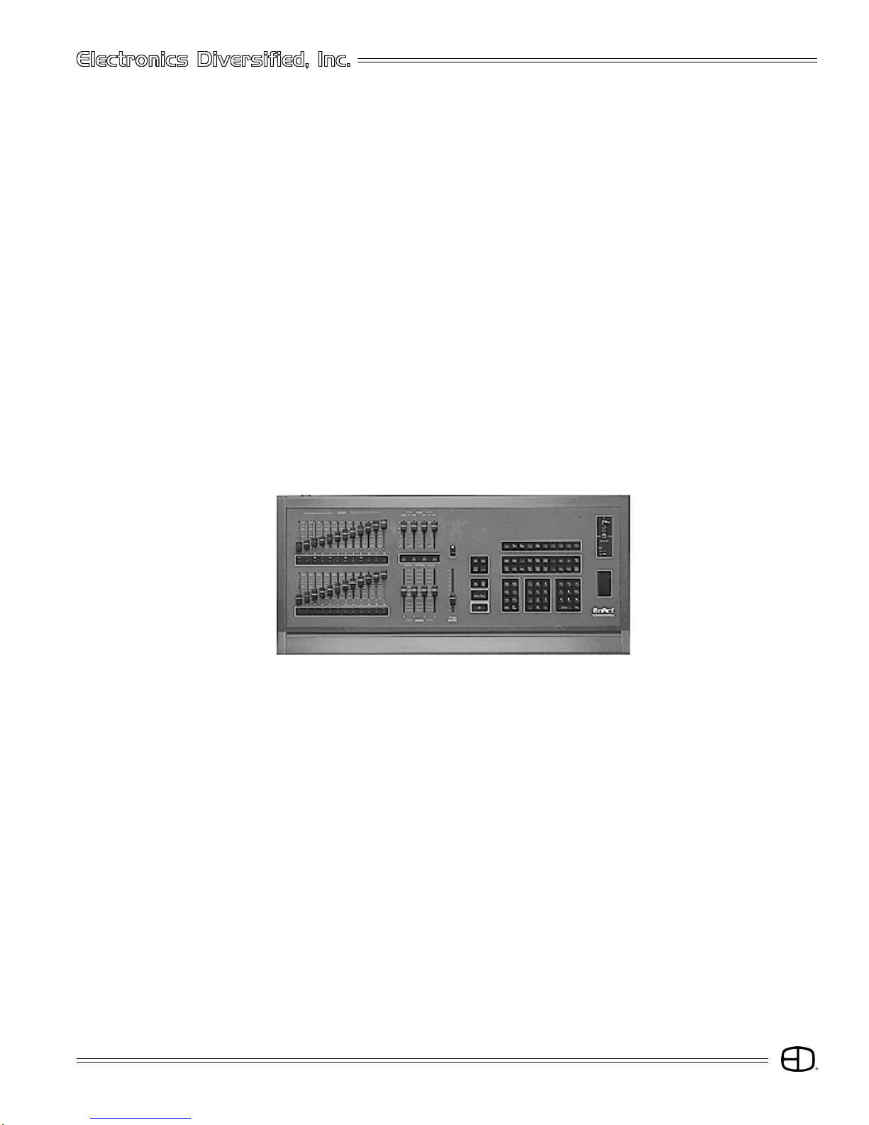
EnAct
The EnAct is a microprocessor-based control system with
all operational instruction sets and controls routines embedded
in read-only memory. The Control Console front panel allows
access to these instructions and routines through key
selections. All key selections are echoed on the system
Command Line located at the bottom left of your monitor.
1. PLAYBACK HANDLES:
Manual control of Submaster playbacks.
2. PLAYBACK BUMP BUTTONS:
Starts timed Submaster playbacks and bumps manuals to a Full
level.
3. EFFECTS CONTROLS:
Time and Level control for the running effects.
4. FADER TAKEOVER BUTTONS:
Captures active fades to a handle and unloads uncompleted
fades from the Faders.
5. MANUAL FADER CONTROLS:
Adjusts fade level from the point captured to Full.
6. COMMAND KEYPAD:
Moves through screens, enters values, and starts functions.
7. ENCODER WHEEL:
Adjusts selected channel levels, and speeds up / slows down
fades.
8. KEY SWITCHES:
Key access to power, record and backup functions.
9. DISK DRIVE:
Off-line storage of recorded show information.
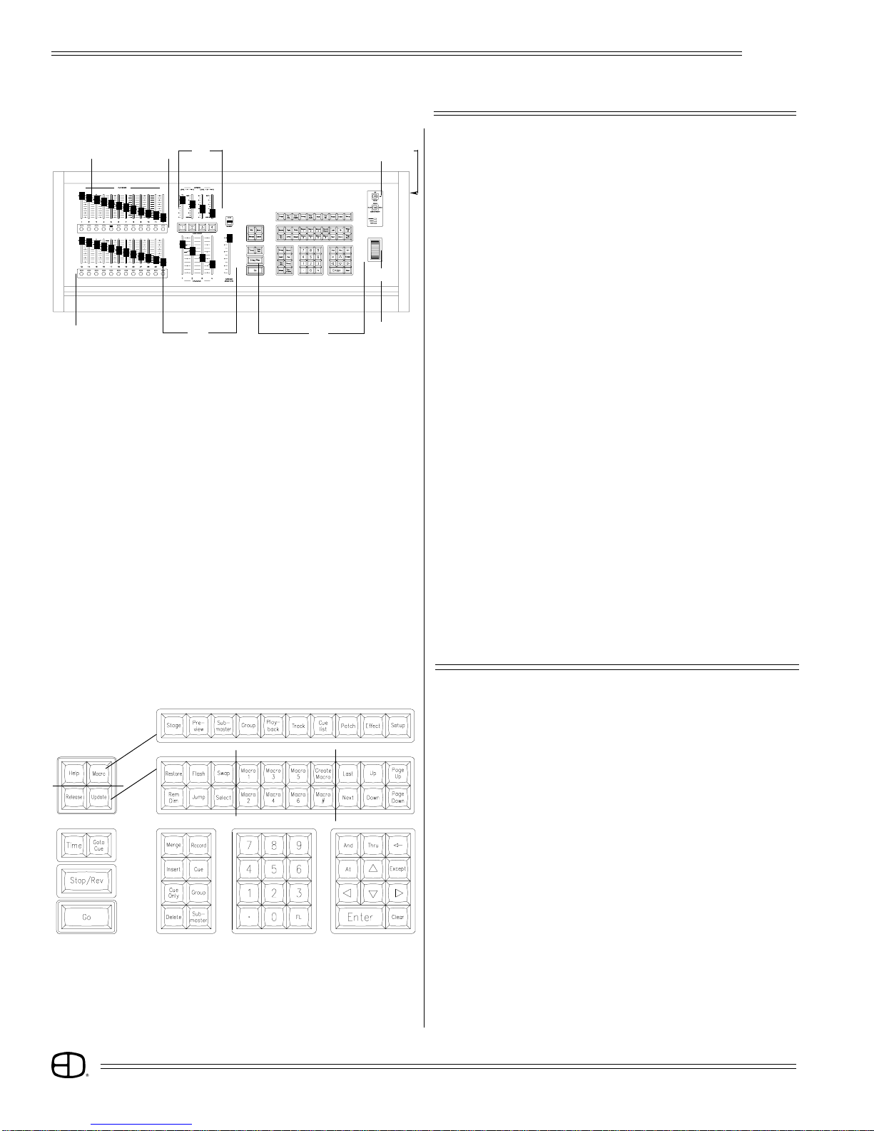
FRONT PANEL
Fader Keys
Screen Keys
Action Keys
Command Keys
Macro Keys
Number Keys
Action Keys
Selection Keys
KEYPAD LAYOUT
The primary access to the control system is through the
keypad controls on the front panel of the console. The keypads
are grouped together under common control headings for
ease of operation. There are seven groups: Screen Keys;
Action Keys; Command Keys; Number Keys; Selection Keys;
Fader Keys and Macro Keys.
The general titles for the grouping of keys indicate their
functions.
4
Page 5

OVERVIEW
EnAct
SCREEN KEYS
STAGE:
This screen shows channels with levels from the various sources.
Also shown is information of the cue on stage and the two
following. Cues, groups and subs can be recorded or rerecorded
and cue times can be changed on this screen. A second press
will show the Source screen, which shows the source of the
channel levels.
PREVIEW:
This screen shows the contents of cues. A cue's levels and
attributes can be edited blind in this screen. New cues can also
be recorded. A second press will show a list of cues with
numbers and names.
SUBMASTER:
This screen shows the contents of submasters. A submaster's
levels and times can be edited blind in this screen. New
submasters can also be recorded. A second press will show a
list of submasters with numbers and names.
GROUP:
This screen shows the contents of groups. A group's levels can
be edited blind in this screen. New groups can also be recorded.
A second press will show a list of groups with numbers and
names.
PLAYBACK:
This screen shows a listing of submasters and the current page
that is active. Times can be changed and handles can be forced
to new pages. The current level of the handle is also shown.
TRACK:
This screen shows the cues in a spreadsheet format. Cue levels
can be edited blind in this screen.
CUE LIST:
This screen shows the list of the cue times and attributes, which
can be edited.
A second press displays the Timed Actions screen. This screen
shows actions that can be started by SMPTE, a timer, or by the
clock.
PATCH:
This screen shows a patch by dimmers. Channels can be
assigned to dimmers as well as proportional levels and profiles.
Also, dimmers can be parked or assigned to submaster handles.
A second press will bring up a Patch by Channel screen.
EFFECT:
This screen will show Effect's steps and times. Group steps can
be added, inserted and deleted. A second press will bring up
the Effect Track screen. In this screen, the step levels are shown
in a spreadsheet format. Effects can be created and edited
simply on this screen.
SETUP:
This screen shows the user-definable parameters. These can
be set to any desired configuration. A second press will bring up
the Profile screen. Preheats and other custom profiles can be
edited.
MACRO:
This screen shows the keyhits of the Macro number displayed.
Macros can also be created and edited.
HELP:
Accesses Help window. Active keys and instructions for each
key are displayed.
5
Page 6

OVERVIEW
EnAct
ACTION KEYS
Action keys are designed to allow direct input to the
screen. Each action may be accompanied by key inputs from
the numeric or selection keypad.
RESTORE:
Returns channels to conditions previous to last entered selection.
REM DIM:
Forces all other levels to '0'. Requires ENTER keystroke at end.
FLASH:
Access to feature which bounces level between set levels.
JUMP:
Pre-positions cursor to new label, channel or record blocks on
display.
SWAP:
Changes monitor information in optional dual monitor units.
SELECT:
Selects mode options in record window, Patch screen, Playback
screen.
LAST:
Moves back to last item.
NEXT:
Advances to next item.
UP:
Moves channel levels up.
DOWN:
Moves channel levels down.
PAGE UP:
Moves screen page up.
PAGE DOWN:
Moves screen page down.
RELEASE:
Returns manually selected channel to a fader completed position
without recording modified levels. Ideal for temporary
modification of a channel value when the channel is addressed
in the next cue.
UPDATE:
Automatically records modified levels into existing cues.
6
Page 7

OVERVIEW
EnAct
COMMAND KEYS
Command keys introduce the labeled items to the
command line. Command keys work with numeric keys to
assign conditions to the displays. All command keys require
the ENTER key to execute the action.
MERGE: Introduces Cues, Groups, Submasters on a 'highest
takes presedence' basis.
INSERT: Introduces Cues, Groups, Submasters on a 'last action'
basis.
CUE
ONLY: Used when levels are modified for only one cue.
Resets previous levels for next cue without tracking.
DELETE: Deletes Cues, Groups, Submasters.
RECORD: 1st key used in the Record process.
RECORD assumes CUE.
When recording a Cue, press RECORD and #.
When recording a Submaster, press RECORD and
SUBMASTER.
CUE: Accesses Cue memories.
GROUP: Accesses Group memories.
SUB
MASTER: Accesses Submaster memories.
7
Page 8
OVERVIEW
EnAct
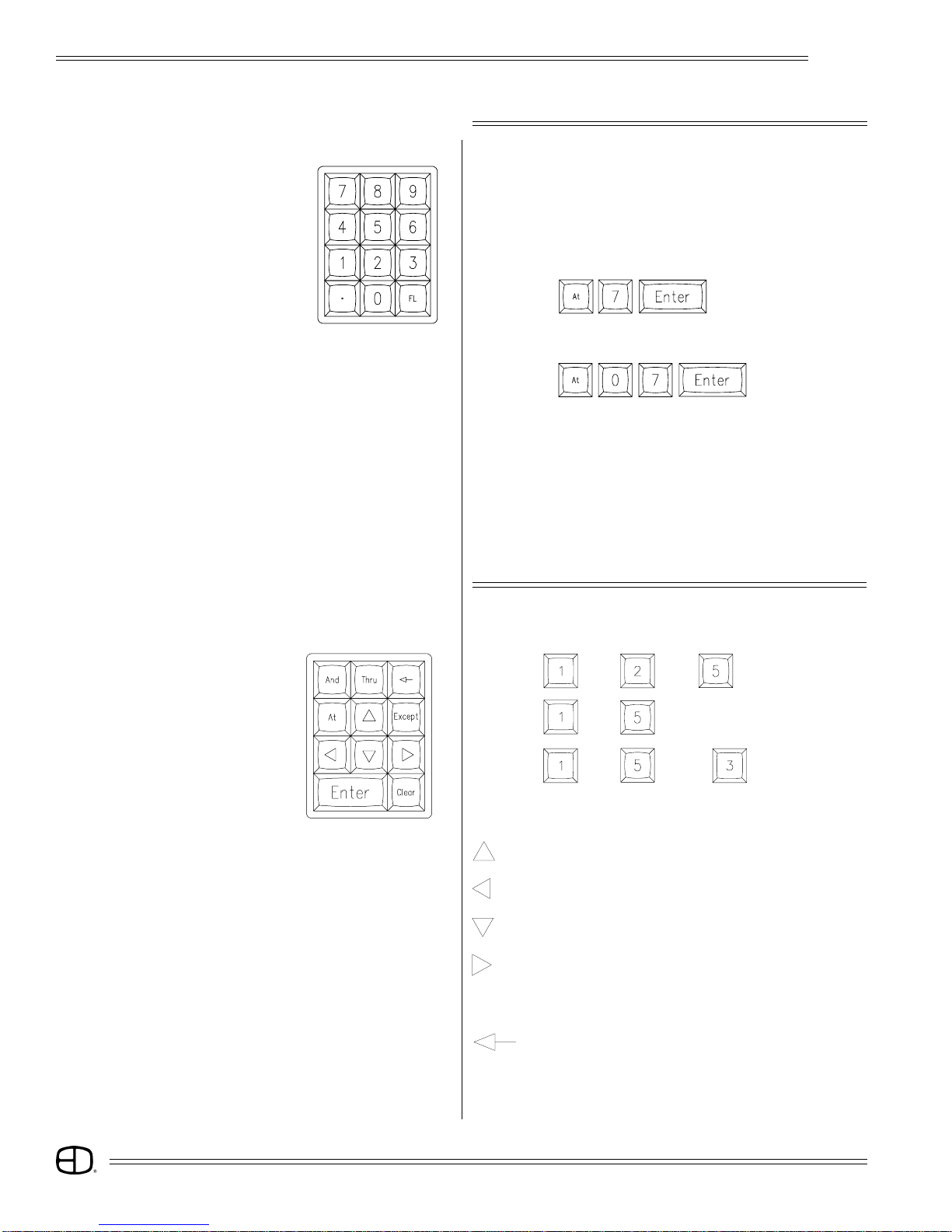
NUMBER KEYS
Numeric and selection keys allow the operator input on the
command line at the base of the CRT display. Numeric keys
are always considered channel numbers unless modified or
introduced by command keys.
NOTE: When addressing levels, a single-digit entry assumes the
number in the ten's column:
will yield at 70.
When two digits are entered, the second number goes to the
one's column:
will yield at 7.
DECIMAL KEY:
Used to insert between whole number cues or to identify tenth
of seconds.
FL KEY:
Full Key: Assigns value of 100%.
SELECTION KEYS
AND: and and
THRU: thru
EXCEPT: thru except
AT: Transition between number keys.
: Moves cursor up.
: Moves cursor to the left.
: Moves cursor down.
: Moves cursor to the right.
ENTER: Accepts and executes command line instruction.
:Backspace removes last entry on Command line.
CLEAR: Clears Command line.
8
Page 9
OVERVIEW
EnAct
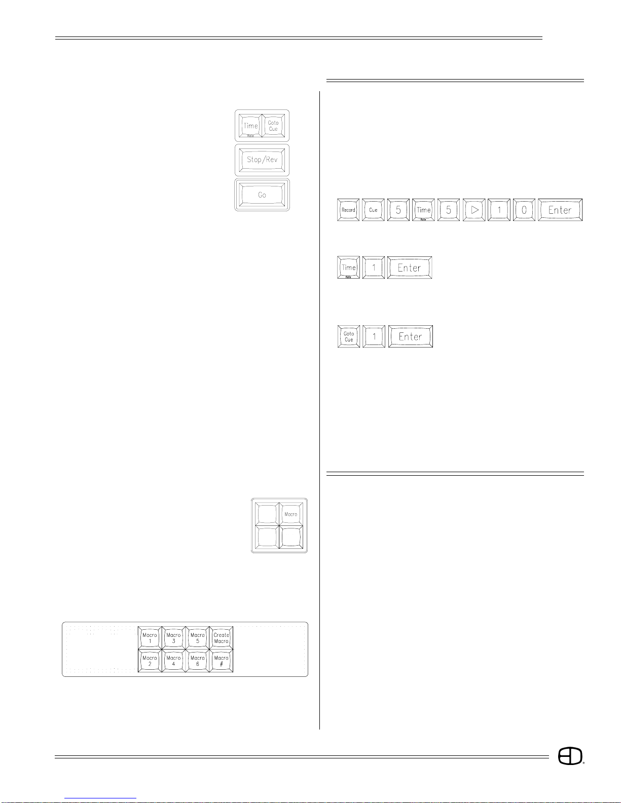
FADER KEYS
Fader keys allow the operator to assign and control the
cues loaded to the faders.Small fader keys require the ENTER
key to complete the action.
Large keys are direct access keys.
TIME:
Can specifiy time for the Go to Cue key. Also can specifiy time
during record cue action.
RATE:
Use Time/Rate key to control fader time with wheel.
allows wheel to control Fader 1.
GO TO CUE:
Routes Stage display to a new position and indicates the next
action on Fader display.
STOP/REVERSE:
When a fade is in progress, pressing STOP will halt all fades. The
second press clears the fader. The third press backs up one cue
on the cue list.
When a fade is not in progress, STOP backs up one cue on the
cue list.
GO:
Starts the Cue action loaded in the Fader window.
MACRO KEYS
Macro keys are designed to allow the operator a method
of tailoring the console to individual performance needs.
Common, repetative keystrokes can be recorded together to
be replaced under a single keystroke.
The MACRO Screen key allows the operator to review or
edit any macro created. Macros can also be labeled with a
name for easy identification.
MACRO KEY:
Displays Macro Screen (see page 44.)
MACRO 1-6:
Single key access to the recorded Macro.
CREATE MACRO:
Used to open and close the Macro record process. Any keyhits
after Create Macro is pressed will automatically be recorded as
part of the Macro.
MACRO #:
Allow access to Macros greater than 6. Press Macro#, number
and ENTER to access a larger Macro number.
9
Page 10
OVERVIEW
EnAct
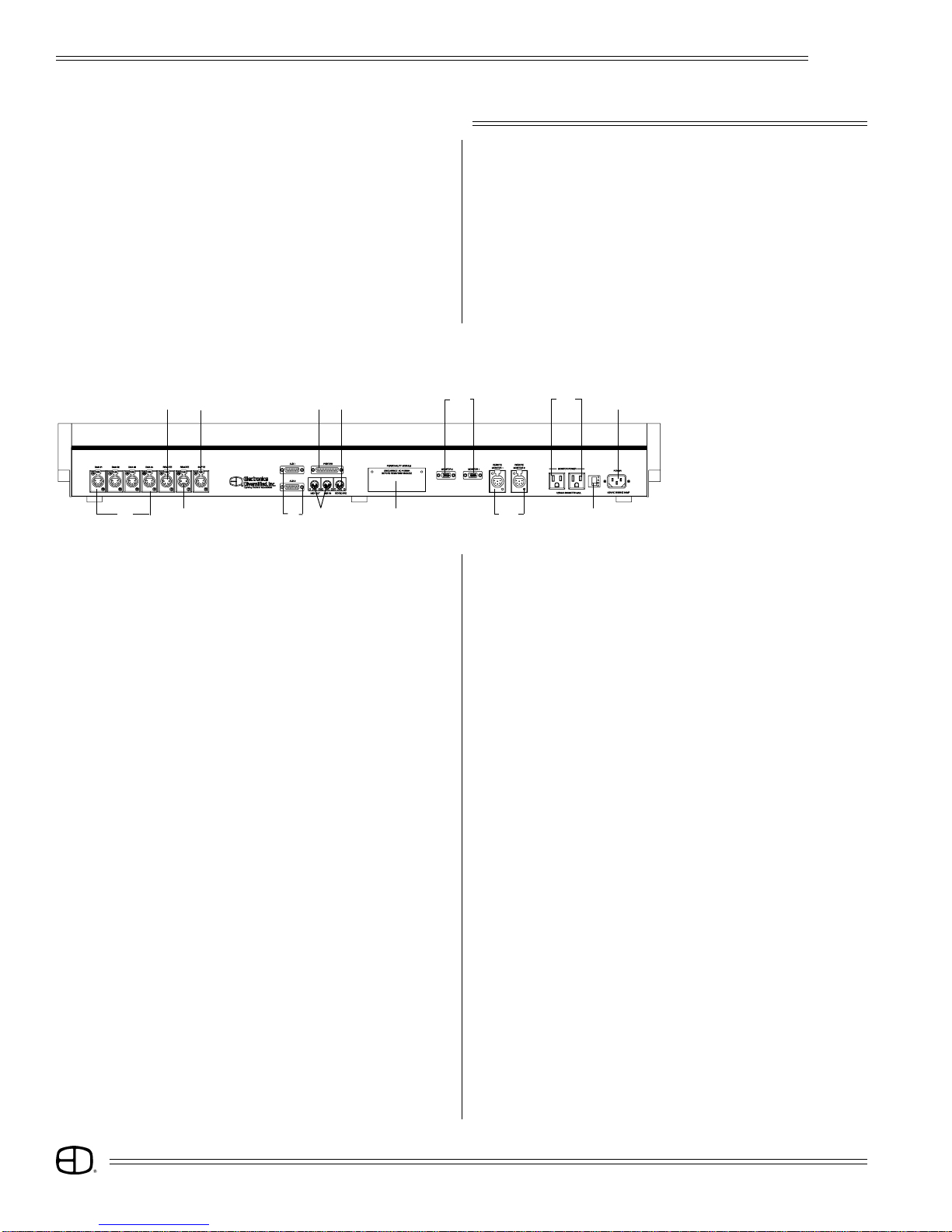
REAR PANEL
The function of each output connector on the rear of the
console is indicated below. Control cables furnished with the
console mate these outputs to the system connection plates
in the facility. All XLR connectors are keyed, locking connectors.
Position carefully at the receptacle, rotate until the connector
mates to the keyed position, then insert.
All 'D' series connectors require the thumb screws
associated with the male end to be tightened to insure proper
connection. Do not force connectors into position
2
1
3 5 7
6 84
9
10
11
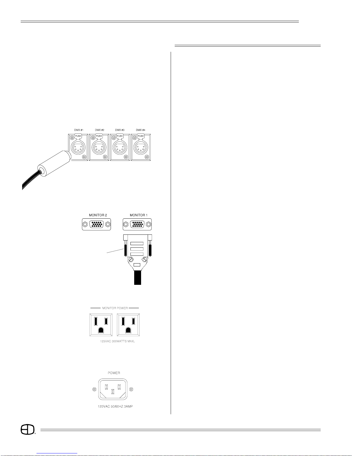
01. FOUR DMX OUTPUTS (5-pinXLR)
02. HAND-HELD REMOTE (4-pin XLR)
03. DESIGNER'S REMOTE (4-pin XLR)
04. TIMED ACTIONS INPUT (optional) (3-pin XLR)
05. AUXILIARY SERIAL PORTS (Type DB15)
06. PRINTER OUTPUT (Type DB25)
07. MIDI IN & OUT (optional)
08. PC KEYBOARD (optional)
09. PERSONALITY MODULE (software update access)
10. VIDEO MONITORS (VGA standard disconnect)
11. REMOTE VIDEO (6-pin XLR)
12. MONITOR CONVENIENCE OUTLETS (300W max.)
13. FUSE (3 Amp)
14. POWER INPUT (92 to 235 VAC, 47/64 Hz, 3 Amp)
12
DMX #1 - Dimmers 1 to 512 (Standard)
DMX #2 - Dimmers 512 to 1024 (Standard)
DMX #3 - Dimmers 1025 to 1536 (Optional)
DMX #4 - Dimmers 1537 to 2048 (Optional)
14
13
10
Page 11

OVERVIEW
EnAct
SIDE PANEL
Indicator Light
Write-protect Tab
Disk Drive
Eject Button
The EnAct control console is a disk-based control system.
All control information set in place by the operator is
automatically saved in random access memory inside the
console. In addition, the information can be saved and stored
off-line for future use on a 1.44MB, 3.5" high-density disk. The
disk drive is located on the right side of the console.
Access to the disk drive features is available through menu
selections on the Setup display. Follow the simple disk handling
procedures outlined below to insure proper operation. All
disks must be formatted before use. Check the label on the
disk. If the disk is not formatted, follow the instructions below.
3.5" Disk
DISK HANDLING PROCEDURE:
DISK DRIVE: 3.5" IBM format, 1.44MB.
Disks must be formatted by the EnAct console before use.
1. Insert the diskette as illustrated. Do not force it into the drive. If
the diskette will not insert easily, it is not correctly oriented.
2. To eject the diskette, push the small button on the disk drive.
3. Ensure that diskettes are handled in the following manner:
Do not expose to high temperatures.
Do not store near magnetic fields.
NOTE: Never eject a diskette while the disk drive indicator light is
on. This could result in loss of data or incomplete loading
of a show. Wait until the indicator light goes off before
ejecting.
Metal Flap
Write-protect Tab
SETUP Version 2.3 Grandmaster FL 9:01:00
MAIN MENU
1> System
2> Cues
3> Submaster
4> Patch
5> Front Panel
6> Save to Disk Functions
7> Load from Disk Functions
8> Print Functions
9> Clear Functions
10> Time Functions
11> Peripherals / Utilities
Enter:
WRITE PROTECTION:
1. Orient the diskette so that the round metal circle is pointed
toward you.
2. With the metal flap on top, the write-protect tab is located in the
lower right-hand corner.
If this tab is closed, the diskette is not Write Protected.
If the tab is open, the diskette is Write Protected, and no new
data can be written in.
FORMAT A DISK
INSERT DISK TO BE FORMATTED INTO DISK DRIVE:
Press SETUP: The Main Menu will appear on the screen.
SELECT PERIPHERALS/UTILITIES MENU:
Press
SELECT FORMAT DISK:
Press
Press
line will prompt "Format Complete."
again. The console will erase any information
on the disk and format the disk for use with
the console. When completed, the command
Press any key to select the next display.
The Peripherals/UtilitiesMenu
will appear on the screen.
The Command Line will
respond with "Are You Sure?"
11
Page 12
SYSTEM SETUP
EnAct
START UP
The EnAct is a microprocessor-based control console
sensitive to power fluctuations on standard power lines. As a
minimum, the console should be plugged into an isolated
circuit with a full equipment ground. For best results, the
console should be connected to a UPS power supply, or as
a bare minimum, a high quality power conditioner.
Do not plug the console into an outlet with motor or SCRcontrolled devices.
The steps called out below will guide you through the first
start-up exercise of the EnAct Console.
Follow the directions carefully.
STEP 1:
Position the control console on a flat surface. The key position
in the upper right corner should be Off.
Do not connect the power cable at this time.
STEP 2:
Connect the 5-pin XLR DMX cable into the first DMX output port
on the rear of the console. Connect the opposite end to the
control connection plate labeled DMX or DMX #1. If the system
is equipped with more than 512 dimmers, connect the next DMX
cable to the next appropriate port on both the output of the
console to the control connection plate.
Captive
thumb screws
STEP 3:
Position the SVGA monitor adjacent to the console. Connect the
VGA cable male end with the (15-pin 'D' connector) to the rear of the
monitor. Use the captive thumb screws to tighten the connection.
STEP 4:
Connect the other male end of the VGA cable to the console
video output Monitor 1 (Item 10, page 10). Use the captive
thumb screws to tighten the connection.
STEP 5:
Repeat steps #3 and #4 if the console is a dual SVGA system.
STEP 6:
Connect the recessed female power cord to the rear of the
SVGA monitor.
STEP 7:
Connect the male end of the monitor power cord to the monitor
convenience outlet located on the rear of the console (Item 12,
page 10).
STEP 8:
Repeat steps #6 and #7 if the console is a dual SVGA system.
STEP 9:
Connect the male end of the console power cord to a line
voltage outlet (120VAC, U.S. version or 220VAC, export version).
STEP 10:
Connect the female end of the power cord to the rear of the
console (Item 14, page 10.)
12
Page 13
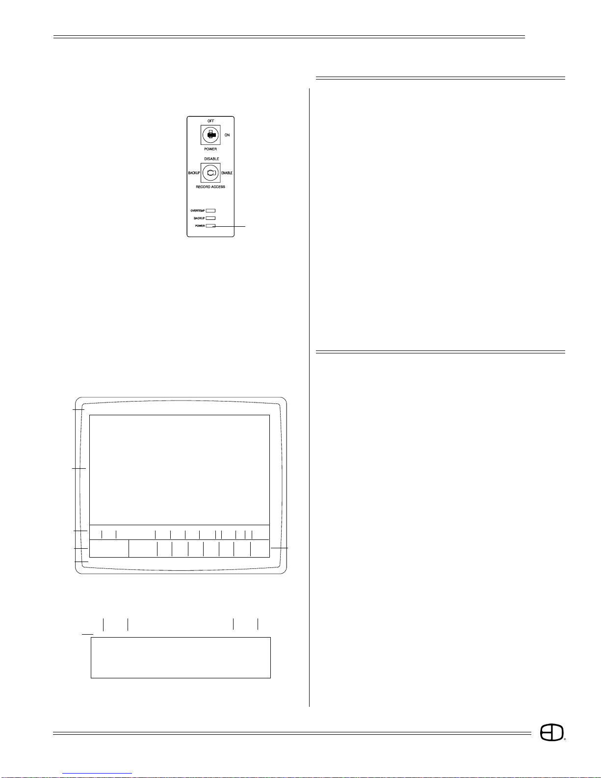
SYSTEM SETUP
Power Light
EnAct
START UP
STEP 11:
Check each connection to insure correct mating. If all connections
are correct, remove the cardboard from the system disk drive,
and insert the formatted disk shipped with the console.
(If necessary, review Side Panel, page 11, for proper orientation of
the system disk prior to insertion).
STEP 12:
You are now ready to power up!
Insert the key into the top position on the front panel. Turn the key
clockwise to the first position.
The POWER light under the key position should come on. In
addition, the tricolored LED's under the bump buttons will cycle.
STEP 13:
Switch the monitor on. The monitor power LED should illuminate.
The Stage Screen should be displayed. Use the monitor controls to position the image in the center of the display screen.
Expand the image to fill the screen. Do not fill the entire screen,
since the console command line will appear below the brown
border on the left side.
The console is ready to operate.
1
STAGE Enact Grandmaster FL 9:01:00
001 02 03 04 05 06 07 0809 10 11 12 13 14 15 16 17 18 19 20 21 22 23 24 25
FL FL FL FL FL 70 70
026 27 28 29 30 31 32 3334 35 36 37 38 39 40 41 42 4344 45 4647 48 49 50
051 52 53 54 55 56 57 5859 60 61 62 63 64 65 66 67 6869 70 7172 73 74 75
076 77 78 79 80 81 82 8384 85 86 87 88 89 90 91 92 9394 95 9697 98 99 00
2
101 02 03 04 05 06 07 0809 10 11 12 13 14 15 16 17 1819 20 2122 23 24 25
126 27 28 29 30 31 32 3334 35 36 37 38 39 40 41 42 4344 45 4647 48 49 50
151 52 53 54 55 56 57 5859 60 61 62 63 64 65 66 67 6869 70 7172 73 74 75
176 77 78 79 80 81 82 8384 85 86 87 88 89 90 91 92 9394 95 9697 98 99 00
S Cue Name Time Delay PF Link EA EB Macro
3
Enter: Fdr: 1 2 3 4 5 6 7 8
4
Channel Level Cue:
Or At %://///// /
6
A
STAGE Enact Grandmaster FL 9:01:001
DISPLAY SCREEN
The display screen is broken up into six basic groups of
information to alert the operator to the current status of
operation.
1. TITLE BLOCK.
2. CHANNEL FIELD.
3. CUE WINDOW.
4. PROMPT WINDOW.
5. FADER WINDOW.
6. COMMAND LINE.
5
CDB
1. TITLE BLOCK:
A. Screen Label: identifies which Display screen is active.
B. Text Label: user addressable space to label the program.
C. Grand Master: indicates the level of the system Grand
Master.
D. Clock: indicates the time of day.
13
Page 14
SYSTEM SETUP
A
001 02 03 04 05 06 07 08 09 10 11 12 13 14 15 16 17 18 19 20 21 22 23 24 25
FL FL FL FL FL 70 70
026 27 28 29 30 31 32 33 34 35 36 37 38 39 40 41 42 4344 45 46 47 48 49 50
051 52 53 54 55 56 57 58 59 60 61 62 63 64 65 66 67 6869 70 71 72 73 74 75
076 77 78 79 80 81 82 83 84 85 86 87 88 89 90 91 92 9394 95 96 97 98 99 00
2
101 02 03 04 05 06 07 08 09 10 11 12 13 14 15 16 17 1819 20 21 22 23 24 25
126 27 28 29 30 31 32 33 34 35 36 37 38 39 40 41 42 4344 45 46 47 48 49 50
151 52 53 54 55 56 57 58 59 60 61 62 63 64 65 66 67 6869 70 71 72 73 74 75
176 77 78 79 80 81 82 83 84 85 86 87 88 89 90 91 92 9394 95 96 97 98 99 00
S Cue Name Time Delay PF Link EA EB Macro
Enter: Fdr: 1 2 3 4 5 6 7 8
Channel Level Cue:
Or At %://// /// /
B
EnAct
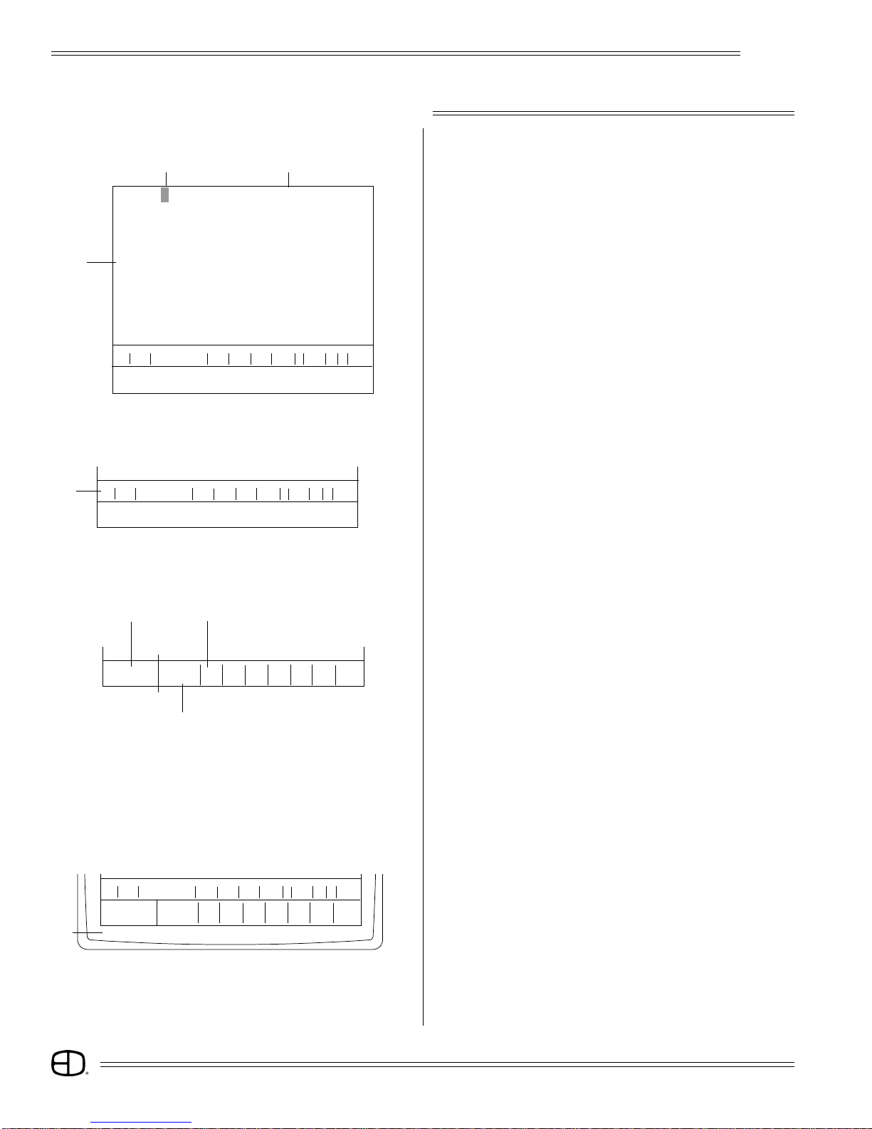
DISPLAY SCREEN
2. CHANNEL SECTION:
A. Reverse video square defaluts to upper left position.
B. Displays up to 200 channels. Levels entered are displayed
below the channel numbers.
S Cue Name Time Delay PF Link EA EB Macro
3
Enter: Fdr: 1 2 3 4 5 6 7 8
Channel Level Cue:
Or At %: / / / / / / / /
4A
Enter: Fdr: 1 2 3 4 5 6 7 8
Channel Level Cue:
Or At %: / / / / / / / /
5
4B
3. CUE WINDOW:
Displays up to 3 sequential cue actions with the active cue
highlighted on the top line.
4. PROMPT SECTION:
A. Prompt Window: On-line prompt suggests what could be the
next action based on command line status.
B. Help Display: Area highlighted with instruction when the
HELP key is selected.
5. FADER WINDOW:
Displays cue loaded to any fader and status of cue.
6. COMMAND LINE:
Displays action to take.
Are You Sure?
6
14
Page 15
STAGE SCREEN
STAGE Enact Grandmaster FL 9:01:00
001 02 03 04 05 06 07 08 09 10 11 12 13 14 15 16 17 18 19 20 2122 23 24 25
026 27 28 29 30 31 32 33 34 35 36 37 38 39 40 41 42 4344 45 46 47 48 49 50
051 52 53 54 55 56 57 58 59 60 61 62 63 64 65 66 67 6869 70 71 72 73 74 75
076 77 78 79 80 81 82 83 84 85 86 87 88 89 90 91 92 9394 95 96 97 98 99 00
101 02 03 04 05 06 07 08 09 10 11 12 13 14 15 16 17 1819 20 21 22 23 24 25
126 27 28 29 30 31 32 33 34 35 36 37 38 39 40 41 42 4344 45 46 47 48 49 50
151 52 53 54 55 56 57 58 59 60 61 62 63 64 65 66 67 6869 70 71 72 73 74 75
176 77 78 79 80 81 82 83 84 85 86 87 88 89 90 91 92 9394 95 96 97 98 99 00
S Cue Name Time Delay PF Link EA EB Macro
Enter: Fd r: 1 2 3 4 5 6 7 8
Channel Level Cue:
Or At %: / / / / / / / /
Screen Colors:
Channel Numbers . . . . . . . . . . . . . . . . . . . . . . . . . . . . . . . . . . . . . Green
Selected Channels . . . . . . . . . . . . . . . . . . . . . . . . . . . . . . . . . . . . Yellow
Manually Set Levels . . . . . . . . . . . . . . . . . . . . . . . . . . . . . . . . . . . Brown
Cue Levels . . . . . . . . . . . . . . . . . . . . . . . . . . . . . . . . . . . . . . . . . . . . White
Group Levels . . . . . . . . . . . . . . . . . . . . . . . . . . . . . . . . . . . . . . . . . Yellow
Submaster Levels . . . . . . . . . . . . . . . . . . . . . . . . . . . . . . . . . . . . . . Blue
Effects Levels . . . . . . . . . . . . . . . . . . . . . . . . . . . . . . . . . . . . . . . . Purple
EnAct
SETTING LEVELS
The Stage Screen offers the operator a real time (live)
output of any system channel addressed. The white cursor
position on the display will move whenever a system channel
is addressed from the keypad. The white cursor represents
the active position on the screen. The cursor defaults to the
top left corner or the first addressable position in any screen.
The numeric keypad is used to address any channel on the
display.
The structure used to address the channels in the Stage
Screen is based on input from the numeric keypad. The first
digits pressed on the keypad are automatically considered
channels numbers unless information exists on the command
line. To insure proper channel address, make sure nothing is
on the command line, or press the CLEAR key before input.
Channel selection is transitioned to level information with
the AT key. The AT key automatically sets the next numeric
entry as level information. The syntax requires an ENTER key
press in order to terminate the statement and execute the
request.
The colors used on the channel display are coded to help
the operator identify the status of any channel in the display.
All channel numbers are displayed in Green.
When a single channel or list of channels are accessed
through the keypad, they are considered selected. Selected
channels display in Yellow.
When selected channels are assigned manually set levels,
the levels are displayed in Brown. Manually set levels stay
brown until they are assigned to either a Cue, Group,
Submaster, or Effect.
Manually set levels not assigned to a Cue, Group,
Submaster or Effect stay brown and block any assigned levels
from appearing on the channel.
The advantage of color coding is simply to alert the
operator to the status of the channel at any time.
Command Line
S Cue Name Time Delay PF Link EA EB Macro
Enter: Fdr: 1 2 3 4 5 6 7 8
Channel Level Cue:
Or At %: / / / / / / / /
10
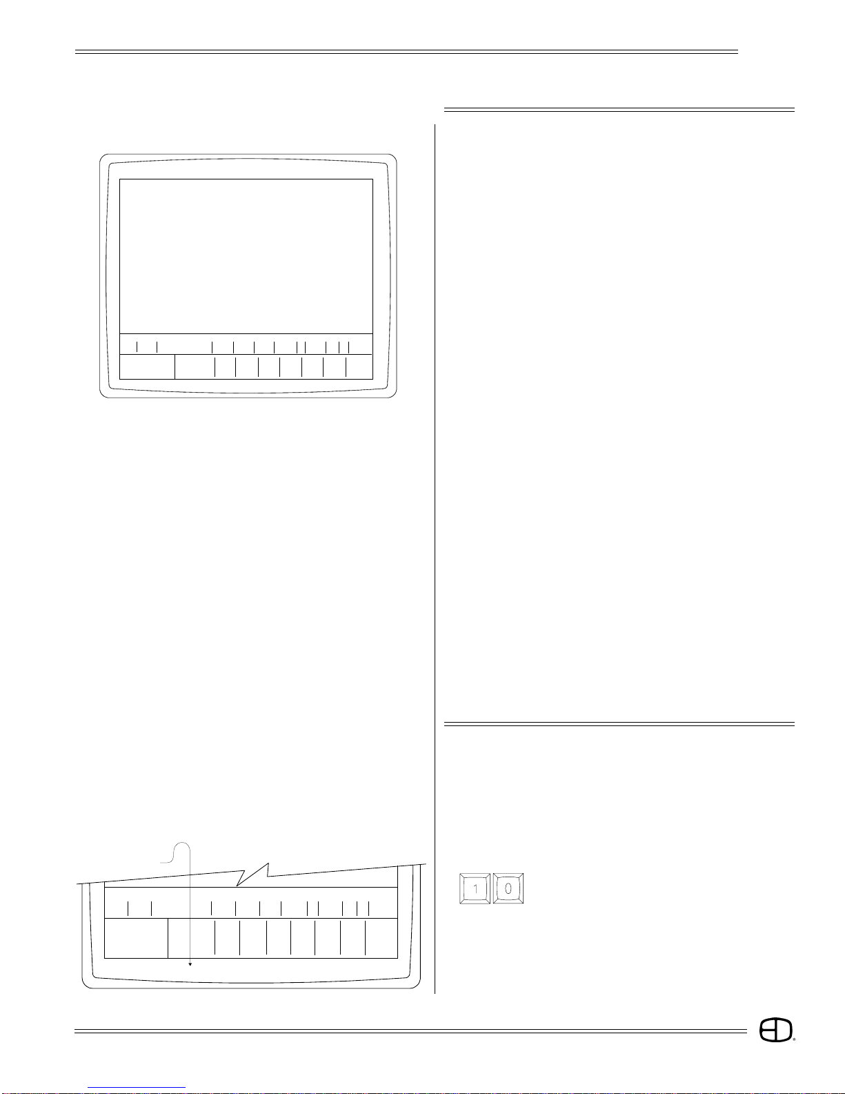
SETTING LEVELS
The following illustrations are designed to familiarize you
with setting levels on the Stage Screen. Note three modes of
information:
Text Instruction Key Presses Results
SELECT CHANNEL 10:
Press
Notice that channel 10 is called out on the command line, but not
highlighted on the screen.
15
Page 16
STAGE SCREEN
STAGE Enact Grandmaster FL 9:01:00
001 02 03 04 05 06 07 08 09 10 11 12 13 14 15 16 17 18 19 20 21 22 23 24 25
026 27 28 29 30 31 32 33 34 35 36 37 38 39 40 41 42 4344 45 46 47 48 49 50
051 52 53 54 55 56 57 58 59 60 61 62 63 64 65 66 67 6869 70 71 72 73 74 75
076 77 78 79 80 81 82 83 84 85 86 87 88 89 90 91 92 9394 95 96 97 98 99 00
101 02 03 04 05 06 07 08 09 10 11 12 13 14 15 16 17 1819 20 21 22 23 24 25
126 27 28 29 30 31 32 33 34 35 36 37 38 39 40 41 42 4344 45 46 47 48 49 50
151 52 53 54 55 56 57 58 59 60 61 62 63 64 65 66 67 6869 70 71 72 73 74 75
176 77 78 79 80 81 82 83 84 85 86 87 88 89 90 91 92 9394 95 96 97 98 99 00
S Cue Name Time Delay PF Link EA EB Macro
Enter: Fdr: 1 2 3 4 5 6 7 8
Channel Level Cue:
Or At %: / / / / / / / /
15
EnAct
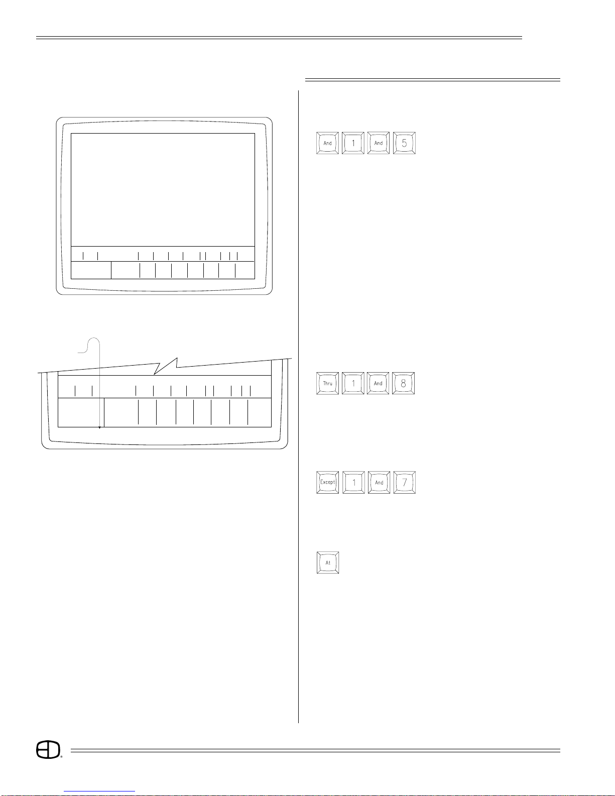
SETTING LEVELS
SELECT MORE THAN ONE CHANNEL:
Press
Note that channel 10 is highlighted Yellow and 15 is on the
command line. The [AND] key forceds the previous selection to be
highlighted.
Command Line
S Cue Name Time Delay PF Link EA EB Macro
Enter: Fdr: 1 2 3 4 5 6 7 8
Channel Level Cue:
Or At %: / / / / / / / /
Thru 1 and 8
SELECT A LIST OF CONSECTUTIVE CHANNELS:
Press
Notice that channel 15 is now highlighted, but the cursor does not
move unitl a bridge key like [AND], [THRU], and [EXCEPT] are
used. If you want to end the selection process, press AT and all
channels called out on the command line will be highlighted.
REMOVE A CHANNEL FROM THE CONSECTUTIVE LIST:
Press
Notice that channels 16, 17, and 18 are highlighted Yellow.
MAKE A TRANSITION BETWEEN CHANNEL SELECTION AND
LEVEL ASSIGNMENT:
Press
Notice that channel 17 is no longer highlighted Yellow, but restored
to Green.
16
Page 17
STAGE SCREEN
EnAct
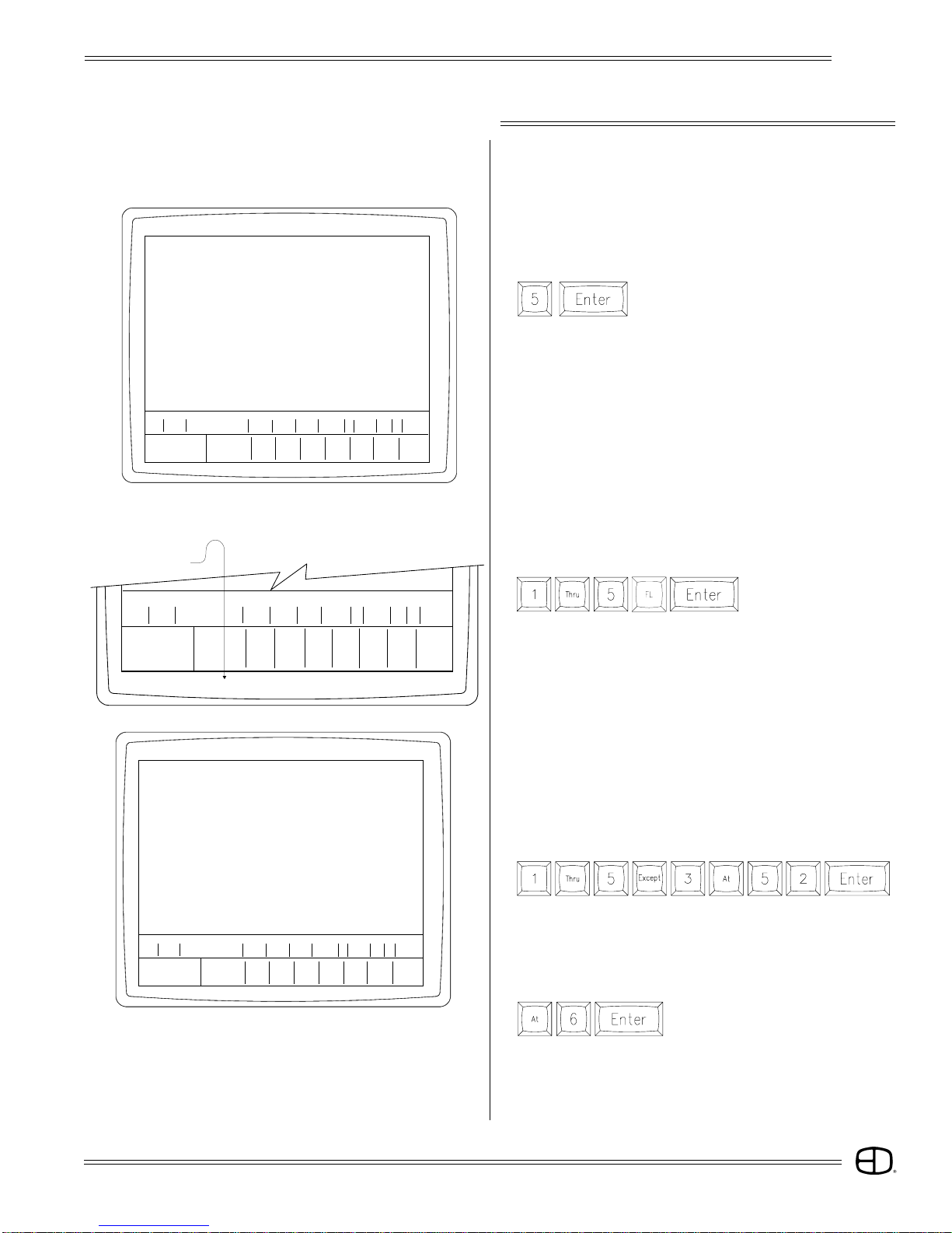
SETTING LEVELS
ASSIGN A LEVEL TO THE SELECTED CHANNELS HIGHLIGHTED:
Press any numeric value on the keypad.
STAGE Enact Grandmaster FL 9:01:00
001 02 03 04 05 06 07 08 09 10 11 12 13 14 15 16 17 18 19 20 21 22 23 24 25
026 27 28 29 30 31 32 33 34 35 36 37 38 39 40 41 42 4344 45 46 47 48 49 50
051 52 53 54 55 56 57 58 59 60 61 62 63 64 65 66 67 6869 70 71 72 73 74 75
076 77 78 79 80 81 82 83 84 85 86 87 88 89 90 91 92 9394 95 96 97 98 99 00
101 02 03 04 05 06 07 08 09 10 11 12 13 14 15 16 17 1819 20 21 22 23 24 25
126 27 28 29 30 31 32 33 34 35 36 37 38 39 40 41 42 4344 45 46 47 48 49 50
151 52 53 54 55 56 57 58 59 60 61 62 63 64 65 66 67 6869 70 71 72 73 74 75
176 77 78 79 80 81 82 83 84 85 86 87 88 89 90 91 92 9394 95 96 97 98 99 00
S Cue Name Time Delay PF Link EA EB Macro
Enter: Fdr: 1 2 3 4 5 6 7 8
Channel Level Cue:
Or At %: / / / / / / / /
15
50 50 50
Command Line
S Cue Name Time Delay PF Link EA EB Macro
Enter: Fdr: 1 2 3 4 5 6 7 8
Channel Level Cue:
Or At %: / / / / / / / /
1 thru 5 at FL
(You can press a single digit and ENTER for a 10's value, or a
double digit and ENTER for a 10's and 1's value.)
Press
Notice that the channels are no longer highlighted and the values
are set at 50 in Brown.
Try the selection again. This time, make a complete statement
which includes the channel address and the level command.
Watch the command line carefully. If you miss a key or hit the wrong
key, use the backspace arrow in the upper right hand corner of the
numeric keypad to correct the command line.
SET CHANNELS 1 THROUGH 5 TO FULL:
Press
Note that all channels are set at the same levels.
STAGE Enact Grandmaster FL 9:01:00
001 02 03 04 05 06 07 0809 10 11 12 13 14 15 16 17 18 19 20 21 22 23 24 25
FL FL FL FL FL
026 27 28 29 30 31 32 3334 35 36 37 38 39 40 41 42 43 44 45 46 47 48 49 50
051 52 53 54 55 56 57 5859 60 61 62 63 64 65 66 67 68 69 70 71 72 73 74 75
076 77 78 79 80 81 82 8384 85 86 87 88 89 90 91 92 93 94 95 96 97 98 99 00
101 02 03 04 05 06 07 0809 10 11 12 13 14 15 16 17 18 19 20 21 22 23 24 25
126 27 28 29 30 31 32 3334 35 36 37 38 39 40 41 42 43 44 45 46 47 48 49 50
151 52 53 54 55 56 57 5859 60 61 62 63 64 65 66 67 68 69 70 71 72 73 74 75
176 77 78 79 80 81 82 8384 85 86 87 88 89 90 91 92 93 94 95 96 97 98 99 00
S Cue Name Time Delay PF Link EA EB Macro
Enter: Fdr: 1 2 3 4 5 6 7 8
Channel Level Cue:
Or At %://// /// /
SET CHANNELS 1, 2, 4 and 5 AT 52%. LEAVE CHANNEL 3 AT
FULL:
Press
Notice that channels not included in the string are not disturbed by
the commands.
CHANGE LEVEL TO 60% OF LAST SELECTED CHANNELS,
WHEN THE CURSUR HAS NOT MOVED:
Press
Notice that the last channels can be re-captured for address again
without entry by simply pressing the AT key. The channels will be
highlighted and ready to receive a new level command.
17
Page 18

STAGE SCREEN
STAGE Enact Grandmaster FL 9:01:00
001 02 03 04 05 06 07 08 09 10 11 12 13 14 15 16 17 18 19 20 21 22 23 24 25
52 52 FL 52 52
026 27 28 29 30 31 32 3334 35 36 37 38 39 40 41 42 4344 45 4647 48 49 50
051 52 53 54 55 56 57 5859 60 61 62 63 64 65 66 67 6869 70 7172 73 74 75
076 77 78 79 80 81 82 8384 85 86 87 88 89 90 91 92 9394 95 9697 98 99 00
101 02 03 04 05 06 07 0809 10 11 12 13 14 15 16 17 1819 20 2122 23 24 25
126 27 28 29 30 31 32 3334 35 36 37 38 39 40 41 42 4344 45 4647 48 49 50
151 52 53 54 55 56 57 5859 60 61 62 63 64 65 66 67 6869 70 7172 73 74 75
176 77 78 79 80 81 82 8384 85 86 87 88 89 90 91 92 9394 95 9697 98 99 00
S Cue Name Time Delay PF Link EA EB Macro
Enter: Fd r: 1 2 3 4 5 6 7 8
Channel Level Cue:
Or At %: / / / / / / / /
EnAct
SETTING LEVELS
ACCESS WHEEL CONTROL:
Channel numbers with assigned levels can be controlled by the
wheel. To access level wheel control, follow the steps below:
Press
Raise or lower the Wheel. (Selected channels are Yellow).
TO RELEASE CHANNELS FRO LEVEL WHEEL CONTROL:
Press
Notice that the channel numbers are no longer highlighted and
wheel is inactive.
TO ACCESS THE SAME CHANNELS AND RESET THE LEVELS:
Press
Previous channels are selected again and controlled by the level
wheel.
TO RELEASE THE CHANNELS WITH THE LEVELS SET FROM
THE LEVEL WHEEL:
Press
Channels are released and levels are set.
TO CLEAR THE LAST SET OF CHANNELS AND SET THE LEVELS
TO NULL VALUES:
Press
STAGE Enact Grandmaster FL 9:01:00
001 02 03 04 05 06 07 08 09 10 11 12 13 14 15 16 17 18 19 20 21 22 23 24 25
026 27 28 29 30 31 32 33 34 35 36 37 38 39 40 41 42 43 44 45 46 47 48 49 50
051 52 53 54 55 56 57 58 59 60 61 62 63 64 65 66 67 68 69 70 71 72 73 74 75
076 77 78 79 80 81 82 83 84 85 86 87 88 89 90 91 92 93 94 95 96 97 98 99 00
101 02 03 04 05 06 07 08 09 10 11 12 13 14 15 16 17 18 19 20 21 22 23 24 25
126 27 28 29 30 31 32 33 34 35 36 37 38 39 40 41 42 43 44 45 46 47 48 49 50
151 52 53 54 55 56 57 58 59 60 61 62 63 64 65 66 67 68 69 70 71 72 73 74 75
176 77 78 79 80 81 82 83 84 85 86 87 88 89 90 91 92 93 94 95 96 97 98 99 00
S Cue Name Time Delay PF Link EA EB Macro
Enter: Fd r: 1 2 3 4 5 6 7 8
Channel Level Cue:
Or At %: / / / / / / / /
Notice that the levels disappeared and the level field is blank.
Blanks, or null values are different from zeroes.
RESTORE KEY:
If AT, ENTER is pressed by mistake, or the levels have been
changed and need to be recalled at a previous value, use the
RESTORE key to recall the last levels set prior to the AT, ENTER
keystrokes.
Press
Notice that the levels are restored without the use of the ENTER
key. RESTORE is an Action key that does not require the ENTER
key to complete the action. RESTORE will only 'recall' one instruction
set prior to the ENTER key.
18
Page 19

STAGE SCREEN
STAGE Enact Grandmaster FL 9:01:00
001 02 03 04 05 06 07 08 09 10 11 12 13 14 15 16 17 18 19 20 21 22 23 24 25
52 52 FL 52 52
026 27 28 29 30 31 32 33 34 35 36 37 38 39 40 41 42 43 44 45 46 47 48 49 50
051 52 53 54 55 56 57 58 59 60 61 62 63 64 65 66 67 68 69 70 71 72 73 74 75
076 77 78 79 80 81 82 83 84 85 86 87 88 89 90 91 92 93 94 95 96 97 98 99 00
101 02 03 04 05 06 07 08 09 10 11 12 13 14 15 16 17 18 19 20 21 22 23 24 25
126 27 28 29 30 31 32 33 34 35 36 37 38 39 40 41 42 43 44 45 46 47 48 49 50
151 52 53 54 55 56 57 58 59 60 61 62 63 64 65 66 67 68 69 70 71 72 73 74 75
176 77 78 79 80 81 82 83 84 85 86 87 88 89 90 91 92 93 94 95 96 97 98 99 00
S Cue Name Time Delay PF Link EA EB Macro
Enter: Fdr: 1 2 3 4 5 6 7 8
Channel Level Cue:
Or At %: / / / / / / / /
EnAct
SETTING LEVELS
TO SET NULL LEVELS:
Another way to set a manually selected channel's level to null is
to follow the sequence below:
Press
Channel 20 is set with a level of 50.
Now, Press
Notice that if a channel is selected without a value, the ENTER key
moves the selected channel from the highlighted field.
CHANNEL CONTROL:
All the channels can be selected and controlled by the level
wheel in the following sequence:
Press
Notice that all the channel numbers are highlighted
Any channel with a level assigned can be adjusted by the level
wheel. Move the wheel up.
Again, notice that all channels move together
TO RELEASE SELECTED CHANNELS AT THE NEW LEVELS:
Press
or
Notice that the channels are no longer highlighted and the levels
are set. CLEAR is the ideal key to use since it clears the command
lline. The BACKSPACE key can accomplish the same goal, however,
it requires more key strokes.
TO RETURN TO THE PREVIOUS VALUES PRIOR TO THE
LEVEL WHEEL ADJUSTMENT:
Press
Notice that the levels changed to the previous setting.
TO ELIMINATE ASSIGNED CHANNEL LEVELS:
Press
This response is similar to the keystrokes AT, ENTER. The primary
difference is AT ENTER eliminates the levels assigned to the
highlighted channels while ENTER, ENTER selects all the channels
with the first ENTER. If you accidently press ENTER, ENTER, you
can return the channels to the previous levels by pressing the
RESTORE Key.
19
Page 20

STAGE SCREEN
EnAct
SETTING LEVELS
REM DIM KEY:
This is another Action key useful in setting and modifying levels.
REM DIM forces forces all other channels except those on the
command line to zero:
Press
Notice that all other channels were forced to a zero output. You can
always press [RESTORE] to recall the previous channels with their
assigned values.
SUMMARY:
Setting levels is a basic function of the numeric and
selection keypads. The syntax used to assign levels to channels
is very straightforward. The first digits are always channels
numbers. The AT key is used to bridge between channels and
levels. All command line instructions end with the ENTER key.
Sometimes it may be helpful to repeat the syntax out loud
as you perform the keystrokes. Keep your eye on the command
line at the base of the display as you make the keystrokes.
Take your time with the keystrokes to insure the correct
keyhits until you feel comfortable with the structure.
The procedure for setting levels is the same in the Group,
Submaster, and Preview Screens.
Fader Window
S Cue Name Time Delay PF Link EA EB Macro
Enter: Fdr: 1 2 3 4 5 6 7 8
Channel Level Cue:
Or At %: / / / / / / / /
MERGE, INSERT
PILE ON SOURCE LEVELS ONTO EXISTING STAGE LEVELS:
Press
or or (enter number)
Highest levels (source or stage) takes precedence.
IMPOSE SOURCE LEVELS ONTO EXISTING STAGE LEVELS:
Press
or or (enter number)
Source levels take precedence over existing stage levels.
GROUP 1 INSERTED TO 50%:
Press
SUBMASTER 1 INSERTED TO 70%:
Press
20
Page 21

STAGE SCREEN
Cue
Window
S Cue Name Time Delay PF Link EA EB Macro
P 10
Enter: Fdr: 1 2 3 4 5 6 7 8
Channel Level Cue:
Or At %: / / / / / / / /
S Cue Name Time Delay PF Link EA EB Macro
P 8 4
Enter: Fdr: 1 2 3 4 5 6 7 8
Channel Level Cue:
Or At %: / / / / / / / /
Title
S Cue Name Time Delay PF Link EA EB Macro
10 House Lights
Enter: Fdr: 1 2 3 4 5 6 7 8
Channel Level Cue:
Or At %: / / / / / / / /
EnAct
RECORDING CUES
Recording Cues in the Stage Screen. If the setup switch
"Recording in fast mode" is enabled (System menu, #5, page
39), recording is as follows:
TO RECORD CUE 10:
Press
RECORD CUE 8 WITH TIME OF 4:
Press
To change the times or any other attributes, press TIME after cue
number. The cursor will move to the uptime position. To move
about, use the TIME key or the cursor keys.
Any ENTER press will finish the record.
Attributes: (Use SELECT key to toggle through options).
P = Preset: All channels without levels assume Zero.
AT = Autostart & Tracking: Cue will start when the previous
one finishes. Cue is tracking.
AP = Autostart & Preset: Cue will start when the previous
one finishes. Cue is a preset.
MT = Multipart & Tracking: The cue will load onto a fader at
the same time as the cue before it.
T = Tracking: All channels without levels can have levels
track into them from previous cues.
Name: Any 16-character name.
Time: Up Time: The time levels going up will take.
Down Time: The time levels going down will take.
Delay: Up Delay: The wait before Up Time.
Down Delay: The wait before Down Time.
PF: (Preferred Fader): The fader the cue will load into.
Otherwise the cue will load into the lowest available.
Link: The cue to load after this fade is done. Otherwise,
assumes next sequential cue.
EA: (Effect A) Effect that will run while cue is running or last
to run.
EB: (Effect B) Effect that will run while cue is running or last
to run.
Macro:Macro initiated when the cue starts its Up or Down
Time,whichever is first.
LABEL CUE:
Cursor to Name. From optional keyboard, type Name.
When complete, press ENTER.
SET TIME TO 15 SECONDS:
Press
or
21
Page 22

STAGE SCREEN
Time
S Cue Name Time Delay PF Link EA EB Macro
10 House Lights
Enter: Fdr: 1 2 3 4 5 6 7 8
Channel Level Cue:
Or At %: / / / / / / / /
EnAct
RECORDING CUES
TO SPLIT TIMES SO UP FADES ARE 30 AND DOWN FADES
ARE 50:
Press
Note: On up fade, use SELECT to make cue load on a manual
handle automatically.
Note: Delays happen after GO, and before cue fade times.
PF
S Cue Name Time Delay PF Link EA EB Macro
10 House Lights 3 105.4
Enter: Fdr: 1 2 3 4 5 6 7 8
Channel Level Cue:
Or At %: / / / / / / / /
Effects
S Cue Name Time Delay PF Link EA EB Macro
P 10 House Lights 3 105.4 5 7
Enter: Fdr: 1 2 3 4 5 6 7 8
Channel Level Cue:
Or At %: / / / / / / / /
Macro
S Cue Name Time Delay PF Link EA EB Macro
10 House Lights 3 105.4 5 7 87
Enter: Fdr: 1 2 3 4 5 6 7 8
Channel Level Cue:
Or At %: / / / / / / / /
SET THE CUE TO OPERATE ON FADER 3:
Cursor to PF (Preferred Fader)
SET A CUE TO GO TO CUE 105.4 WHEN FADE IS DONE:
Cursor to Link
RUN EFFECTS 5 AND 7 WITH CUE:
Cursor to EA
The effect starts when the cue containing the effect number is
faded and the effect stops when a cue containing another effect or
no effect is faded.
START MACRO 87 WHEN CUE STARTS FADING:
Cursor to MACRO
RECORD CUE 9 WITHOUT ANY SUBMASTERS:
Press
RECORD CUE 7 WITHOUT AFFECTING THE NEXT TRACKING
CUE:
Press
If setup switch "Record in Fast Mode" is set to No, the action:
will place the cursor in the attribute window. A double ENTER
needs to be done to finish record.
FINISH RECORDING A CUE BY JUMPING OUT OF RECORD
WINDOW.
After entering a value, press ENTER again, or JUMP or RECORD.
JUMP OUT WITHOUT RECORDING CUE:
Press
(or any screen key.)
22
Page 23

STAGE SCREEN
STAGE Enact Grandmaster FL 9:01:00
001 02 03 04 05 06 07 08 09 10 11 12 13 14 15 16 17 18 19 20 2122 23 24 25
FL FL FL FL FL 70 70
026 27 28 29 30 31 32 3334 35 36 37 38 39 40 41 42 43 44 45 46 47 48 49 50
051 52 53 54 55 56 57 5859 60 61 62 63 64 65 66 67 68 69 70 71 72 73 74 75
076 77 78 79 80 81 82 8384 85 86 87 88 89 90 91 92 93 94 95 96 97 98 99 00
101 02 03 04 05 06 07 0809 10 11 12 13 14 15 16 17 18 19 20 21 22 23 24 25
126 27 28 29 30 31 32 3334 35 36 37 38 39 40 41 42 43 44 45 46 47 48 49 50
151 52 53 54 55 56 57 5859 60 61 62 63 64 65 66 67 68 69 70 71 72 73 74 75
176 77 78 79 80 81 82 8384 85 86 87 88 89 90 91 92 93 94 95 96 97 98 99 00
S Cue Name Time Delay PF Link EA EB Macro
Enter: Fdr: 1 2 3 4 5 6 7 8
Channel Level Cue:
Or At %://// /// /
Are you sure?
EnAct
MODIFYING CUES
DELETE CUE 8:
Press
"Are you sure?"
CHANGE TIME OF THE CUE ON STAGE TO 6:
Press
PROPORTIONALLY RAISE/LOWER ALL ACTIVE CHANNELS
IN ANY CUE:
Press
Use the Wheel to roll to desired level.
Command Line
Group Window
Group Name
15 House Lights
Enter: Fdr: 1 2 3 4 5 6 7 8
Channel Number Cue:
Or At %:
--/--S / / / / / / /
To proportionally lower all active channels to 80% in any cue, use
the Grand Master Handle.
Lower handle so GM level reads '80'.
ADD CHANGES TO THE CUE ON STAGE:
Press
or
ADD CHANGES TO THE CUE ON STAGE WITH CHANGES TO
APPLY ONLY TO THIS CUE:
Press
RECORDING GROUPS
Recording Groups from the Stage Screen. Set levels for
channels.
RECORD GROUP 15:
Press
TO LABEL GROUP:
Press
From optional keyboard, type name. When complete, press ENTER.
FINISH RECORDING GROUP WHEN "RECORD IN FAST
MODE" IS NO:
Press ENTER again, or JUMP or RECORD.
23
Page 24

STAGE SCREEN
Submaster Window
Sub Name In Dwell Out Mode Source
105 House Lights Manual
Enter: Fdr: 1 2 3 4 5 6 7 8
Sub Number Cue:
%:
--/--S / / / / / / /
EnAct
RECORDING SUBMASTERS
If the setup switch "Recording in fast mode" is enabled
(System menu, #5, page 39), recording is as follows:
RECORD SUBMASTER 105 (page 1, handle 5):
Press
NOTE: If no page is given, Page 1 is assumed.
RECORD SUBMASTER 206 (page 2, handle 6):
Press
To change the times or any other attributes, press TIME after
submaster number. The cursor will move to the up-time position.
To move about use the TIME key or the curson keys.
Any ENTER press will finish the record.
Attributes: (Use SELECT key to toggle through options).
Name: Any 16-character name.
In: For timed submasters. The time it takes to simulate
a handle movement from zero to full.
Dwell: For timed submasters. The time the simulated
handle is at full.
Out: For timed submasters. The time it takes for the
simulated handle to move back to zero.
Mode: Manual: Sub follows handle, bump button takes
handle to level set in setup.
Timed: Sub simulates an up, dwell and down
handle movement. Bump button starts and
pauses.
Advancing: When sub level moves above zero then back, the
sub page number will automatically advance to
the next valid submaster. Can be manual or timed.
Disabled: Sub does nothing.
Source: Indicates where submaster was recorded.
Submaster Label
Sub Name In Dwell Out Mode Source
105 House Lights Manual
Enter: Fdr: 1 2 3 4 5 6 7 8
Sub Number Cue:
5
%:
--/--S / / / / / / /
RECORD SUB 108 (with In and Out time of 5 and zero Dwell):
Press
RECORD SUB 103 AS ADVANCING:
Press
Cursor to Mode and use SELECT to
find Advancing, then ENTER.
LABEL SUBMASTER:
Cursor to Name. From optional keyboard, type name. When
complete, press ENTER on control keypad.
CHANGE OR ADD TIMES:
Cursor to position or press TIME, then enter UP, DWELL,
DOWN times.
24
Page 25

STAGE SCREEN
EnAct
LOAD AND RUN CUES
Load & Run Cues from the Stage Screen:
STAGE Enact Grandmaster FL 9:01:00
001 02 03 04 05 06 07 08 09 10 11 12 13 14 15 16 17 18 19 20 21 22 23 24 25
FL FL FL FL FL 70
026 27 28 29 30 31 32 33 34 35 36 37 38 39 40 41 42 43 44 45 46 47 48 49 50
051 52 53 54 55 56 57 58 59 60 61 62 63 64 65 66 67 68 69 70 71 72 73 74 75
076 77 78 79 80 81 82 83 84 85 86 87 88 89 90 91 92 93 94 95 96 97 98 99 00
101 02 03 04 05 06 07 08 09 10 11 12 13 14 15 16 17 18 19 20 21 22 23 24 25
126 27 28 29 30 31 32 33 34 35 36 37 38 39 40 41 42 43 44 45 46 47 48 49 50
151 52 53 54 55 56 57 58 59 60 61 62 63 64 65 66 67 68 69 70 71 72 73 74 75
176 77 78 79 80 81 82 83 84 85 86 87 88 89 90 91 92 93 94 95 96 97 98 99 00
S Cue Name Time Delay PF Link EA EB Macro
Enter: Fdr: 1 2 3 4 5 6 7 8
Channel Level Cue:
Or At %: --/--s / / / / / / /
ALL CHANNELS MOVE TO ZERO: (Blackout: Time Zero)
Press
All channels move to zero: (Fade to Black: Time 15)
Press
BOARD MOVES TO RECORDED CUE: (Time Zero)
Press
Enter cue number
CROSSFADE INTO THE FIRST CUE IN TIME:
Press
When fade into first cue is complete, next cue
will be loaded into fader.
CROSSFADE THE ENACT TO A DIFFERENT CUE IN FIVE
SECONDS.
Press
Enter cue number
INTERRUPT CUES
STOP A CUE IN PROGRESS:
Press
Cue stops.
NOTE: If cue is stopped, this key will reverse through the cues.
STOP AND ASSIGN A CUE IN PROGRESS TO A MANUAL
FADE:
Press
Cue stops.
Raise Fader handle to manually complete fade, or press Fader
Button again to abort fade.
25
Page 26

STAGE SCREEN
STAGE Enact Grandmaster FL 9:01:00
001 02 03 04 05 06 07 08 09 10 11 12 13 14 15 16 17 18 19 20 21 22 23 24 25
026 27 28 29 30 31 32 33 34 35 36 37 38 39 40 41 42 4344 45 46 47 48 49 50
051 52 53 54 55 56 57 58 59 60 61 62 63 64 65 66 67 6869 70 71 72 73 74 75
076 77 78 79 80 81 82 83 84 85 86 87 88 89 90 91 92 9394 95 96 97 98 99 00
101 02 03 04 05 06 07 08 09 10 11 12 13 14 15 16 17 1819 20 21 22 23 24 25
126 27 28 29 30 31 32 33 34 35 36 37 38 39 40 41 42 4344 45 46 47 48 49 50
151 52 53 54 55 56 57 58 59 60 61 62 63 64 65 66 67 6869 70 71 72 73 74 75
176 77 78 79 80 81 82 83 84 85 86 87 88 89 90 91 92 9394 95 96 97 98 99 00
S Cue Name Time Delay PF Link EA EB Macro
T
Enter: Fdr: 1 2 3 4 5 6 7 8
Channel Level Cue:
Or At %: / / / / / / / /
EnAct
TRACKING
Tracking in the EnAct is based on 'stoppers' or hard level
settings. A level will track forward until it hits a 'stopper'.
Stoppers are any level or null in a Preset cue, or any hard level
in a Tracking cue.
A 'hard level' is created whenever a level is set in a channel
that is different from the previous cue. If there is no stopper on
a channel in a Tracking cue, any level set in the previous cue
on the channel will track into that cue.
NOTE: The flag in Setup/Cues that says "All cues have default
preset" should read NO (This changes the default Select
attribute on the Cue line from P to T).
RECORD CUE 5 TO TRACK FORWARD:
Press
Cue Line
This will enable levels from cue five to override any levels previously
tracked into the next cue.
RECORD CUE 8 CUE ONLY:
Press
In the following cue, any tracked values will turn hard, creating a
new start track value and zeroes will be placed where new values
from cue eight want to track in.
RE-RECORD CUE ON STAGE WITH CHANGES TRACKING
FORWARD:
Press
RE-RECORD CUE ON STAGE WITH CHANGE CUE ONLY:
Press
DELETE CUE 5 WITHOUT CHANGING THE NEXT CUE:
Press
Cue Window
S Cue Name Time Delay PF Link EA EB Macro
T 1 Opening 7 4
T 2 Solo 6 3
T 3 Chorus 4 4
Enter: Fdr: 1 2 3 4 5 6 7 8
Channel Level Cue: 2
Or At %: --/--S / / / / / / /
CUE WINDOW
The highlighted Cue in the window is the current output state.
The cue # in Fader 1 position is the next fader operation.
The second cue in the Cue window is the next cue to execute
when the GO key is selected.
When GO is selected, the second cue is highlighted during fader
progress.
At the end of the fade, the highlight bar moves up to the top
position.
The third cue in the Cue window is next.
26
Page 27

PREVIEW SCREEN
PREVIEW Grandmaster FL 9:01:00
001 02 03 04 05 06 07 08 09 10 11 12 13 14 15 16 17 18 19 20 21 22 23 24 25
000 00 00 00 00 00 00 00 00 00 00 00 00 00 00 00 00 0000 00 00 00 00 00 00
026 27 28 29 30 31 32 33 34 35 36 37 38 39 40 41 42 4344 45 46 47 48 49 50
000 00 00 00 00 00 00 00 00 00 00 00 00 00 00 00 00 0000 00 00 00 00 00 00
051 52 53 54 55 56 57 58 59 60 61 62 63 64 65 66 67 6869 70 71 72 73 74 75
000 00 00 00 00 00 00 00 00 00 00 00 00 00 00 00 00 0000 00 00 00 00 00 00
076 77 78 79 80 81 82 83 84 85 86 87 88 89 90 91 92 9394 95 96 97 98 99 00
000 00 00 00 00 00 00 00 00 00 00 00 00 00 00 00 00 0000 00 00 00 00 00 00
101 02 03 04 05 06 07 08 09 10 11 12 13 14 15 16 17 1819 20 21 22 23 24 25
000 00 00 00 00 00 00 00 00 00 00 00 00 00 00 00 00 0000 00 00 00 00 00 00
126 27 28 29 30 31 32 33 34 35 36 37 38 39 40 41 42 4344 45 46 47 48 49 50
000 00 00 00 00 00 00 00 00 00 00 00 00 00 00 00 00 0000 00 00 00 00 00 00
151 52 53 54 55 56 57 58 59 60 61 62 63 64 65 66 67 6869 70 71 72 73 74 75
000 00 00 00 00 00 00 00 00 00 00 00 00 00 00 00 00 0000 00 00 00 00 00 00
176 77 78 79 80 81 82 83 84 85 86 87 88 89 90 91 92 9394 95 96 97 98 99 00
000 00 00 00 00 00 00 00 00 00 00 00 00 00 00 00 00 0000 00 00 00 00 00 00
S Cue Name Time Delay PF Link EA EB Macro
AP 0 Blackout Cue 0 0 0 0
Enter: Fd r: 1 2 3 4 5 6 7 8
Channel Level Cue:
Or At %:__/__S / / / / / / /
EnAct
SETTING LEVELS
All changes are automatically recorded in White.
LEVELS ARE SET THE SAME WAY AS IN THE STAGE SCREEN:
Press
(see page 15.)
MERGE & INSERT ARE THE SAME AS IN THE STAGE SCREEN:
Press
(see page 20.)
Move cursor to channel 256:
Press
Screen Colors:
Channel Numbers . . . . . . . . . . . . . . . . . . . . . . . . . . . . . . . . . . . . . Green
Hard Set Levels . . . . . . . . . . . . . . . . . . . . . . . . . . . . . . . . . . . . . . . White
Tracked-in Levels . . . . . . . . . . . . . . . . . . . . . . . . . . . . . . . . . . . . . . Gray
Cue Window
S Cue Name Time Delay PF Link EA EB Macro
AP 5 House Lights 0 0 0 0
Enter: Fdr: 1 2 3 4 5 6 7 8
Channel Level Cue:
Or At %: / / / / / / / /
TO VIEW ADDITIONAL CHANNELS:
Press
CHANGE CUE WINDOW
INFORMATION
MOVE CURSOR TO CUE WINDOW:
Press
CHANGE THE VIEWED CUE:
Press
NEXT (brings up next sequential number)
LAST (brings up last sequential number, or move cursor to
cue 7, ENTER.)
CHANGE CUE NAME:
Cursor to title position, type in new name, press ENTER.
CREATE NEW CUE NUMBER 6:
Cursor to Cue, press 6, ENTER.
COPY CUE LEVELS
Start in Cue to be copied.
RECORD LEVELS TO CUE16.8:
Press
COPY CUE will also copy Times and other attributes.
27
Page 28

SUBMASTER SCREEN
SUBMASTER Grandmaster FL 9:01:00
001 02 03 04 05 06 07 0809 10 11 12 13 14 15 16 17 18 19 20 21 22 23 24 25
026 27 28 29 30 31 32 3334 35 36 37 38 39 40 41 42 43 44 45 46 47 48 49 50
051 52 53 54 55 56 57 5859 60 61 62 63 64 65 66 67 68 69 70 71 72 73 74 75
076 77 78 79 80 81 82 8384 85 86 87 88 89 90 91 92 93 94 95 96 97 98 99 00
101 02 03 04 05 06 07 0809 10 11 12 13 14 15 16 17 18 19 20 21 22 23 24 25
126 27 28 29 30 31 32 3334 35 36 37 38 39 40 41 42 43 44 45 46 47 48 49 50
151 52 53 54 55 56 57 5859 60 61 62 63 64 65 66 67 68 69 70 71 72 73 74 75
176 77 78 79 80 81 82 8384 85 86 87 88 89 90 91 92 93 94 95 96 97 98 99 00
Sub Name In Dwell Out Mode Source
Enter: Fdr: 1 2 3 4 5 6 7 8
Sub Number Cue:
%: __/__S / / / / / / /
EnAct
SETTING LEVELS
Items created in this screen indicate the source to be
Submaster. All changes are automatically recorded.
LEVELS ARE SET THE SAME WAY AS IN THE STAGE SCREEN:
Press
(see page 15).
MERGE & INSERT ARE THE SAME AS IN THE STAGE SCREEN:
Press
(see page 20.)
Screen Colors:
Channel Field . . . . . . . . . . . . . . . . . . . . . . . . . . . . . . . . . . . . . . . . . Green
Selected Channels . . . . . . . . . . . . . . . . . . . . . . . . . . . . . . . . . . . . Yellow
Selected Levels. . . . . . . . . . . . . . . . . . . . . . . . . . . . . . . . . . . . . . . . . Blue
Submaster Window
Sub Name In Dwell Out Mode Source
105 House Lights Manual
Enter: Fdr: 1 2 3 4 5 6 7 8
Sub Number Cue:
%:
--/--S / / / / / / /
MOVE CURSOR TO CHANNEL 256:
Press
CHANGE SUB WINDOW
INFORMATION
MOVE CURSOR TO SUBMASTER WINDOW:
Press
CHANGE THE VIEWED SUBMASTER:
Press
NEXT (brings up next sequential number)
LAST (brings up last sequential number, or move cursor to
cue 7, ENTER.)
CHANGE SUBMASTER NAME:
Cursor to title position, type in new name, press ENTER.
CREATE NEW SUBMASTER NUMBER 106:
Cursor to Sub, press 6, ENTER.
COPY SUBMASTER LEVELS
Record levels to submaster 104:
Press
Recorded times of Submaster copy to new position.
28
Page 29

GROUP SCREEN
GROUP Grandmaster FL 9:01:00
001 02 03 04 05 06 07 08 09 10 11 12 13 14 15 16 17 18 19 20 21 22 23 24 25
70 70 50 70 70 70
026 27 28 29 30 31 32 33 34 35 36 37 38 39 40 41 42 43 44 45 46 47 48 49 50
60 60 60 60
051 52 53 54 55 56 57 58 59 60 61 62 63 64 65 66 67 68 69 70 71 72 73 74 75
076 77 78 79 80 81 82 83 84 85 86 87 88 89 90 91 92 93 94 95 96 97 98 99 00
101 02 03 04 05 06 07 08 09 10 11 12 13 14 15 16 17 18 19 20 21 22 23 24 25
126 27 28 29 30 31 32 33 34 35 36 37 38 39 40 41 42 43 44 45 46 47 48 49 50
151 52 53 54 55 56 57 58 59 60 61 62 63 64 65 66 67 68 69 70 71 72 73 74 75
176 77 78 79 80 81 82 83 84 85 86 87 88 89 90 91 92 93 94 95 96 97 98 99 00
Enter: Fdr: 1 2 3 4 5 6 7 8
Channel Number Cue:
Or At %: __/__S / / / / / / /
Screen Colors:
Channel Numbers . . . . . . . . . . . . . . . . . . . . . . . . . . . . . . . . . . . . . Green
Selected Channels . . . . . . . . . . . . . . . . . . . . . . . . . . . . . . . . . . . . Yellow
Group Levels . . . . . . . . . . . . . . . . . . . . . . . . . . . . . . . . . . . . . . . . . Yellow
80 80 80 80
Group Name
6
EnAct
SETTING LEVELS
All changes are automatically recorded.
LEVELS ARE SET THE SAME WAY AS IN THE STAGE SCREEN:
Press
MERGE & INSERT ARE THE SAME AS IN THE STAGE SCREEN:
Press
MOVE CURSOR TO CHANNEL 256:
Press
Group Window
Group Name
6 House Lights
Enter: Fdr: 1 2 3 4 5 6 7 8
Channel Number Cue: 6
Or At %:
__/__S / / / / / / /
CHANGE GROUP WINDOW
INFORMATION
MOVE CURSOR TO GROUP WINDOW:
Press
or or key.
CHANGE THE VIEWED GROUP:
Press
NEXT (brings up next sequential number.)
LAST (brings up last sequential number, or move cursor to
cue 7, ENTER.)
CHANGE GROUP NAME:
Cursor to title position, type in new name, press ENTER.
CREATE NEW GROUP NUMBER 6:
Position cursor on group number, enter new number, press
ENTER.
New number appears in window.
COPY GROUP LEVELS
RECORD LEVELS TO CUE 16:
Press
29
Page 30

PLAYBACK SCREEN
PLAYBACK Grandmaster FL 9:01:00
Sub Name In Dwell Out Mode Source Level
101 House Lights 5 7 3 Manual Stage 0
102
103
104
605 Manual Stage 0
106
107
108
109
110
111
112
113
114
115
116
117
118
119
120
121
123
124
Enter: Fdr: 1 2 3 4 5 6 7 8
Page Number Cue:
%: __/__S / / / / / / /
EnAct
RUNNING PLAYBACKS
LED's located above bump buttons matches Mode type
selected on screen.
CHANGE TIME:
Press
Times:
In: Time count for UP portion of record.
Dwell: Time count for duration between UP & DOWN times.
Out: Time count for DOWN fade
CHANGE SUB PAGE TO 6:
Cursor to Sub
Screen Colors:
Manual Mode . . . . . . . . . . . . . . . . . . . . . . . . . . . . . . . . . . . . . . . . . Green
Timed Mode . . . . . . . . . . . . . . . . . . . . . . . . . . . . . . . . . . . . . . . . . Amber
Disabled . . . . . . . . . . . . . . . . . . . . . . . . . . . . . . . . . . . . . . . . . . . . . . Gray
CHANGE ALL SELECTED SUBS TO PAGE 5:
Press
MOVE THROUGH SUB PAGES:
Press
or
CHANGE SUBMASTER TYPE:
Cursor to Mode and use SELECT key to toggle through
options which appear in the Command Line.
Manual: (Default) Sub follows handle, bump brings to Full.
Timed: Sub follows handle, bump starts an up-fade, a
dwell, then a down-fade back to the handle level.
Advancing: (Untimed): Brings contents of Sub to recorded
levels in zero count when fade or handle returns to
zero.
(Timed): Fades up, dwells and fades down in
assigned times when fade or handle returns to
zero. The next same-numbered Sub of the next
greater numbered bank is auto-loaded. (Example:
Sub 101 returns to zero and becomes automatically
loaded with contents of Sub 201.)
Disabled: Sub does nothing.
BUMP START TIMED EVENTS:
Second press pauses event.
Fader display window is always available on this screen.
30
Page 31

PLAYBACK SCREEN
EnAct
RUNNING PLAYBACKS MANUALLY
LED's located above bump buttons matches Mode type
displayed on the Playback screen.
Playback screen displays current assignment on playback handle
through color LEDs.
Sub page changes with handle up; will load when handle is
restored to 0.
Bump controls can start timed events (amber):
Second press stops event.
Fader display window is always available on this screen.
Parked dimmers can be assigned to playback handles. Playbacks can support only one page of parked dimmers.
Parked dimmers do not illuminate LEDs.
LED Colors:
Manual: . . . . . . . . . . . . . . . . . . . . . . . . . . . . . . . . . . . . . . . . . . . . . Green
Timed or Advancing: . . . . . . . . . . . . . . . . . . . . . . . . . . . . . . . . . . Amber
Disabled . . . . . . . . . . . . . . . . . . . . . . . . . . . . . . . . . . . . . . . . . . . . . . None
31
Page 32

TRACK SCREEN
TRACK Grandmaster FL 9:01:00
S Cue Name Link 01 02 03 04 05 06 07 0 8 09 1011 12 13 14 15
AP 0 Blackout Cue 0 0 0 0 0 0 0 0 0 0 0 0 0 0 0
P 10 Cue Number 10 0 1 2 3 4 5 6 7 8 9 10 11 12 13 14
AT 20 Cue Number 20 0 1 2 3 4 5 6 7 8 9 10 11 12 1314
AP 30 Cue Number 30 0 1 2 3 4 5 6 7 8 9 10 11 12 1314
EnAct
SETTING LEVELS
To display more channels, remove 'Name and Link' (item
#2 in Setup/System, Page 39.)
"Display Name and Link in Track...NO".
To edit in Track, (line item #3 in Setup/Cues, Page 39)
must read:
"Editing in Track and Cue list...YES".
SETTING LEVELS IN THE CUE THE CURSOR IS ON:
Press
Enter: Fdr: 1 2 3 4 5 6 7 8
Select Channels %: __/__S / / / / / / /
Screen Colors:
Channel Numbers . . . . . . . . . . . . . . . . . . . . . . . . . . . . . . . . . . . . . Green
Hard Set Levels . . . . . . . . . . . . . . . . . . . . . . . . . . . . . . . . . . . . . . . White
Tracked-in Levels . . . . . . . . . . . . . . . . . . . . . . . . . . . . . . . . . . . . . . Gray
Cue:
MOVE CURSOR TO CHANNEL 245:
Press
INSERT A LEVEL IN A CUE WITHOUT DISTURBING TRACKED
VALUES IN THE NEXT CUE:
Press
MOVE CURSOR TO INFO ON LEFT HAND OF SCREEN:
Press then cursor to position.
MOVE CUE 56 TO TOP OF SCREEN:
Cursor to any cue number,
Press
32
Page 33

CUE LIST SCREEN
CUE LIST Grandmaster FL 9:01:00
S Cue Name Time Delay PF Link EA EB Mac
AP 0 Blackout Cue 0 0 00
AP 10 Cue Number 10 11 12 130 140 2
AT 20 Cue Number 20 10 20 .5 40 80 90 50
AP 30 Cue Number 30 1234.5 0 0 0 4 80 100
Enter: Fdr: 1 2 3 4 5 6 7 8
Select Key %: __/__S / / / / / / /
Cue:
EnAct
EDITING THE CUE LIST SCREEN
To edit in Cue List, line (item #3 in Setup/Cues, page 46)
must read:
"Editing in Track and Cue list...YES".
CHANGE CUE LIST ATTRIBUTES:
Use SELECT key to toggle through options.
P = Preset:
(Default) All levels not set fade to Zero.
AT=Autostart & Tracking:
Fade starts when loaded on fader.
AP=Autostart & Preset:
Fade starts when loaded on fader and all levels not set
fade to Zero.
MT=Multipart & Tracking:
Fade starts at the same time as the previous cue.
T = Tracking:
Levels set in previous cues are not changed unless new
cue sets them to a new intensity level.
LABEL CUE LIST:
Cursor to Name. From optional keyboard, type Name.
When complete, press ENTER.
SET TIME TO 15 SECONDS:
Press
or
SPLIT TIMES SO UP FADES ARE 30 AND DOWN FADES ARE 50:
Press
SET THE CUE TO OPERATE ON FADER 3:
Cursor to PF (Preferred Fader), press
SET A CUE TO GO TO CUE 105 WHEN FADE IS DONE:
Cursor to Link, press
RUN EFFECTS 5 AND 7 WITH CUE:
Cursor to EA, press
The effect starts when the cue containing the effect number is
faded and the effect stops when a cue containing another effect or
no effect is faded.
START MACRO 87 WHEN CUE STARTS FADING:
Cursor to MACRO, press
33
Page 34

PATCH SCREEN
PATCH (by dimmer) Page #1 Grandmaster FL 9:01:00
1 2 34567 89101112131415
1 2 34567 89101112131415
16 17 18 19 20 21 22 23 24 25 26 27 28 29 30
16 17 18 19 20 21 22 23 24 25 26 27 28 29 30
31 32 33 34 35 36 37 38 39 40 41 42 43 44 45
31 32 33 34 35 36 37 38 39 40 41 42 43 44 45
46 47 48 49 50 51 52 53 54 55 56 57 58 59 60
46 47 48 49 50 51 52 53 54 55 56 57 58 59 60
61 62 63 64 65 66 67 68 69 70 71 72 73 74 75
61 62 63 64 65 66 67 68 69 70 71 72 73 74 75
Enter: Format: Dimmer Number
Dimmer Number Level
Channel Number
Profile
EnAct
PATCH BY DIMMER
The EnAct has (4) patch tables. Only (1) may be in use at
any time, and (1) may be designated as the Backup Patch.
To change Patch tables from the Patch screen, touch
JUMP. This will place the cursor at the page # location.
Change the page number to the desired page and press
JUMP again. The Patch table is now changed. The format for
operation on this screen is:
Dimmer # at Channel # at Level # at Profile #, ENTER.
Dimmer numbers are the first call-out on Patch by Dimmer
screen.
SET DIMMERS 5 AND 8 TO CHANNEL 1:
Press
Format
Screen Colors:
Dimmer Number . . . . . . . . . . . . . . . . . . . . . . . . . . . . . . . . . . . . . . . . Blue
Channel Number . . . . . . . . . . . . . . . . . . . . . . . . . . . . . . . . . . . . . . Green
Level . . . . . . . . . . . . . . . . . . . . . . . . . . . . . . . . . . . . . . . . . . . . . . . . White
Profile . . . . . . . . . . . . . . . . . . . . . . . . . . . . . . . . . . . . . . . . . . . . . . . Brown
SET DIMMER 3 TO CHANNEL 9 & PROPORTIONAL LEVEL 60%:
Press
CHANGE DIMMER 3 PROPORTIONAL LEVEL TO 70%:
Press
SET DIMMER 7 TO CHANNEL 12 AND TO A NON-DIM OF 40%
(goes Full when channel is above 40%):
Press
SET DIMMER 2 TO CHANNEL 11 AND PROFILE 6 WITHOUT
CHANGING LEVEl:
Press
PARKED DIMMERS
Parked Dimmers are not included in system channel
address or records.
SET DIMMER 6 TO A FIXED VALUE OF 80%:
Press
SET DIMMER 5 TO FOLLOW PLAYBACK HANDLE 24:
Press
34
Page 35

PATCH SCREEN
EnAct
UNPATCH
UNPATCH ALL DIMMERS:
Press
UNITY PATCH
This action will return the Dimmer/Channels relationship to
1-to-1.
Press SET UP key to open Main Menu (Set-up Screen.)
Press 4, ENTER.
"Are you sure? will appear in the command line.
Press ENTER again to complete function.
POSITION CONTROLS
JUMP CURSOR TO DIMMER 145:
Press
PATCH (by channel) Page #1 Grandmaster FL 9:01:00
11
22
33
44
55
66
77
Enter: Format:Channel Number Dimmer Number
Channel Number, Level
Insert or Profile
Delete
Screen Colors:
Channel Number . . . . . . . . . . . . . . . . . . . . . . . . . . . . . . . . . . . . Green
Dimmer Number . . . . . . . . . . . . . . . . . . . . . . . . . . . . . . . . . . . . . . Blue
Level . . . . . . . . . . . . . . . . . . . . . . . . . . . . . . . . . . . . . . . . . . . . . . White
Profile . . . . . . . . . . . . . . . . . . . . . . . . . . . . . . . . . . . . . . . . . . . . Amber
Change viewed page to 3:
Press
or
PATCH BY CHANNEL
The format for operation on this screen is: Channel # at
Dimmer # at Level # at Profile #, ENTER. Channel numbers
are the first call-out on Patch by Channel screen.
JUMP CURSOR TO CHANNEL 467:
Press
ADD DIMMER 5 TO CHANNEL 82:
Press
ADD DIMMER 8 AT 50% TO CHANNEL CURSOR IS ON:
Press
DELETE DIMMER 5 FROM CHANNEL CURSOR IS ON:
Press
35
Page 36

EFFECT SCREEN
EFFECT Grandmaster FL 9:01:00
1: 26: 51: 76:
2: 27: 52: 77:
3: 28: 53: 78:
4: 29: 54: 79:
5: 30: 55: 80:
6: 31: 56: 81:
7: 32: 57: 82:
8: 33: 58: 83:
9: 34: 59: 84:
10: 35: 60: 85:
11: 36: 61: 86:
12: 37: 62: 87:
13: 38: 63: 88:
14: 39: 64: 89:
15: 40: 65: 90:
16: 41: 66: 91:
17: 42: 67: 92:
18: 43: 68: 93:
19: 44: 69: 94:
20: 45: 70: 95:
21: 46 71: 96:
22: 47: 72: 97:
23: 48: 73: 98:
24: 49: 74: 99:
25: 50: 75: 100:
Enter: Mstr Test Chase Invert
Group Numbers Random Yes
Effect Number
Effect Name Rate by Chan Effect Bounce No
5 POT None N o Single Auto
EnAct
ACTIVATING STEPS BY GROUPS
TO INSERT GROUP NUMBERS FOR STEPS:
Type in effect number using the DOWN Arrow key or ENTER
key. A question mark (?) will appear if group does not exist.
MOVING THROUGH EFFECTS:
Press
or
CREATE A NEW EFFECT 5:
Jump cursor to effect number, press 5, ENTER.
CHANGE RATE OR SPEED TO 5:
Move cursor to Rate box, press 5, ENTER.
Handle moves between values of 3 to .25th sec.
PUT RATE ON HANDLE:
Move cursor to Rate box, press ENTER.
Rate window accepts value from .1 to 600.9 sec.
Mastered by channel sets a channel that works as the
effect's Grandmaster.
TURN EFFECT ON TO TEST:
Move cursor to Test Effect, press ENTER.
SWITCH BETWEEN CHASE, BOUNCE, RANDOM AND INVERT:
Cursor can be anywhere.
Use SELECT key to toggle through options:
Chase: Steps from beginning to end, then jumps back
to the beginning.
Bounce: Steps from beginning to end, then steps back-
wards to the beginning.
Random: Steps randomly through the effect.
Single: Steps through effects only once, then stops.
Invert:
NO -- Uses normal levels.
YES -- Uses inverse of the levels.
AUTO -- On every other time through it brings up the
inverse of the levels.
ADDING A TIME TO A STEP DIFFERENT THAN THE RATE:
Press
36
Page 37

EFFECT TRACK
EFFECT TRACK Grandmaster FL 9:01:00
Group Name Time 1 2 3 4 5 6 7 8 9 101112131415
1
2
3
4
5
6
7
8
9
10
11
12
13
14
15
16
17
18
19
20
21
22
23
24
25
Enter: Mstr Test Chase Invert
Group Numbers Random
Effect Name Rate by Chan Effect Bounce
5 POT None No Single
EnAct
SETTING LEVELS
If "Groups created in Effect Track" in Setup/System is YES,
any level set in a step with no group will automatically create
a group.
NOTE: Items set in BOLDFACE must be set by operator before
console use.
SETTING LEVELS IN THE GROUP THE CURSOR IS ON:
Press
MOVE THE CURSOR TO CHANNEL 245:
Press
MOVE CURSOR TO INFO ON LEFT HAND OF SCREEN:
Use the JUMP key to cursor to position.
EFFECT TRACK Grandmaster FL 9:01:00
Group Name Time 1 2 3 4 5 6 78 9 101112131415
13 FL
24 FL FL FL
35 FL FL FL FL FL
46 FL FL FL FL FL FL
5
6
7
8
9
10
11
12
13
14
15
16
17
18
19
20
21
22
23
24
25
Enter: Mstr Test Chase Invert
Group Numbers Random
Effect Name Rate by Chan Effect Bounce
5 POT 45 No Single
Master Channel
CUE LIST Grandmaster FL 9:01:00
S Cue Name Time Delay PF Link EA EB Mac
AP 0 Blackout Cue 0 0 0 0
P 10 Cue Number 10 11 12 130 140 5
P 20 Cue Number 20 10 20 .5 40 5
P 30 Cue Number 30 1234.5 30 0 0
MOVE CURSOR TO BOTTOM OF SCREEN:
Use the JUMP key to cursor to position.
MOVE STEP 56 TO TOP OF SCREEN:
Cursor to step number,
Press
EXAMPLE EFFECT
HOW THIS WILL RUN:
When cue 10 finishes its delay, the Effect will turn on.
Keep in mind that the effect has a Master Channel of 45.
Channel 45 will act as Grandmaster for this Effect.
The Effect will stay on throughout Cue 20.
After Cue 30's delay and time, the effect will stop.
To make best use of the Master Channel, have channel 45 fade in
on Cue 10 and fade out on Cue 30.
Enter: Fdr: 1 2 3 4 5 6 7 8
Select Key %: __/__S / / / / / / /
Cue:
37
Page 38

SETUP SCREENS
SETUP Version 2.3 Grandmaster FL 9:01:00
MAIN MENU
1> System
2> Cues
3> Submaster
4> Patch
5> Front Panel
6> Save to Disk Functions
7> Load from Disk Functions
8> Print Functions
9> Clear Functions
10> Time Functions
11> Peripherals / Utilities
Enter:
Screen Colors:
Titles . . . . . . . . . . . . . . . . . . . . . . . . . . . . . . . . . . . . . . . . . . . . . . . Blue
Prompts . . . . . . . . . . . . . . . . . . . . . . . . . . . . . . . . . . . . . . . . . . . White
EnAct
MAIN MENU
The console set-up screen allows the operator to select
and edit key responses from any of the system characteristics
displayed on the Setup screen.
The Main Menu breaks down the categories into basic
areas. The operator can access any of the system categories
listed on the screen by following the simple instructions
outlined below.
Essential Commands for basic console setup and operation are in
BOLDFACE type. Items in boldface MUST be addressed by the
operator before setting cues or making changes in memory.
ACCESS MENU:
Move the cursor to the desired number with the cursor control
keys, or select the number for the subject requested,
press ENTER.
To view or change default items in any menu:
A. Type number or move cursor to desired position.
B. To toggle a YES / NO response, press ENTER.
C. To change or set a value, type number and press ENTER.
D. To return to Main Menu, press CLEAR key.
When changing functions in any screen menu, the command
line will prompt the question "Are you sure?"
This prompt requires ENTER to be pressed a second time.
FAST SETUP:
To set up the console quickly, and allow the system defaults to
operate, follow the simple steps outlined below:
Press SETUP Key: (Setup Screen)
Press 9 ENTER: (Clear Functions)
Press 10: (Default Setup)
Press ENTER: (Are You Sure? prompt)
Press ENTER: (Setup Cleared)
Press CLEAR: (Restores Main Menu)
Press 1 on the Main Menu
Press ENTER: (Displays the System Menu)
Press 9: (Accesses the number of system
dimmers)
Press ENTER: (Moves the Cursor to number of
dimmersposition)
Press the numbers which represent the total system dimmer
count
Press ENTER: (Total dimmer count appears on
screen)
Press CLEAR: (Restores Main Menu)
Press STAGE Display. (Calls up Stage Screen)
38
Page 39

SETUP SCREENS
SETUP Version 2.3 Grandmaster FL 9:01:00
SYSTEM
1> Return to main menu
2> Display name and link in TRACK . . . . . . Yes
3> Levels shown in hex . . . . . . . . . . . . No
4> Group created in Effect Track . . . . . . . Yes
5> Recording in fast mode . . . . . . . . . . Yes
6> Flash lower intensity . . . . . . . . . . . 10
7> Flash upper intensity . . . . . . . . . . . 80
8> Flashing rate. . . . . . . . . . . . . . . 1
9> Number of dimmers . . . . . . . . . . . . . 1024
10> Number of channels . . . . . . . . . . . . 1000
11> Title in Stage Screen . . . . . . . . . . EnAct
12> Time for Go to Cues . . . . . . . . . . . 0
13> Total units . . . . . . . . . . . . . . . 278
Enter:
EnAct
SYSTEM MENU
NOTE: Items set in BOLDFACE in each menu must be set by
operator before console use.
01. Returns to Main menu.
02. Removes columns which display the cue name and link
characteristics from the Track screen.
03. When selected, converts all output levels to 256-step resolution.
04. Allows groups to be constructed on the Effects Track screen
by entering a level on the channel column.
05. Reduces/increases keyhits for recording.
06. Sets the lowest level for Flash.
07. Sets the highest level for Flash.
08. Sets the rate or timing for the number of flashes per minute.
09. Sets the system capacity for dimmer address.
10. Sets the system capacity for the number of channels
displayed and addressed.
11. When selected, keyboard may enter alpha-numeric label for
display on Stage screen. When data entry is complete, press
ENTER on the EnAct keyboard.
This Show Name will also appear on the "Disk Status"
command (see item #12, Load from Disk Menu, page 41).
12. Sets default time for go-to-cue selections.
13. Reflects available memory units at all times.
To toggle a YES/NO, press ENTER.
Press ENTER to start function. "Are you sure?" will appear in the
command line. Press ENTER again to complete function.
To change or set a value, type number and press ENTER.
To return to Main menu, press CLEAR key.
SETUP Version 2.3 Grandmaster FL 9:01:00
CUES
1> Return to main menu
2> All cues have default preset . . . . . . . . . . . . Yes
3> Editing in Track and Cue List . . . . . . . . . . . Yes
4> Record levels from Submasters . . . . . . . . . . . Yes
5> Updating cues releases manuals . . . . . . . . . . . Yes
6> Default up time . . . . . . . . . . . . . . . . . . 10
7> Default down time. . . . . . . . . . . . . . . . . . 10
Enter:
CUES MENU
1. Returns to Main menu.
2. Defaults console to Preset or Tracking.
To toggle a YES/NO, Press ENTER.
3. Allows editing of Track and Cue List.
To toggle a YES/NO, Press ENTER.
4. Allows levels from submasters to be recorded into cues.
To toggle a YES/NO, Press ENTER.
5. Allows Update to release amber selected levels in record
process.
To toggle a YES/NO, Press ENTER.
6. Established default Up-times in cue window.
To change or set a value, type number and press ENTER.
7. Established default Down-times in cue window.
To change or set a value, type number and press ENTER.
To return to Main menu, press CLEAR key.
39
Page 40

SETUP SCREENS
SETUP Version 2.3 Grandmaster FL 9:01:00
SUBMASTER
1> Return to main menu
2> Auto page advancing . . . . . . . . . Yes
3> Auto page wrap for advancing . . . . . Yes
4> Level for bump . . . . . . . . . . . . 100
Enter:
SETUP Version 2.3 Grandmaster FL 9:01:00
PATCH
1> Return to main menu
2> Create patch unity (one to one)
3> Patch page in use by dimmers . . . . 1
EnAct
SUBMASTER MENU
NOTE: Items set in BOLDFACE in each menu must be set by
operator before console use.
1. Returns to Main menu.
2. Allows Auto-advancing feature on Playback screen to be active.
To toggle a YES/NO, Press ENTER.
3. Allows Auto-page wrap feature on Playback screen to be active.
To toggle a YES/NO, Press ENTER.
4. Sets default level for Bumps.
To change or set a value, type number and press ENTER.
To return to Main menu, press CLEAR key.
PATCH MENU
1. Returns to Main menu.
2. Automatically establishes a one-to-one patch for every dimmer
called out in system menu.
Press ENTER to start function. "Are you sure?" will appear in the
command line. Press ENTER again to complete function.
3. Determines active page for system patch. To change or set
a value, type number and press ENTER.
Enter:
Are you sure?
SETUP Version 2.3 Grandmaster FL 9:01:00
FRONT PANEL
1> Return to main menu
2> Update backup patch
3> Backup patch page number. . . . . 4
4> Wheel . . . . . . . . . . . . . . Yes
5> Wheel captures null levels . . . . No
6> Wheel at fast speed. . . . . . . . Yes
Enter:
Are you sure?
To return to Main Menu, Press CLEAR key.
FRONT PANEL MENU
1. Returns to Main menu.
2. Allows back-up patch table to be up-dated to level shown on
Item 3.
Press ENTER to start function. "Are you sure?" will appear in the
command line. Press ENTER again to complete function.
3. Selects back-up Patch table. Back-up patch automatically sent.
To set or change a value, type number and press ENTER.
4. Activates or deactivates level wheel.
To toggle a YES/NO, press ENTER.
5. Allows channels without levels to be changed by the wheel.
6. Increases/decreases wheel sensitivity.
To return to Main menu, press CLEAR key.
40
Page 41

SETUP SCREENS
SETUP Version 2.3 Grandmaster FL 9:01:00
SAVE TO DISK FUNCTIONS
1> Return to main menu
2> Save Groups to disk
3> Save Cues todisk
4> Save Submasters to disk
5> Save Effects to disk
6> Save Macros to disk
7> Save Patch to disk
8> Save Profiles to disk
9> Save Smpte to disk
10> Save Setup to disk
11> SAVE ALL TO DISK
12> Minutes for Auto Save (0=Off) . . . . 0
Enter:
Are you sure?
SETUP Version 2.3 Grandmaster FL 9:01:00
LOAD FROM DISK FUNCTIONS
1> Return to main menu
2> Load Groups from disk
3> Load Cues from disk
4> Load Submasters from disk
5> Load Effects from disk
6> Load Macros from disk
7> Load Patch from disk
8> Load Profiles from disk
9> Load Smpte from disk
10> Load Setup from disk
11> LOAD ALL FROM DISK
12> Disk Status
EnAct
SAVE TO DISK MENU
NOTE: Disks must be formatted by the EnAct console before use.
1. Returns to Main menu.
2-11. Save-to-Disk functions allow the user to discretely save
specific portions of recorded memory, or save all.
Press ENTER to start function.
"Are you sure?" will appear in the command line. Press ENTER
again to complete function.
To change or set a value, type number and press ENTER.
12. Auto Save.
When set, this is the time when between the last key press
and an automatic "Save All to Disk". Any keyhit will reset the
internal counter.
To return to Main menu, press CLEAR key.
LOAD FROM DISK MENU
NOTE: Disks must be formatted by the EnAct console before use.
1. Returns to Main menu.
2-11. Load from Disk functions allow the user to selectively load
specific portions to memory or load all from disk.
12. Disk Status indicates how many items from the categories
are recorded on the disk, and the Show title.
Press ENTER to start function. "Are you sure?" will appear in
the command line. Press ENTER again to complete function.
To return to Main Menu, press CLEAR key.
Enter:
Are you sure?
SETUP Version 2.3 Grandmaster FL 9:01:00
PRINT FUNCTIONS
1> Return to main menu
2> Print extra line . . . . . . . . . . No
3> Print all channels/dimmers . . . . Yes
4> Start printing at . . . . . . . . 0
5> Stop printing at . . . . . . . . 1000
6> Print test
7> Print cues
8> Print submasters
9> Print groups
10> Print effects
11> Print Macros
12> Print cue list
13> Print track sheet
14> Print patch by dimmer
15> Print patch by channel
16> Print highest level of channels
Enter:
Are you sure?
PRINT FUNCTIONS MENU
1. Returns to Main menu.
2. If "Print all Channels/Dimmers" is set to NO, only channels/
dimmers with values will be printed.
3-16. Print functions allow the user to print specific portions of the
features recorded.
Highest levels of channels summarizes the highest levels
and prints a list showing the levels.
To toggle a YES/NO, press ENTER.
Press ENTER to start function.
"Are you sure?" will appear in the command line. Press
ENTER again to complete function.
To change or set a value, type number and press ENTER.
To return to Main menu, press CLEAR key.
41
Page 42

SETUP SCREENS
SETUP Version 2.3 Grandmaster FL 9:01:00
CLEAR FUNCTIONS
1> Return to main menu
2> Clear cues
3> Clear submasters
4> Clear groups
5> Clear patches
6> Clear effects
7> Clear macros
8> Clear smpte
9> Default profiles (linear)
10> Default setup
11> CLEAR ALL
Enter:
Are you sure?
SETUP Version 2.3 Grandmaster FL 9:01:00
TIME FUNCTIONS
1> Return to main menu
2> Record changes to permanent memory
3> Copy time from permanent memory
4> Military time . . . . . . . . . . N o
5> Show seconds . . . . . . . . . . Yes
6> Day . . . . . . . . . . . . . . . 1 6
7> Hour . . . . . . . . . . . . . . . 9
8> Minute . . . . . . . . . . . . . . 19
9> Second . . . . . . . . . . . . . . 33
Enter:
Are you sure?
EnAct
CLEAR MENU
1. Returns to Main menu.
2-11. Clear menu allows the user to selectively clear or delete
specific portions of the feature displayed in the memory.
Press ENTER to start function. "Are you sure?" will appear in
the command line. Press ENTER again to complete function.
To return to Main menu, press CLEAR key.
NOTE: Default setup will return the console to the defaults
established when shipped.
TIME FUNCTIONS MENU
NOTE: Items set in BOLDFACE in each menu must be set by
operator before console use.
1. Returns to Main menu.
2. Updates clock information to memory. This must be done
when any change has been made.
3. Recalls clock from memory.
4. Sets 12- or 24-hour clock operation.
5. Determines clock display elements.
6. Sets calendar day in memory
7. Sets calendar hour in memory.
8. Sets calendar minutes in memory.
9. Sets calendar seconds in memory.
To toggle a YES/NO, press ENTER.
Press ENTER to start function. "Are you sure?" will appear in the
command line. Press ENTER again to complete function.
To change or set a value, type number and press ENTER.
To return to Main menu, press CLEAR key.
42
Page 43

SETUP SCREENS
SETUP Version 2.3 Grandmaster FL 9:01:00
PERIPHERALS/UTILITIES
1> Return to main menu
2> Designers remote . . . . . . . . . . . Yes
3> Hand held remote . . . . . . . . . . . Yes
4> Smpte input . . . . . . . . . . . . . No
5> Midi input/output . . . . . . . . . . No
6> Device ID for Midi In. . . . . . . . . 0
7> Device List for Midi Out . . . . . . . 0
8> Device ID for Midi Out . . . . . . . . 0
9> SubCommander page. . . . . . . . . . . 1
10> SubCommander playback . . . . . . . . 1
11> Remote record to SubCommander
12> Format disk
13> Screen 2 0: CUE 1:PLYBK 2:TRK 3:STG 4:EDIT. . . . 0
14> V Remote: CUE 1:PLYBK 2:TRK 3:STG 4:EDIT. . . . 0
Enter:
Are you sure?
EnAct
PERIPHERALS / UTILITIES MENU
01. Returns to Main menu.
02. Activates output port for designers remote.
03. Activates output port for HHR remote.
04. Activates input port. Turns on screen access for program.
05. Activates input/output port. Turns on screen access for program.
06. Sets ID number for Midi input.
07. Sets List number for Midi output.
08. Sets ID number for Midi output.
09. Selects page for remote record to SubCommander.
10. Selects playback fader for remote record to SubCommander.
11. Sends signals for remote record of stage picture to
SubCommander. This will automatically increment #8.
12. Allows user to format any 3.5" HD disk for system operation.
13. Multi-screen set-up for 2-monitor version (optional).
14. Multi-screen set-up for 3-monitor version (optional).
To toggle a YES/NO, press ENTER.
Press ENTER to start function. "Are you sure?" will appear in the
command line. Press ENTER again to complete function.
To change or set a value, type number and press ENTER.
To return to Main menu, press CLEAR key.
43
Page 44

MISCELLANEOUS
Help Window
Group Name
6 House Lights
HELP: RECORD Will record shown levels to a cue, group or sub.
Press a Key window that is not saved until JUMP or RECORD is pressed.
Example keys...RECORD GROUP 5 ENTER. This will bring up a
Help Window Definition
EnAct
HELP SCREENS
HELP is available on all screens.
Press the HELP key on any screen to activate the Help features.
Keys interactive with the Help screen are listed in the information
box on the screen.
Press the listed key which requires further explanation.
A definition of the key function will appear in the information box.
Press ENTER or CLEAR to leave HELP mode.
MACRO SCREEN
Press MACRO to view the Macro Screen:
MACRO 001 Grandmaster FL 9:01:00
SETUP 6 ENTER 2 2 ENTER
Enter:
Create Macro
or
Backspace (Press Create Macro to Record)
TO CHANGE MACRO VIEWED:
Use NEXT, LAST, or JUMP key (cursor moves to top of screen)
Enter number, press ENTER.
TO CREATE A MACRO:
Identify the number to store the Macro.
Press
Enter keyhits or actions desired.
Press CREATE MACRO again to stop the recording process.
TO DELETE KEYHITS FROM A MACRO:
Press
TO EDIT OR ADD KEYHITS INTO A MACRO:
Press
Enter keyhits
Press CREATE MACRO again to stop recording
SAMPLE MACROS:
44
Page 45

MISCELLANEOUS
PROFILE Grandmaster FL 9:01:00
PRO 0 5 10 15 20 25 30 35 40 45 50 55 60 65 70 75 80 85 90 95 FL
1 0 5 10152025 3035404550556065707580859095 FL
2 0 5 10152025 3035404550556065707580859095 FL
3 0 5 10152025 3035404550556065707580859095 FL
4 0 5 10152025 3035404550556065707580859095 FL
5 0 5 10152025 3035404550556065707580859095 FL
6 0 5 10152025 3035404550556065707580859095 FL
7 0 5 10152025 3035404550556065707580859095 FL
8 0 5 10152025 3035404550556065707580859095 FL
9 0 5 10152025 3035404550556065707580859095 FL
10 0 5 10 15 20 25 30 35 40 45 50 55 60 65 70 75 80 85 90 95 FL
11 0 5 10 15 20 25 30 35 40 45 50 55 60 65 70 75 80 85 90 95 FL
12 0 5 10 15 20 25 30 35 40 45 50 55 60 65 70 75 80 85 90 95 FL
13 0 5 10 15 20 25 30 35 40 45 50 55 60 65 70 75 80 85 90 95 FL
14 0 5 10 15 20 25 30 35 40 45 50 55 60 65 70 75 80 85 90 95 FL
15 0 5 10 15 20 25 30 35 40 45 50 55 60 65 70 75 80 85 90 95 FL
Enter: Select:
Output Level LEVEL INPUT PREHEAT EXPONENTIAL ANGLE
Screen Colors:
Headline . . . . . . . . . . . . . . . . . . . . . . . . . . . . . . . . . . . . . . . . . . . White
Profile . . . . . . . . . . . . . . . . . . . . . . . . . . . . . . . . . . . . . . . . . . . . Amber
Levels . . . . . . . . . . . . . . . . . . . . . . . . . . . . . . . . . . . . . . . . . . . . . . Blue
(. = INVERSE)
EnAct
PROFILE SCREEN
DEFAULT PROFILE IN PATCH IS 1.
TO CHANGE INPUT SELECTION:
Use SELECT key to toggle through options which appear in
window.
Level Input: Type level changes where desired.
Preheat: Type in lowest level.
Exponential:Type in exponential value.
Angle: Cursor to spot and enter value; the profile will
calculate a linear rise from Zero to the value, and
from the value to Full.
All changes will force the profile to recalculate the levels in
between the 5% marks.
MANUAL INPUT:
Select Profile for modification. Position cursor in field over
number to be changed.
Enter new number. Press ENTER.
Position cursor in next field to be changed.
Enter new number in field.
SOURCE Enact Grandmaster FL 9:01:00
001 02 03 04 05 06 07 08 09 10 11 12 13 14 15 16 17 18 19 20 21 22 23 24 25
LF LF LF LF LF
026 27 28 29 30 31 32 33 34 35 36 37 38 39 40 41 42 4344 45 46 47 48 49 50
051 52 53 54 55 56 57 58 59 60 61 62 63 64 65 66 67 6869 70 71 72 73 74 75
076 77 78 79 80 81 82 83 84 85 86 87 88 89 90 91 92 9394 95 96 97 98 99 00
101 02 03 04 05 06 07 08 09 10 11 12 13 14 15 16 17 1819 20 21 22 23 24 25
07 07 07 07 07
126 27 28 29 30 31 32 3334 35 36 37 38 39 40 41 42 4344 45 4647 48 49 50
151 52 53 54 55 56 57 5859 60 61 62 63 64 65 66 67 6869 70 7172 73 74 75
176 77 78 79 80 81 82 8384 85 86 87 88 89 90 91 92 9394 95 9697 98 99 00
S Cue Name Time Delay PF Link EA EB Macro
Enter: Fdr: 1 2 3 4 5 6 7 8
Channel Level Cue:
Or At %://///// /
Screen Colors:
Manual . . . . . . . . . . . . . . . . . . . . . . . . . . . . . . . . . . . . . . . . . . . . Brown
Fader #01-16 . . . . . . . . . . . . . . . . . . . . . . . . . . . . . . . . . . . . . . . White
Fader Done . . . . . . . . . . . . . . . . . . . . . . . . . . . . . . . . . . . . . . White FD
Submaster #01-24 . . . . . . . . . . . . . . . . . . . . . . . . . . . . . . . . . . . Blue
Effect A . . . . . . . . . . . . . . . . . . . . . . . . . . . . . . . . . . . . . Magenta EA
Effect B . . . . . . . . . . . . . . . . . . . . . . . . . . . . . . . . . . . . . Magenta EB
ASSIGN PROFILE:
To assign Profile, go to Patch by Dimmer screen.
Enter Profile number to desired channel by pressing:
#
SOURCE SCREEN
The Source Screen shows what control is bringing up
levels. By looking at the text and coloring, the user can tell if
a submaster, cue or other control has brought up a channel
level.
45
Page 46

ACCESSORIES
SETUP Version 2.3 Grandmaster FL 9:01:00
MAIN MENU
1> System
2> Cues
3> Submaster
4> Patch
5> Front Panel
6> Save to Disk Functions
7> Load from Disk Functions
8> Print Functions
9> Clear Functions
10> Time Functions
11> Peripherals / Utilities
Enter:
SETUP Version 2.3 Grandmaster FL 9:01:00
PERIPHERALS/UTILITIES
1> Return to main menu
2> Designers remote . . . . . . . . . . . Yes
3> Hand held remote . . . . . . . . . . . Yes
4> Smpte input . . . . . . . . . . . . . No
5> Midi input/output . . . . . . . . . . No
6> Device ID for Midi In. . . . . . . . . 0
7> Device List for Midi Out . . . . . . . 0
8> Device ID for Midi Out . . . . . . . . 0
9> SubCommander page. . . . . . . . . . . 1
10> SubCommander playback . . . . . . . . 1
11> Remote record to SubCommander
12> Format disk
13> Screen 2 0: CUE 1:PLYBK 2:TRK 3:STG 4:EDIT. . . . 0
14> V Remote: CUE 1:PLYBK 2:TRK 3:STG 4:EDIT. . . . 0
EnAct
REMOTE RECORD
The EnAct to SubCommander:
The EnAct has the capacity to automatically download any
stage output to SubCommander's page and playbacks through
the DMX signal transmission.
TO COPY STAGE OUTPUT TO SUBCOMMANDER:
A. Set levels on channels manually.
or
Insert or merge Group, Submaster, Cue on stage.
or
Manually activate playback.
B. Move Fader, Playback, or Grandmaster to output position.
C. Press SET-UP key to activate Main Menu screen.
Press 11, ENTER. (Peripherals/ Utilities Menu)
Press 6, ENTER. (Selects page to remote record
to Subcommander).
Press__ (1 thru 12) ENTER.
Cursor down.
Press __ (1 thru 12) ENTER to select assigned playback
number.
Cursor down to
NOTE: Playback number will automatically advance to protect
against record over.
8, press ENTER to complete the record.
Enter:
Are you sure?
REMOTE VIDEO (Optional)
The console can be fitted to output the Super VGA signal
to remote locations. (Distances greater than 25 feet).
When fitted with this option, the 6-pin XLR connector will
output the signal.
When installed with a system, a remote video receiver is
required to interface to a standard SVGA monitor.
NOTE: Handle with care!
46
Page 47

ACCESSORIES
EnAct
HOOK-UP
Connect 6-pin XLR from labeled video port at station or back of
the console.
Connect SVGA monitor cable to DB 15-pin labeled Monitor.
Connect 120VAC power transformer cable to Power in position.
Configure Video output (Item #3) on Peripherals/Utilities menu
screen.
NOTE: (Item 11 in Set-up Main Menu screen accesses Peripherals/
Utilities screen).
Switch 'ON' SVGA monitor.
KEYBOARD
The EnAct is designed to operate with any standard IBM
PC/AT keyboard. (The EnAct XL is shipped with a keyboard as
standard.)
If you encounter problems with using any keyboard, please
contact the factory.
Some manufacturers of AT aftermarket keyboards have
been known to be incompatible.
Printer Connection
SETUP Version 2.3 Grandmaster FL 9:01:00
PRINT FUNCTIONS
1> Return to main menu
2> Print all channels/dimmers . . . . . No
3> Print extra line . . . . . . . . . . No
4> Start printing at (whole number) . . . 0
5> Stop printing at (whole number) . . 1000
6> Print test
7> Print cues
8> Print submasters
9> Print groups
10> Print effects
11> Print Macros
12> Print cue list
13> Print track sheet
14> Print patch by dimmer
15> Print patch by channel
16> Print highest level of channels
Enter:
Are you sure?
PRINTERS
The EnAct Console is equipped with a parallel printer
output port configured for Epson Standard protocol.
Printers tested:
Citizen GSX-190 Panasonic KX-P1124
Citizen 200GX Panasonic KX-P2023
Epson FX-870
SET UP PRINTER:
Load paper and test printer functions as identified in printer
manual.
Configure printer for standard Epson protocol. Set switch for
line-feed on carriage return.
Turn Off power to printer.
Connect printer cable to console printer port.
Connect printer cable to printer output.
Turn on printer power.
Press Set-Up key. Set-up screen Main Menu (page 38) will
appear.
Press Item #8 to access Print Functions screen.
Select items to be printed.
47
Page 48

ACCESSORIES
EnAct
HAND-HELD REMOTE
The EnAct Consoles support a Hand-Held Remote which
can plug into the rear panel.
DISPLAY LINE #1
DISPLAY LINE #2
6' Cord
by
EDI
4-Pin XLR
Male
Connector
When connected, press Set-Up key. Set-up screen Main menu
will appear.
Press item #11 to access Peripherals/Utilities screen.
Press item #3 to switch on HHR.
2-line liquid crystal display will appear.
OPERATION:
Two-line, 15-character display.
Numeric keys operate as numeric keypad.
Backspace -- Deletes one character from command line.
Rem Dim -- Forces all unselected channels to 0 level.
Flash -- Toggles between high and low levels esablished
in Set-up.
Clear -- Clears Command line.
Macro ## -- Allows custom key strokes to be executed.
Go To Cue -- Routes new position to fader.
Stop -- Stops all fader action.
Enter -- Forces console to act on Command Line
instruction.
NOTE: When console is in flash mode, the Decimal and Full keys
will act as left and right cursors, respectively.
DESIGNERS REMOTE
The EnAct Consoles support a Designer's Remote console
which offers duplicate keypad features remote from the control
console. Coupled with EnAct's remote video capacity, the
Designer's Remote offers the features of the console with
interactive video support.
Rear View
EnAct
The Designer's remote is supplied with a 4-pin XLR connector on
the rear output plate.
Connect this 4-pin XLR to a mated connector on a receptacle
plate or on the back of the console.
When connected, follow the instruction for connection of the
Remote Video.
When complete, press SET-UP on the control console front
panel.
Press item #11, ENTER (Peripherals/Utilities Menu).
Press item #2, ENTER (turns on Designers Remote).
Designer's Remote is now available for operation.
48
Page 49

ACCESSORIES
EnAct
MIDI (Optional)
The EnAct Consoles support Midi Show Control inputs
based upon the protocol established by Richmond Sound,
Vancouver, B.C., Canada.
The console will accept a stream of commands from a
central console.
This way, multiple consoles can be operated remotely
from a central position.
THE CONSOLE WILL RECEIVE THE FOLLOWING COMMANDS:
__GO
__Go to Cue
__Stop
__Resume (same as GO)
__Timed Go (treated as Go to Cue Next Cue with Time)
__Timed-Go to Cue
__Set (only services channels)
__Fire (Macro)
__Reset (Go to Cue Zero)
TIMED ACTIONS Grandmaster FL 9:01:00
1) 02:30:30:01 GO 26) xx:xx:xx:xx
2) 01:00:00:02 Cue 15.4 27) xx:xx:xx:xx
3) 00:15:00:03 GO 28) xx:xx:xx:xx
4) 02:15:05:04 Macro 17 29) xx:xx:xx:xx
5) 00:20:00:00 Macro 5 30) xx:xx:xx:xx
6) xx:xx:xx:xx 31) xx:xx:xx:xx
7) xx:xx:xx:xx 32) xx:xx:xx:xx
8) xx:xx:xx:xx 33) xx:xx:xx:xx
9) xx:xx:xx:xx 34) xx:xx:xx:xx
10) xx:xx:xx:xx 35) xx:xx:xx:xx
11) xx:xx:xx:xx 36) xx:xx:xx:xx
12) xx:xx:xx:xx 37) xx:xx:xx:xx
13) xx:xx:xx:xx 38) xx:xx:xx:xx
14) xx:xx:xx:xx 39) xx:xx:xx:xx
15) xx:xx:xx:xx 40) xx:xx:xx:xx
16) xx:xx:xx:xx 41) xx:xx:xx:xx
17) xx:xx:xx:xx 42) xx:xx:xx:xx
18) xx:xx:xx:xx 43) xx:xx:xx:xx
19) xx:xx:xx:xx 44) xx:xx:xx:xx
20) xx:xx:xx:xx 45) xx:xx:xx:xx
21) xx:xx:xx:xx 46) xx:xx:xx:xx
22) xx:xx:xx:xx 47) xx:xx:xx:xx
23) xx:xx:xx:xx 48) xx:xx:xx:xx
24) xx:xx:xx:xx 49) xx:xx:xx:xx
25) xx:xx:xx:xx 50) xx:xx:xx:xx
Enter: Source: None ←
Number or Format: Hr: Mn: Sc: Fm (Select) Clock
At Key Input: 00:00:00:00 Timer
Smpte
THE CONSOLE WILL SEND THE FOLLOWING COMMANDS:
__GO
__Go to Cue
__Stop
__Timed-Go to Cue
__Fire (Macro)
TO TURN ON MIDI:
Press SETUP.
Press Item # 11
Press Item # 5, toggle to YES
Cursor down to Item # 6, select ID number for console.
Please contact the factory for further details.
TIMED ACTIONS (Optional)
TO ENTER TIMES:
Cursor to desired spot and enter number.
TO ENTER ACTION:
When on a time, press AT.
This will toggle through the options of GO, CUE, and MACRO. On
CUE and MACRO, enter number.
To sequentially arrange times, press MERGE.
To delete a time, press DELETE when on Time.
To toggle between source inputs, press SELECT.
49
Page 50

EnAct
ACCESSORIES
COMMON QUESTIONS
NOTE: Items set in BOLDFACE must be set by operator before
console use.
1. How do I change all submaster handles to page 1? In playback do the sequence MERGE, 1, ENTER.
2. How do I set a dimmer (5 for example) to be always In patch, do 5, AT, SELECT, AT, FL, ENTER.
at full ?
3. How do I make a non-dim? In patch, do 8, AT, AT, [ . ], 6, ENTER. When the channel goes
above sixty percent the dimmer will go from zero to full.
4. How do I put channels on the wheel? Select the desired channels, then press AT. If you want to
control channels with no levels in them yet, change the setup
flag Wheel captures null levels to Yes.
5. How do I make a macro live? In any screen except Macro press CREATE MACRO, 6,
ENTER. A red Macro Recording should be flashing on the
top border of the screen. Any key pressed will be added to
the Macro. To stop, press CREATE MACRO again.
6. Does a point cue mean anything? No, it is just another cue.
7. How do I link cues out of sequence? Place the desired cue number to go to in the LINK position in
the cue.
8. How do multi-parts work? It is best to look at it simply. If a cue has a multipart flag, that
cue will load the same time as the previous cue. If there are
cues 8, 9 and 10 where cues 9 and 10 are multi-parts, all three
cues will be loaded on and started at the same time.
9. How does cue-only work? One of the most important things to understand is how cueonly works. A cue-only will go to the next cue and set any
levels that might have been changed to hard level, making
the next cue unaffected from the record. When you record
something cue-only, it does not affect future actions. So later
on, if you make a change to that cue it will track into the next
one if the next one is a tracking cue. If you want a cue to never
have anything tracked into it, make it a Preset cue.
10. Are changes in Preview automatically recorded? Yes, and so are changes recorded anywhere except for the
Stage screen.
11. Explain how I delete cue-only and what it does. Use the sequence DELETE, CUE, [5, CUE ONLY, ENTER,
Are you sure? ENTER.
If any tracking levels were started in cue 5, this sequence will
make these levels hard in the next cue. In other words, the
following cue will not be affected by the deletion.
50
Page 51

EnAct
ACCESSORIES
COMMON QUESTIONS
12. How do I load a cue automatically on a fader? In the cues Up Time, press SELECT and it will display
manual. When the cue is loaded on the fader, it will be as if
you pressed the fader takeover button. Make sure that the
fader handle is at zero, because the fade will jump to the
handle level.
13. How do I record with submaster levels ignored? Two ways: either use the sequence RECORD, 3, EXCEPT,
ENTER, or change the setup switch Record levels from
Submasters to OFF.
14. How do I do a quick time change on stage? Press CUE or JUMP. This will place the cursor on the cue
number of the cue on stage. To change cues either type in a
new number or use the next/last buttons. Cursor or use the
TIME button to move to the times. For example, to change the
cue on stages time to 8: CUE, TIME, 8, ENTER, ENTER.
15. What is a unit of memory? It can be a Cue, Group, Submaster, Effect or Macro.
16. Whats the difference between Insert and Merge? MERGE will load a groups channels if they are higher than
the existing levels, while INSERT will load the channels on top
of any existing levels.
17. Can the wheel control the fade speed manually? Yes: Press the Time button while in Stage. It will ask which
fader you want to affect. Type a number, then press ENTER
(or just Enter if you want all). The fader will now speed up and
slow down according to how you move the wheel.
18. Can I write a macro to select setup options? Yes: Macros are just a sequence of keyhits. If you can do
something from the keyboard, then you can make a macro
to do it for you.
19. Can a cue action change a patch table? Create a macro that goes to setup and changes the active
patch table. Then place that macro in a cue.
20. Is there a way to completely clear hardware memory? Next to the personality module there is a switch that
slides to the side. On most consoles there is a little
window by the personality module opening. Move this
switch to the side while the power is off. Count to five and
move it back. This will bring the internal RAM to ground
clearing any information. The console will then boot up
with the factory defaults.
21. Will the MIDI input work with my audio system? No. The MIDI protocol is intended for use with Richmond
Sound Stage Manager/Show Control applications commonly
used by theme parks and large-scale entertainment venues.
It is not a color organ.
51
Page 52

ADDENDUM
4
4
4
4
4
4
4
4
4
4
A
EnAct
ENACT CHASSIS
1
23
45
-
D
U16
F
U24
U14
C
CPU
i-960
U13
B
J
E
+
U18
G(a)
23
23
23
23
23
23
23
23
23
23
H
6
67
1
I
2
3
4
5
6
7
6
Legend:
Connector on Card
Socketed ICU
w/Direction Indicated
Outline of Component
DESCRIPTION EDI PART NUMBER
A Power Supply 1 19-0046
B Video Card (1 or 2) 119-0062
C Expanded Memory (1. M) 903-3100
D Personality Module 670-8902
E Battery Back-Up 146-0006 (Lithium AA)
Off-On Switch (S4)
F CPU Board 670-8906
G Optical Isolator 670-8908
670-8908
H I/O Card 670-8907
I Disk Drive 119-0057
J Remote Video Card 670-8920
Hidden Component
CPU 10- Segment Display
S2
R23
52
Page 53

ADDENDUM
4
4
4
4
4
4
4
4
4
4
4
4
EnAct
ENACT FRONT PANEL
K
23
23
23
23
23
23
L
U5
TO (A)
TO (H)
Legend:
Dip Switch
Connector
Socketed IC (w/Direction Indicated)
N/C
M
N
23
23
23
23
23
23
U1
P
DESCRIPTION EDI PART NUMBER
K Submaster Card 670-8901
L Front Panel Fader Card 672-8905
M Keyboard 670-8903
N Wheel Assembly 019-0134
P Control Switches 019-0142
53
Page 54

EnAct
SERVICE
EDI offers a 24 hour Service / Support Network.
For technical questions about this product or operational assistance, ask for Customer Service at: . . . . . . 1-800-547-2690
You may communicate by FAX: . . . . . . . . . . . . . . . . . . . . . . . . . . . . . . . . . . . . . . . . . . . . . . . . . . . . . . . 1-503-629-9877
After Hours Emergency contact: . . . . . . . . . . . . . . . . . . . . . . . . . . . . . . . . . . . . . . . . . . . . . . . . . . . . . . . 1-503-645-5533
Ask for Emergency Assistance.
Internet: . . . . . . . . . . . . . . . . . . . . . . . . . . . . . . . . . . . . . . . . . . . . . . . . . . . . . . . . . . . . . . . . . . . . . . . www.edionline.com
Internet E-Mail: . . . . . . . . . . . . . . . . . . . . . . . . . . . . . . . . . . . . . . . . . . . . . . . . . . . . . . . . . . . . . . . . . . . service@edionline.com
If your EnAct console needs repair, call 503-645-5533 for a Return Materials Authorization number, and a
address
will be furnished
This console is a product of:
1675 N.W. Cornelius Pass Road, Hillsboro, Oregon 97124 USA
shippping
54
Page 55

EnAct
Attention Enact console owners!
Please return this registration card immediately.
Your prompt attention to this matter will ensure your receiving updated technical
information for this product as it becomes available. Please complete all information.
Look for acknowledgment of your registration within 6-8 weeks.
Name: _______________________________________________________
Title: ________________________________________________________
Facility and/or Company: ________________________________________
_____________________________________________________________
Street Address: _______________________________________________
_____________________________________________________________
City: ____________________________ State: ______ Zip: __________
Phone: ______________________________________________________
Fax: _________________________________________________________
E-mail: ______________________________________________________
Web site: ____________________________________________________
CUT ALONG DOTTED LINE
!
Mail to:
EDI User Manual Registration
1675 NW Cornelius Pass Road
Hillsboro, Oregon 97124
or FAX to: (503) 629-9877
Revision 0, May 1998
55
Page 56

EnAct
56
 Loading...