

Electronic Devices Limited ED510 Instruction Manual
ED510
MULTIFUNCTIONAL ALARM SYSTEM
INSTRUCTION MANUAL
Address: Enigma House, Enigma Business Park, Malvern, Worcestershire, WR14 1GD
Tel: +44 (0)1684 891500 Fax: +44 (0)1684 891600
Email: sales@electronic-devices.co.uk Website: www.electronic-devices.co.uk
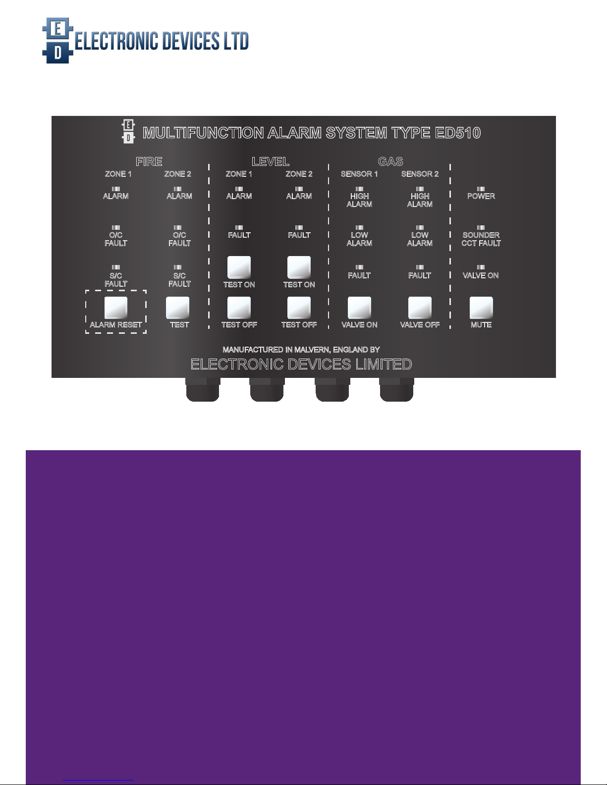
MANUFACTURED IN MALVERN, ENGLAND BY
ELECTRONIC DEVICES LIMITED
ALARM
FAULT
TEST ON
ALARM
O/C
FAULT
S/C
FAULT
ALARM
O/C
FAULT
S/C
FAULT
TEST OFFTESTALARM RESET
ALARM
FAULT
TEST ON
TEST OFF
HIGH
ALARM
LOW
ALARM
FAULT
VALVE ON
HIGH
ALARM
LOW
ALARM
FAULT
VALVE OFF
POWER
SOUNDER
CCT FAULT
VALVE ON
MUTE
MULTIFUNCTION ALARM SYSTEM TYPE ED510
FIRE LEVEL GAS
ZONE 1 ZONE 2 ZONE 1 ZONE 2 SENSOR 1 SENSOR 2

ED510 - GAS DETECTOR ED510 IM REV 2 - 23.08.2017
2
INDEX
FIRE DETECTION OPERATION 4
WATER LEVEL OPERATION 4
GAS DETECTION 4
FAULT CONDITION 4
FIRE EQUIPMENT 9
WATER LEVEL EQUIPMENT 10
EDP CALIBRATION PROCEEDURE 11
EDN CALIBRATION PROCEEDURE 12
GENERAL & FEATURES 3
PAGE
INSTALLATION 5
USER OPERATION 4
TEST PROCEEDURE & SETUP 9
PRINTED CIRCUIT BOAD LAYOUT 13
CUTOUT TEMPLATE 14
CONTROL PANEL 5
FIRE DETECTION 5
CHOOSING THE CORRECT DETECTORS 5
WIRING TYPICAL DETECTORS 6
WATER LEVEL DETECTION 7
AUTOMATIC BILGE PUMPING 7
WIRING TYPICAL FLOAT SWITCHES 7
GAS DETECTION 8
EDP SEMICONDUCTOR GAS SENSORS 8
AUDIABLE AND VISUAL ALARMS 8
CONNECTING A SOLENOID VALVE 9

ED510- GAS DETECTOR ED510 IM REV 2 - 23.08.2017
3
IMPORTANT: THE EQUIPMENT MUST NOT BE MODIFIED IN ANY WAY AND MUST BE INSTALLED AND SERVICED BY
COMPETENT PERSONNEL ONLY. IF IN DOUBT CONSULT ELECTRONIC DEVICES LTD (01684) 891500
GENERAL
The ED510 is a xed installation re, gas and level detection system operating from a nominal 12 or 24VDC supply depending
upon model.
FEATURES
• Two re detection zones fault monitored
• Two water level detection zones fault monitored
• Two gas detection sensor inputs fault monitored
• Two bilge pump outputs with manual override
• Automatic gas solenoid valve shut off
• Semiconductor,Catalytic or Electrochemical gas sensors may be tted.
• Sounder / beacon output fault monitored
• Integral alarm / fault buzzer
• Alarm relay output
• Splash proof front panel

ED510 - GAS DETECTOR ED510 IM REV 2 - 23.08.2017
4
USEr OPERATION
FIRE DETECTION OPERATION
In the event of a re being detected the appropriate zone alarm LED will illuminate and the internal buzzer will operate. If external
sounders and or beacons are tted they too will operate. If connected, the gas solenoid valve will close.
Pressing the MUTE button will turn off the sounders and beacons, including the internal buzzer. However the zone light will remain
on until the smoke, heat etc. has cleared and the RESET button is pressed. If the RESET button is pressed whilst a detector is
still in the presence of sufcient smoke, heat etc. the zone will re-trigger and the sounders and beacons will re-activate. Also if
the other re zone or a gas or bilge alarm occurs the sounders and beacons will re-alarm.
If it is needed to re-trigger the sounders for evacuation, rst press RESET then press the TEST button. The TEST button will put
re zone 1 in to alarm and hence operate the sounders.
Once all conditions have been cleared and RESET the gas solenoid valve can be operated by pressing the VALVE ON button. It
is important to check all pilot lights on the gas appliance and ensure they are ignited where necessary. The ED510 has a general
alarm output relay which can be used for various purposes including the shutdown of air conditioning, HVAC etc.. Any items
connected to these contacts should be checked for correct operation.
WATER LEVEL OPERATION
In the event of bilge water being detected the appropriate level zone alarm LED will illuminate and the internal buzzer will
operate. If external sounders and or beacons are tted they too will operate. If bilge pumps are connected they will be activated
to pump out any water.
Pressing the MUTE button will turn off the sounders and beacons, including the internal buzzer. However the zone light will
remain on until the oat switch has deactivated and the RESET button is pressed. Also if the other re zone or a gas or bilge
alarm occurs the sounders and beacons will re-alarm.
If you need to manually activate the bilge pumps this can be achieved by pressing the appropriate level zone TEST button. To
manually turn off pumps press the TEST OFF button. There is an ON DELAY which determines time to activate the pumps and
also RUN ON time which determines how longs after the pump should run which is set using the potentiometers on the underside
of the top PCB board. (See page 10 for adjustment settings)
GAS DETECTION OPERATION
In the event of a gas being detected the appropriate zone alarm LED will illuminate and the internal buzzer will operate. If external
sounders and or beacons are tted they too will operate. If connected, the gas solenoid valve will close.
Pressing the MUTE button will turn off the sounders and beacons, including the internal buzzer. However the zone light will
remain on until the gas sensor has cleared and the RESET button is pressed. Also if the other re zone or a gas or bilge alarm
occurs the sounders and beacons will re-alarm.
Once all conditions have been cleared and RESET the gas solenoid valve can be operated by pressing the VALVE ON button. It
is important to check all pilot lights on the gas appliance and ensure they are ignited where necessary. The ED510 has a general
alarm output relay which can be used for various purposes including the shutdown of air conditioning, HVAC etc.. Any items
connected to these contacts should be checked for correct operation.
FAULT CONDITION
In the event of faulty wiring of peripherals the appropriate zone fault LED will illuminate. Action will need to be taken to nd the
cause of any fault condition and ensure continued functionality of the ED510.

ED510- GAS DETECTOR ED510 IM REV 2 - 23.08.2017
5
INSTALLATION
CONTROL PANEL
The unit should be mounted in a convenient position for the operator away from possible mechanical damage. Remove the
enclosure and use it to mark out the mounting holes and cut out on to the bulkhead. Mount the control panel on to the bulkhead
temporarily using the M3 nuts and bolts provided. Once the electrical installation is completed, remove the nuts and screw the M3
bolts directly in to the captive nuts mounted on the enclosure. The control unit has a 3.15A fuse tted as standard. The current,
drawn from the vessels power supply, will depend upon peripheral items connected. The control unit and sensors typically draw
no more than 400mA in worst case. When including gas valves, sounders, beacons etc. the overall current consumption will
increase and therefore power supply cables, circuit breakers and fuses should be rated accordingly.
With integral batteries and charger the mains driven TYPE 3 power supply provides a battery backed 24VDC supply. Cable entry
must be made through the cable glands supplied. The enclosure has 12 x 20mm holes and the cable glands, should be mounted
in the most suitable positions. The unused holes should have the 20mm blind grommets (supplied) tted.
FIRE DETECTION
Fire detection circuits should be wired using cable approved for re detection installation such as FIRETUF or FP200. Note that
cable screens, if used, should only be earthed at one end.
It is good practice to always make the rst device on a re detection zone a call point, enabling manual operation of the alarms
when early signs of re are spotted before any detector has operated. Additionally making a call point the rst item on a zone
reduces the risk of it being out of circuit due to head removal or wiring faults.
CHOOSING THE CORRECT DETECTORS
The types of detector required varies for each location. Guidance should be sought from classication societies and SOLAS
regulations.
For general use, two types of smoke detector are recognised by standards as good, general-purpose re detectors offering a
high level of protection.
1. Ionisation smoke detectors have a high sensitivity to res that produce small smoke particles ie fast-burning, ame res that
can burn for some time without generating much smoke. (NO LONGER MARINE APPROVED)
2. Optical smoke detectors are particularly well suited to detecting slowburning, smouldering res which produce smoke with
large particles. They are widely used for protection in areas such as accommodation, escape corridors and electrical rooms, as
well as for general purposes.
Heat detectors offer protection in areas such as galleys and engine rooms where the environment is dirty or smoky under normal
conditions or where there is a high presence of airborne particles such as water vapour or exhaust fumes. However, it must be
recognised that any heat detector will respond only when a re is well-established and generating a high heat output. Therefore,
especially for vessels with large engine rooms, ame or smoke detectors should be considered.
Two types of heat detectors are available:
1. Rate-of-rise heat detectors are designed to sense a rapid increase in the temperature and are useful in environments where
the ambient temperature is normal, such as small occasionally used galleys, workshops and stores.
2. Fixed temperature heat detectors will signal an alarm once the temperature exceeds a pre-dened level and are effective
in environments with uctuating temperatures (such as boiler rooms) or where the ambient temperature is unusually high (for
example in an engine room).
 Loading...