

Electronic Broadcast Equipment SIRIO 2000T User And Maintenance Manual
Pag. 1
SIRIO 2000TSIRIO 2000T
SIRIO 2000TSIRIO 2000T
SIRIO 2000T
Electronic Broadcast Equipment
Rev. 2.0 - 06/03
- SIRIO 2000T -- SIRIO 2000T -
- SIRIO 2000T -- SIRIO 2000T -
- SIRIO 2000T -
2000 2000
2000 2000
2000
W FM POW FM PO
W FM POW FM PO
W FM PO
WER WER
WER WER
WER
TRANSMITTERTRANSMITTER
TRANSMITTERTRANSMITTER
TRANSMITTER
USER USER
USER USER
USER
AND MAINTENANCE MANUAND MAINTENANCE MANU
AND MAINTENANCE MANUAND MAINTENANCE MANU
AND MAINTENANCE MANU
ALAL
ALAL
AL
Pag. 2
SIRIO 2000TSIRIO 2000T
SIRIO 2000TSIRIO 2000T
SIRIO 2000T
Electronic Broadcast Equipment
The following have contributed to the production of this document:
Design, Layout, Schematics and Drawings: Roberto Paganelli
Thechnical and operational explanations: Maurizio Panicara
Shipping Instruction
Factory Service and Repairs
La garanzia è di 2 anni data fattura franco fabbrica. La garanzia non copre
i guasti dovuti a negligenza, dovuti a cause naturali e i materiali soggetti ad
usura nonche' la mano d'opera ed il trasporto. La garanzia decade in caso di
manomissione dell'apparato.
AEV è molto interessata ai Vostri commenti sui prodotti. I Vostri suggerimenti
ci saranno utili per la realizzazione di nuove apparecchiature e dei manuali,
questo sarà di grande utilità anche per Voi! Se lo desiderate potete inviarci
qualsiasi tipo di informazione sui prodotti e noi saremo ben lieti di leggerle.
Le informazioni possono essere inviate tramite E-mail all' indirizzo:
service@aev.net, o per posta all'AEV SERVICE.
Se avete la necessità di avere spiegazioni tecniche, contattate l'AEV
SERVICE e preparateVi per essere chiari nella descrizione del Vostro problema.
Scrivetevi il numero di matricola del Vostro apparato che potete trovare sulla
targhetta AEV attaccata al dispositivo, in quanto questa è la prima informazione
che dovete fornire.
Telefono: 39+051+6634711 Fax: 39+051+6634700
In caso di problemi che dovessero insorgere all'installazione dell'apparato, vi
raccomandiamo di verificare attentamente le spiegazioni contenute in questo
manuale e la corretta installazione. Se non siete ancora in grado di risolvere il
problema, contattate il supporto tecnico AEV SERVICE, per avere chiarimenti.
Se il problema è semplice può essere sufficiente una spiegazione telefonica. In
caso di spedizione all'AEV dell'apparecchio, per riparazione o manutenzione,
lo stesso può essere accettato dal SERVICE AEV solo dopo che Vi è stato
comunicato il numero di autorizzazione al rientro RMA. Questo numero deve
essere inserito nella documentazione di spedizione. Vi raccomandiamo inoltre
di allegare all'apparato una spiegazione dettagliata del difetto riscontrato o
del tipo di manutenzione richiesta ed eventualmente il nome della persona con
cui si è parlato all'AEV SERVICE. AEV non accetterà materiale in riparazione
con oneri di trasporto a proprio carico, in questo caso il materiale sarà
rifiutato.
In caso di spedizione dell'apparecchiatura all'AEV, utilizzate esclusivamente
l'imballo originale poichè solo in questo caso avrete la certezza che
l'apparecchiatura non subirà shock nel trasporto. Se non avete conservato
l'imballo originale vi consigliamo di richiedercene un'altro.Se volete spedirci
l'apparato con un imballo diverso, abbiate cura di effettuare un doppio
imballo, tra i due interponete del materiale morbido, questo serve ad assorbire
i colpi che vengono ricevuti durante il trasporto.
Riportate sul pacco in rosso la parola: FRAGILE.Ricordate che il numero
RMA deve essere visibile anche sul pacco, in caso contrario non verrà
accettato.
Copyright AEV S.p.A '96-'03. Tutti i diritti riservati. Nessuna parte di questa
pubblicazione puó essere riprodotta, trasmessa, archiviata in un sistema di
riferimento o tradotta in altre lingue in qualsiasi forma con qualsiasi mezzo,
senza il consenso scritto di AEV S.p.A.
Registrazione, Garanzia, Registration, Guarantee, Feedbak
Feedback
Technical Support
The equipment is warranted for a period of 2 years from the date of invoice
(ex-works). The warranty does not cover faults provoked by carelessness,
natural causes and parts subject to wear. In addition, the cost of labour and
shipment is not covered. The warranty will be voided if the equipment is
mishandled.
AEV welcomes your comments on our products. Your suggestions may
be extremely useful to develop new equipment and manuals and this will be of
benefit to you too! Let us have your comments on our products and we will
be pleased to read them.
Send your information by e-mail to the following address: service@aev.net, or
send a letter to the AEV SERVICE Department.
If you require technical support, contact AEV SERVICE giving a clear
and concise account of your specific problem. Quote the serial number of your
equipment by referring to the AEV nameplate attached to the equipment itself
as this is the most important piece of information to be provided.
Telephone: 39+051+6634711 Fax: 39+051+6634700
If problems arise while the equipment is being installed, consult this manual
and check that the installation is being carried out properly. If the problems
still cannot be solved, call the AEV SERVICE Department for further
information. If the problem is a minor one we can a telephone call will
probably suffice. If, on the other hand, the equipment is to be shipped to AEV
for service or repairs, the AEV SERVICE Dept. will accept it only if the RMA
return authorisation number has been provided. This number must be included
in the shipping documents. We also recommend providing a detailed
description of the fault which has occurred, the type of service needed and (if
required) the name of the employee at the AEV SERVICE Dept. you have
spoken to. No repairs will be made if the cost of shipment is charged to AEV.
In this case, we will not accept the delivery.
When shipping the equipment to AEV, use the original package in order
to be certain that it will be fully protected during handling. If you need the
original package, call us for a new one. If you ship the equipment in a
different packing container, take care to provide a double package by
interposing padding material between the two containers in order to fully
protect the equipment during shipment. The package should be marked
"FRAGILE" in red.
Remember that the RMA number must be clearly visible on the package. If it is
not, the equipment will not be accepted.
Copyright AEV S.p.A. '96-'03. All rights reserved. No part of this publication
may be reproduced, trasmitted, archived in a reference system or translated into
other languages in any form or by any means without the written consent of
AEV S.p.A.
Pag. 3
SIRIO 2000TSIRIO 2000T
SIRIO 2000TSIRIO 2000T
SIRIO 2000T
Electronic Broadcast Equipment
AVVERTENZE
ATTENZIONE, leggere attentamente le avvertenze contenute nel seguente paragrafo in
quanto forniscono importanti indicazioni riguardanti la sicurezza, l'installazione, l'uso e
la manutenzione dell'apparato.
Il non adempimento delle norme o degli avvertimenti specifici riportati in questo manuale
vìola le norme di sicurezza di disegno, costruzione e uso di questo apparato.
AEV S.p.A. declina ogni responsabilità nel caso non venga rispettata anche solo una
parte delle seguenti prescrizioni.
AEV S.p.A. declina ogni responsabilità nel caso l'utilizzatore finale rivenda il prodotto.
L'impiego è rivolto a personale in grado di potere utilizzare questo apparato e si
presuppone che lo stesso sia conoscenza delle seguenti prescrizioni.
• Conservare con cura questo manuale per ogni ulteriore consultazione, esso deve
essere custodito nelle vicinanze dell'apparato stesso e di facile rintracciabilità.
• Dopo aver tolto l'imballo assicurarsi dell'integrità dell'apparato.
• Evitare shock meccanici che possano danneggiare l'apparato.
• Gli elementi dell'imballo (sacchetti di plastica, polistirolo, chiodi, ecc.) non devono
essere lasciati alla portata dei bambini in quanto potenziali fonti di pericolo.
• Evitare di utilizzare l'apparecchiatura in luoghi dove sia presente una temperatura non
compresa nell'intervallo ammesso dalle caratteristiche tecniche dichiarate.
• Prima di collegare l'apparato accertarsi che i dati di targa siano rispondenti a quelli
della rete di distribuzione elettrica (la targa è posta sul contenitore dell'apparato).
• Non rimuovere per alcun motivo la targhetta adesiva applicata sull'apparecchio
contenente i dati essenziali di macchina e la matricola.
• Per il collegamento alla rete di alimentazione utilizzare esclusivamente il cavo di rete
venduto insieme all'apparato.
• Questo apparato dovrà essere destinato all'uso per il quale è stato espressamente
concepito.
• Ogni altro uso dell'apparato è da considerarsi improprio e quindi potenzialmente
pericoloso a persone, animali o cose. Il costruttore non può essere considerato
responsabile per eventuali danni derivanti da usi impropri, erronei ed irragionevoli.
• L'uso di qualsiasi apparato elettrico comporta l'osservanza di alcune regole
fondamentali. In particolare:
- Non toccare l'apparato con parti del corpo bagnate e/o umide. L'apparato non deve essere esposto a stillicidio e/o spruzzi d'acqua. Non usare l'apparato nelle vicinanze di fonti di calore intenso ed in presenza di materiali
esplosivi.
-
Non tentare di introdurre alcun oggetto estraneo all'interno dell'apparato.
-
Non permettere che l'apparato sia usato da bambini e/o da personale impreparato.
• Prima di effettuare qualsiasi operazione di pulizia e/o manutenzione esterna, disinserite
l'apparato dalla rete di alimentazione elettrica ed attendere almeno 2 secondi come
prescritto dalle normative che regolamentano la sicurezza.
SAFETY PRECAUTIONS
IMPORTANT: Carefully read this paragraph as it contains important instructions
concerning operator safety and directions regarding the installation, operation and
maintenance of the equipment.
Failure to observe the safety instructions and information given in this manual
constitutes an infringement of the safety rules and design specifications
provided for this piece of equipment.
AEV S.p.A. declines all responsibility if any one of the safety rules given herein is not
observed.
AEV S.p.A. declines all responsibility if the end-user resells the product.
The equipment is to be used by people capable of operating it in a trouble-free manner
and it is assumed that they are aware of the following safety rules.
• Keep this manual with the utmost care and close at hand so that it can be consulted
whenever needed
• After unpacking the equipment, check it for condition.
• Avoid banging the equipment.
• The packing material (plastic bags, polystyrene, nails, etc.) must never be left within
the reach of the children, as these items are potential sources of danger.
• Do not use the equipment in places where the temperature is not within the
recommended range, as specified by the manufacturer.
• Before connecting the equipment, make sure the nameplate specifications correspond
to the mains electricity supply (the nameplate is located on the equipment enclosure).
• Do not remove the sticker from the equipment as it contains important specifications
and the relevant serial number.
• To join the equipment to the mains supply, use the power cord purchased with the
equipment.
• The equipment must be used only for the purpose it was designed for.
• Abuse or misuse of the equipment is extremely dangerous for people, pets and
property. The manufacturer declines all responsibility for damage and injury resulting from
improper use and mishandling.
• Certain basic safety rules must be observed when using electrical equipment, in
particular:
-
Never touch the equipment with wet and/or damp hands or other parts of the body.
- Keep the equipment away from drops of water or sprinkling systems.
-
Never use the equipment near high heat sources or explosive material.
-
Do not introduce any extraneous matter into the equipment.
- Do not allow children or untrained people to use the equipment.
• Before cleaning or servicing the equipment outside, disconnect it from the supply and
wait at least 2 seconds before working on it, as recommended by current safety regulations.
• In the event of faults and/or improper operation, turn off the equipment, shut off the
electrical power and call your dealer.

Pag. 4
SIRIO 2000TSIRIO 2000T
SIRIO 2000TSIRIO 2000T
SIRIO 2000T
Electronic Broadcast Equipment
• In caso di guasto e/o di anomalo funzionamento dell'apparato è obbligo spegnerlo,
disconnettere l'alimentazione, non manometterlo e rivolgersi al rivenditore.
• Non tentare di fare alcun tipo di riparazione e/o regolazione che preveda la rimozione
di coperchi o l'estrazione di schede.
• La rottura del fusibile interno all'alimentatore è sintomo di un guasto generale
dell'alimentatore stesso; la sua sostituzione non è consentita se non da personale
specializzato e autorizzato. Si consiglia di rivolgersi direttamente al rivenditore.
• Per eventuali riparazioni rivolgersi direttamente al rivenditore e richiedere che vengano utilizzati
ricambi originali. Il mancato rispetto di quanto sopra può compromettere la sicurezza
dell'apparato.
• L'apparato deve essere collegato alla rete di alimentazione munita di linea di terra
regolamentare ed efficiente.
• L'esecuzione dell'impianto elettrico deve essere conforme alle norme C.E.I. 64-8 "Norme
degli impianti elettrici negli edifici civili".
• In fase di installazione è tassativo prevedere uno spazio libero intorno all'apparecchio
di almeno 1 cm per garantire un adeguata areazione.
N.B. L'apparato è costruito a regola d'arte. L'affidabilità elettrica e meccanica
sarà mantenuta efficiente se verrà fatto un uso corretto dell'apparato e rispettate
le prescrizioni di manutenzione ove previste.
• Do not attempt to make repairs and/or adjustments when covers/guards or circuit boards
are to be removed.
• Blown fuses inside the power supply indicate that there may be a fault in the power
supply itself. The fuses must be replaced by qualified and authorised persons. It is
advisable to call your nearest dealer.
• Call your dealer for any repairs and be certain original spare parts are used. Failure
to observe this rule may adversely affect the safety level of your equipment.
• The equipment is to be connected to the mains supply and provided with adequate and
efficient earth conductors.
• The electrical wiring must be done in compliance with current electrical codes CEI 648 “Electrical specification for domestic buildings”.
• When installing, leave a clearance of at least 1 cm around the equipment to allow air to
pass freely.
NOTE. This piece of equipment has been manufactured to the highest standards
of workmanship. It must be used properly and serviced as recommended to
ensure long-term dependable operation.
Pag. 5
SIRIO 2000TSIRIO 2000T
SIRIO 2000TSIRIO 2000T
SIRIO 2000T
Electronic Broadcast Equipment
SICHERHEITSINWEISE
ACHTUNG! Die im folgenden Abschnitt beshriebenen Hinweise mit Sorgfalt lesen, da
sie wichtige Informationen über die Sicherheit, die Installation, die Bedienung und die
Wartung enthalten.
Die Nichterfüllung der Vorschriften oder der spezifischen Warnungen, die in diesem
Handbuch enthalten sind, verletzt die Zeichnungs-, Herstellungs- und
Bedienungssicherheitsnormen dieses Gerätes. AEV S.p.A. lehnt jegliche Verantwortung
ab, auch wenn nur ein Teil der folgenden Vorschriften nicht erfüllt wird.
Nur Fachpersonal kann das Gerät benutzen und es wird vorausgesetzt, daß das
zuständige Personal von diesen Vorschriften Kenntnis hat.
• Das vorliegende Handbuch soll für ein evtl. künftiges Nachschlagen mit Sorgfalt
aufbewahrt werden; es soll sich in der Nähe des Gerätes befinden und soll leicht
auffindbar sein.
• Nach der Entfernung der Verpackung, die Vollständigkeit des Gerätes prüfen. Falls
einige Zweifel bestehen, verwenden Sie das Gerätes prüfen. Falls einige Zweifel
bestehen, verwenden Sie das Gerät nicht und wenden Sie sich an den Händler.
• Mechanische Schocks vermeiden, die das Gerät beschädigen könnten.
• Das Verpackungsmaterial (Plastiktüte, Polystirol, Nägel, u.s.w.) soll nicht in der
Reichweite von Kindern verlassen werden, da es eine potentielle Gefahrquelle darstellt.
• Das Gerät soll nicht in Umgebungen verwendet werden, wo die Temperatur nicht
innerhalb des Bereichs liegt, der gemäß den angegebenen technischen Merkmalen
zugelassen ist.
• Vor dem Anschluß des gerätes prüfen ob die Schilddaten den Daten der elektrischen
Versorgung entsprechen (das Schild ist auf dem Gerätegehäuse angebracht).
• Das Klebschild auf dem Gerät, das die wichtigsten Daten der Maschine und die Seriennr. zeigt, soll nie entfernt werden.
• Für den Anschluß an das Versorgungsnetz kann nur das mitgelieferte Kabel verwendet
werden.
• Das vorliegende Gerät kann nur für die Benutzung verwendet werde, für die das Gerät
ausdrücklich ausgelegt wurde.
• Jegliche andere Benutzung ist als unsachgemäss zu verstehen und deshalb ist für
Personen, Tiere oder Gegenstände potentiell gefährlich.
• Die Verwendung eines elektrischen Gerätes sieht die Einhaltung einiger Grundnormen
vor, wie:
- Das Gerät nicht mit feuchten oder naßen Händen oder Wasserspritzen ausgesetzt
werden
Das Gerät soll nicht in der Nähe von Wärmequellen und wo Explosivstoffe vorhanden
sind, verwendet werden Kein fremder Gegenstand in das Gerät einsetzen
Das Gerät soll nicht von Kindern und/oder unfähiges ohne Überwachung verwendet
werden.
• Vor Reinigungs- und/oder Wartungsarbeiten soll das Gerät von der elektrischen
Versorgung durch die Entfernung des Versorgungskabels ausgeschaltet werden und
soll man 2 sek. abwarten, wie von den Sicherheitsnormen vorgeschrieben.
• Falls eine Störung oder eine Fehlfunktion des Gerätes vorhanden sind, sollen das Gerät
und das Versorgungskabel vom Netz ausgeshaltet und keinen Eingriff an das Gerät
durchgeführt werden.
PRECAUTIONS
ATTENTION, lire toutes les instructions donnè es dans ce paragraphe car elles
concernent la securitè, l'installation, l'emploi et l'entretien.
Ne pas accomplir les régles et les prècautions spécifiques données dans ce manuel est
une violation des règles de sécurité de dessin, de construction et d'emplol de cet
appareil.
AEV S.p.A. décline toute responsabilité si on ne suit pas même seulement une partie de
ces précautions.
AEV S.p.A. décline toute responsabilité si l'utilisateur final revend le produit.
L'emploi s'adresse à un personnel qui est en mesure d'utiliser cet appareil et qui
connaît les précautions suivantes.
• Garder soigneusement ce manuel pour toute autre consultation. Il doit être gardé près
de l'appareil ou dans un lieu où on peut le trouver avec facilité.
• Après avoir enlevé l'emballage il faut s'assurer de l'intégrité de l'appareil. Si on a
quelques doutes ne pas utiliser l'appareil et s'adresser au détaillant.
• Eviter des shocks mécaniques qui peuvent endommager l'appareil.
• Les élèments de l'emballage (les sachets de plastique, le polystyrolène, les clous, etc.
) ne doivent pas être laissés à la portée des enfants car ils peuvent être un danger pour
eux.
• Eviter l'utilisation de l'appareil dans des lieux où il n'y a pas une tempera ture qui est
dans l'intervalle admis par les caractéristiques techniques déclarées.
• Avant de connecter l'appareil vérifier que les données de la plaque correspondent à
celles du réseau de distribution électrique (la plaque est située sur le conteneur de
l'appareil).
• Ne jamais enlever (pour n'importe quelle raison) la plaque adhésive qui se trouve sur
l'appareil et qui contient les données essentielles de la machine et la matricule.
• Pour la connexion au réseau d'alimentation utiliser seulement le câble de réseau qui
est vendu avec l'appareil.
• Cet appareil devra être utilisé seulement pour l'usage dont il a été conçu.
• Tout autre usage doit être considéré impropre et donc potentiellement dangereux pour
les personnes, les animaux et les choses. Le constructeur n'est pas responsable pour
les dommages qui dérivent des usages impropres, erronés et irraisonnés.
• L'usage d'un appareil électrique prévoit l'observation de quelques règles
fondamentales.En particulier:
- Ne pas toucher l'appareil avec vos parties du corps ouillées et / ou humides. -
L'appareil ne doit pas être exposé à stillation et /ou aux jets d'eau.
- Ne pas utiliser l'appareil près des sources d'une forte chaleur et en présence d'explosifs.
Ne pas chercher à introduire des objects étrangers dans l'appareil. Ne pas permettre que l'appareil soit utilisé par des enfants et / ou par des incapables sans
surveillance.
• Avant de faire n'importe quelle opération de nettoyage et / ou d'entretien, débrayer
l'appareil du réseau d'alimentation électrique en enlevant le cordon de réseau et attendre
au moins 2 secondes, en suivant ainsi les normes qui régularisent la sécurité.
Pag. 6
SIRIO 2000TSIRIO 2000T
SIRIO 2000TSIRIO 2000T
SIRIO 2000T
Electronic Broadcast Equipment
• Keine Instandsetzungs- und/oder Einstellungsarbeit durchführen, die die Entfernung von
Deckeln oder das Herausziehen von Karten vorsehen.
• Das Brechen der Sicherung innerhalb des Netzteils ist ein Zeichen einer generellen
Störung des Netzteils; das Netzteil kann nur von autorisiertem Personal ersetzt werden.
Wir empfehlen, sich an den Händler zu wenden.
• Für eine evtl. Instandsetzung von Original-Ersatzteilen forden. Die Nichteinhaltung der
o.g. Empfehlung könnte die Sicherheit des Gerätes beeinträchtigen.
• Das Gerät soll an das Versorgungsnetz angeschlossen werden, die mit
ordnungsgemässer und wirksamer Erdung ausgestatten werden soll.
• Die Ausführung der elektrischen Anlange soll den CEI Normen 64-8 "Normen der
elektrischen Anlagen für Zivilgebäuden" entsprechen.
• Während der Installation ist es ausdrücklich, einen freien Raum von 1 cm um das Gerät
vorzusehen, um eine ordnungsgemässe Belüftung gewährzuleisten.
N.B.: Das Gerät is fachgerecht hergestellt. Die elektrische und mechanische
Zuverlässigkeit wird erhalten, wenn das Gerät ordnungsgemäss benutzt wird und
wenn die Wartungsvorschriften, falls vorgesehen, beobachtet werden.
• Si on a une panne et / ou un mauvais fonctionnement de l'appareil, il faut l'éteindre,
deconnecter l'alimentation, ne pas l'endommager et s'adresser au détaillant.
• Ne pas chercher à faire une réparation et / ou une mise à point qui rend nécessaire le
déplacement des couvercles ou l'extraction des fiches.
• La rupture du fusible dans l'alimentation signifie qu'il y a une panne de l'alimentation
même; son remplacement doit être fait seulement par le personnel autorisé. On conseille
de s'adresser directement au détaillant.
• Pour une réparation s'adresser au détaillant et exiger l'utulisation des pièces de
rechange originales. Ne pas respecter ces normes peut compromettre la sécurité de
l'appareil.
• L'appareil doit être connecté au réseau d'alimentation qui a une ligne de terre
réglementaire et fonctionnante.
• L'exécution de l'installation électrique devra être conforme à la norme C.E.I 64-8
"Normes des installations électriques dans les édifices civils".
• Quand on installe l'appareil on doit prévoir une espace libre autour de lui d'à peu près 1
cm pour garantir une bonne aération.
N.B. L'appareil a été construit dans les règles de l'art. La fiabilité électrique et
mécanique sera toujours efficace si on utilise correctement l'appareil et si on
respecte les prescriptions d'entretien.

Pag. 7
SIRIO 2000TSIRIO 2000T
SIRIO 2000TSIRIO 2000T
SIRIO 2000T
Electronic Broadcast Equipment
WARNING!
The currents and voltages in this equipment are dangerous!
Personnel must at all times observe safety regulation!
This manual is intended as a general guide for trained and qualified personnel who are aware of the dangers inherent in handling
potentially hazardous electrical and electronic circuits.
It is not intended to contain a complete statement of all safety precautions which should be observed by personnel in using this
or other electronic equipment.
The installation, operation, maintenance and service of this equipment involves risks both to personnel and equipment. and must
be performed only by qualified personnel exercising due care.
AEV S.pA.
shall not be responsible for injury or damage resulting from improper procedures or from the use of improperly trained
or inexperienced personnel performing such tasks.
During installation and operation of this equipment, local building codes and fire protection standards must be observed.
WARNING!
Always disconnect power before opening covers, doors, enclosures, gates, panels or shields.
Always use grounding sticks and short out high voltage points before servicing.
Never make internal adjustments, perform maintenance or service when alone or when fatigued.
Do not remove, short~circuit or tamper with interlock switches on access covers, doors, enclosures, gates. panels or
shields.
Keep away from live circuits, know your equipment and don’t take chances.
WARNING!
In case of emergency ensure that power has been disconnected
Pag. 8
SIRIO 2000TSIRIO 2000T
SIRIO 2000TSIRIO 2000T
SIRIO 2000T
Electronic Broadcast Equipment
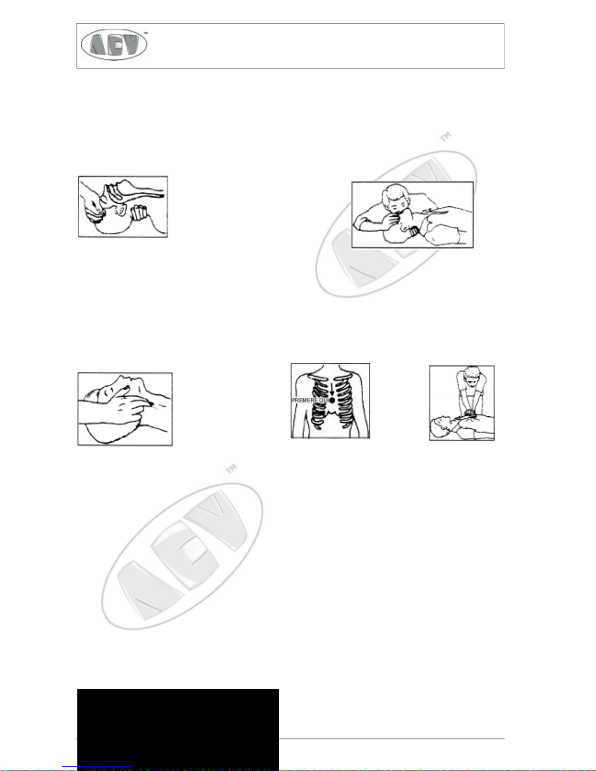
Treatment of electrical Shock
1, If victim is not responsive follow the A-B-C’S of basic life support.
PLACE VICTIM FLAT ON HIS BACK ON A HARD SURFACE
A AIRWAY B BREATHING
IF UNCONSCIOUS, IF NOT BREATHING,
OPEN AIRWAY BEGIN ARTIFICIAL
BREATHING
LIFT UP NECK, TILT HEAD,PINCH NOSTRILS
PUSH FOREHEAD SACKF MAKE AIRTIGHT SEAL,
CLEAR OUT MOUTH IF NECESSARY 4 QUICK FULL BREATHS
OBSERVE FOR BREATHING. REMEMBER MOUTH TO MOUTH.
RESUSCITATION MUST BE
COMMENCED AS SOON AS POSSIBLE
C CIRCULATION
CHECK CAROTID PULSE DEPRESS STERNUM 1 1/2" to 2"
IF PULSE ABSENT APPROX. 80 SEC. : ONE RESCUE 15 COMPRESSION
BEGIN ARTIFICIAL 2 QUICK BREATHS.
CIRCULATION APPROX. 60 SEC. : TWO RESCUERSO 5 COMPRESSIONS I BREATH
NOTE: DO NOT INTERRUPT RHYTHM OF COMPRESSIONS
WHEN SECOND PERSON IS GIVING BREATH.
Call for medical assistance as soon as possible
2) If victim is responsive.
a. Keep them warm.
b. Keep them as quiet as possible,
c. Loosen their clothing (a reclining position is recommended).

Pag. 9
SIRIO 2000TSIRIO 2000T
SIRIO 2000TSIRIO 2000T
SIRIO 2000T
Electronic Broadcast Equipment
FIRST-AID
Personnel engaged in the installation, operation, maintenance or servicing of this equipment are urged to become
familiar with first-aid theory and practices, The following information is not intended to be a complete first-aid procedure, it is brief and is only to be used as a reference. it is the duty of all personnel using the equipment to be prepared
to give adequate Emergency First Aid and thereby prevent avoidable loss of life.
Treatment of electrical Burns
1) Extensive burned and broken skin.
a. Cover area with clean sheet or cloth. (Cleanest available cloth article).
b. Do not break blisters, remove tissue, remove adhered particles of clothing, or apply any salve o r
ointment.
c. Treat victim for shock as required.
d. Arrange transportation to a hospital as quickly as possible
e. If arms or legs are affected keep them elevated.
NOTE
If medical help will not be available within an hour and the victim is conscious and not vomiting, give him a weak solution of salt
and soda: 1 level teaspoonful of salt and 1/2 level teaspoonful of baking soda to each quart of water (neither hot or cold).
Allow victim to sip slowly about 4 ounces (half a glass) over a period of 15 minutes.
Discontinue fluid if vomiting occurs (Do not give alcohol).
2) Less severe burns - (1st & 2nd degree)
a. Apply cool (not ice cold) compresses using the cleanest available cloth article,
b. Do not break blisters, remove tissue, remove adhered particles of clothing, or apply salve or
ointment.
c, Apply clean dry dressing if necessary.
d. Treat victim for shock as required.
e. Arrange transportation to a hospital as quickly as possible.
f. If arms or legs are affected keep them elevated.

Pag. 10
SIRIO 2000TSIRIO 2000T
SIRIO 2000TSIRIO 2000T
SIRIO 2000T
Electronic Broadcast Equipment

Pag. 11
SIRIO 2000TSIRIO 2000T
SIRIO 2000TSIRIO 2000T
SIRIO 2000T
Electronic Broadcast Equipment
SIRIO 2000T
87.5 ÷ 108 MHz FM 2000W TRANSMITTER
1. INTRODUCTION
SIRIO 2000T series transmitters are the.result of a long experience gained by A.E.V. along years of
producing FM broadcast equipment, transmitters, stl and stereo encoders.
These transmitters are specifically designed to comply with the latest international standards and the
requirements of the most advanced broadcasters, meeting tighter specifications than usually required, but
still at an affordable cost.
This transmitter produces an Hi-Fi-quality modulated signal, with a low residual noise and distortion. RF
signal is free from spurious and harmonic components to an higher degree than required by CCIR, European,
USA and most other national standards.
To obtain such an outstanding performances is mandatory to rely on qualified personnel to design the
equipment, but also for the user to install and to verify the equipment layout of the radio station. I.e. the
transmitter, the link with the studio, the power amplifier, the antennas, the cables and the connectors.
Only following this kind of procedure will insure the best performances, likewise reliability and stability.
Transmitter must not be tampered with by unskilled personnel and our after-sale service is always
available to customers for any technical problem. Before proceeding to installation, please make sure to
carefully have read ALL PAGES of this manual and gained enough confidence with the equipment.
Our transmitters are very stable units, internal pre-settings or adjustments other than frequency and few
other options are normally not required. In case, any work must be carried out by skilled personnel, with
the proper instruments and documentation. Improper adjustments or tampering with the settings may harm
the transmitter and/or jeopardize the guaranteed performances.
THIS EQUIPMENT COMPLIES WITH ALL RELEVANT EMI/EMC AND SAFETY
REQUIREMENTS, ETSI EN300384, ETS300447 AND EN60215 STANDARDS.
NO INTERNAL ADJUSTMENT OR PRESETTING IS REQUIRED DURING NORMAL
OPERATIONS. THE TRANSMITTER SHALL BE PROPERLY EARTHED AND OPERATED
WITH ALL THE COVERS CLOSED TO PREVENT ELECTRICAL HAZARDS AND TO
COMPLY WITH EMC STANDARDS.
——— MAINS VOLTAGE MAY KILL ———

Pag. 12
SIRIO 2000TSIRIO 2000T
SIRIO 2000TSIRIO 2000T
SIRIO 2000T
Electronic Broadcast Equipment
2. GENERAL DESCRIPTION
SIRIO 2000T is a 2KW rated, direct-synthesis, high quality FM-modulated transmitter. Being digitally
controlled, it is extensively programmable by front panel, on field or remotely, in every respect: frequency,
power, channel sensitivity, preemphasis, functioning mode (mono, stereo, external mpx), clock, date and
many other parameters, without adjusting or replacing any part. A powerful 3-levels password system
allows an high degree of security and privacy as it may be required in different situations. The transmitter
requires little or no maintenance and its simple modular layout allows easy testing and servicing.
As required by a number of specifiical national standards, our transmitters incorporate a state of the art
low-pass audio filters on mono and stereo channels, and a sharp acting modulation limiter which is usually
set for a peak deviation of 75 kHz. Its use should never be avoided. If required a different deviation, this
can be obtained pre-setting. In any case the threshold shouldn't exceed a deviation higher than 150 kHz.
Output frequency is phase-locked to a temperature-compensated crystal oscillator, which insures
superior precision and stability. A very low noise, low distortion VCO produces an harmonics-free and
spurious-free signal. Each time the transmitter is turned on or the frequency is modified, a control circuit
inhibits the presence of output power until the transmitter is locked on the programmed frequency.
To lower the noise threshold, low-frequency inputs are fitted with balanced input circuitry. The input level
is precisely adjustable over a wide range by means of a 0.5dB step variable attenuator. The transmitter has
an auxiliary input, specifically designed for RDS and SCA encoders. A modulation output allows to control
other transmitters (or STLs) with the same internally processed high-quality mpx signal.
The alphanumeric display and the keyboard allow an easy and accurate metering, adjustment and
continuous monitoring of modulation levels, power, operation and other internal parameters. Such details
may be externally available on the same RS232 I/O port that may be used to remotely check or control the
transmitter. In addition to the serial I/O, some signals (RF power, On the air state, Disable line) are available
on a parallel I/O socket for easy interfacing with others analog controllers or supervisory systems.
A top-quality stereo encoder may be factory installed as an option. This even later in the field requiring
such an upgrade a minimum technical skill to be performed. The powerful internal software recognize the
encoder presence and automatically enables the related functions.
The RF power amplifier employs a broadband design and has plenty of reserve: the output power is
feedback controlled for increased stability to an higher level than the nominal . Allowed reflected power
is limited to conservative level to prevent output stage degradation; direct power is accordingly reduced not
to exceed the reflected power safety level. A sturdy telecom-grade high efficiency switch-mode power
supply allows operations even in unstable and noisy mains environment.
The temperature alarm circuitry reduces the output power in case of high room or esternal temperature
in order to remain anyway on the air, in spite of the adverse condition.
Pag. 13
SIRIO 2000TSIRIO 2000T
SIRIO 2000TSIRIO 2000T
SIRIO 2000T
Electronic Broadcast Equipment
3. TECHNICAL FEATURES
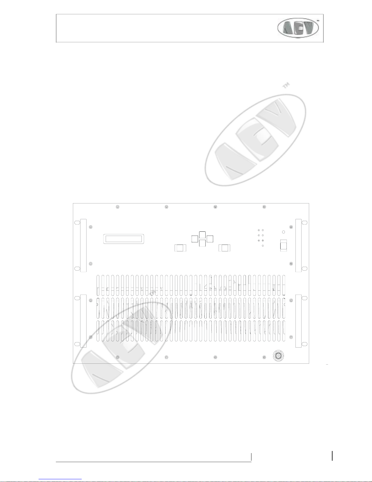
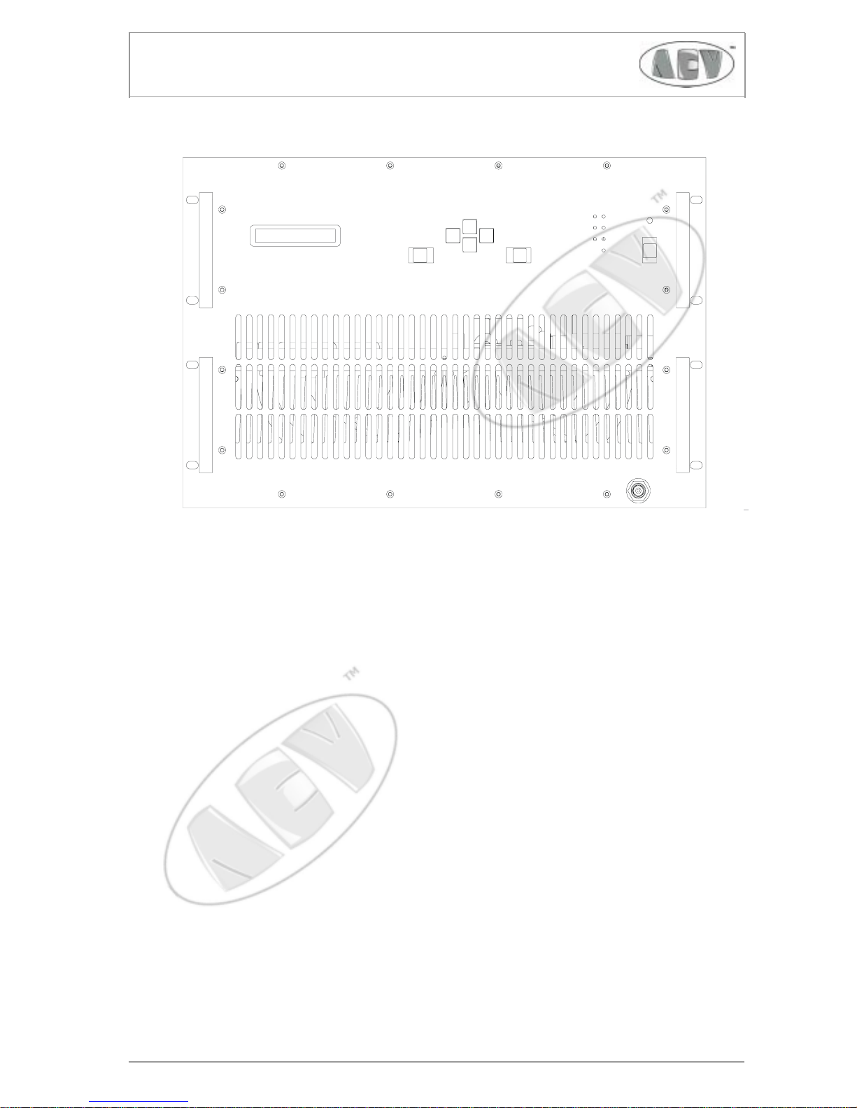
3.1 FRONT PANEL COMMANDS AND SIGNALLING
SIRIO 2000T front panel is simple and easy to control. The wide alphanumeric display and the control
keyboard are self-explanatory and allow the menu-driven navigation through the various options.
Great care was taken in the design of the software to give a natural approach to the various controls and
to allow operation and programming in every respect of the transmitter.
The password management, when used, hides some functions and prevents voluntary or involuntary
tampering with the most critical options and data by unauthorised people.
The ON/stand-by key does not power off the transmitter, which is still locked on frequency and ready
to transmit as soon as the key is pushed or a remote command is sent. Note that a mains failure won't change
the st-by/ON status, the transmitter will restart in the same state it was, when line power will be back
Some leds, visible at a glance, indicate proper functioning or warning states.
Pag. 14
SIRIO 2000TSIRIO 2000T
SIRIO 2000TSIRIO 2000T
SIRIO 2000T
Electronic Broadcast Equipment
IN CASE OF DUCTING OF T H E VENTILATI ON AIR ,
AN EXTERNAL EXTRA C TIN G FAN IS REQUIRED.
LEFT
AUDIO INPUT
RIGHT
REMOTE
2 Signal -
1 Ground
3 Signal +
231
20k-10 0k
MODULATION
MONITOR RS232AUX MPX
10-10000 0 H z
RF OUTPUT
50 OHM
MADE IN ITALY
0678
ABSOLUTELY REMOVE POWER CORD F ROM MAINS
GROUND
UPPER AND BOTTOM COVER S ARE REQ UIRED TO
ELECTRICAL SHOCKS, DO NOT REMOVE ANY PANEL.
MEET BOTH SAFETY AND EMI REQUIREMENTS.
CIRCUIT S AT THE REAR OF TH IS PANEL A RE
CONNECTED TO MAINS VOLTAGE. TO PREVENT
CAUTION!
POWER
ON
I PAN NE LLI DI C HIUSU RA SUPER IORE ED INFERI ORE
PRIMA DI CA M B IARE I FUSIBILI INTERNI, DISCONNE T T E R E
SONO RICHIESTI PER LA CONFORMITA' AGLI STANDARD
DI SICUREZZA E DI EMISSIONE ELETTROMAGNETICA.
ASSOLUTAMENTE IL COLLEGAMENTO ALLA RETE
NON RIMUOVERE LE COPERTURE. INOLTRE ENTRAMBI
RETE. PER EVITARE RISCHI DA SCOSSA ELETTRICA
SUL RETRO DI QUES TO PANNELLO SONO DIRET-
TAME NTE ACCESSIBILI CIR CUITI A TE NSION E DI
BEFORE REPLAC IN G INTERNA L F US ES.
ATTENZIO NE!
E' RICHIESTO UN GRUPPO DI ASPIRAZIONE ESTERNO.
IN CASO DI CONV OGLIAMENTO DEL L 'A RIA DI VENT IL AZIONE
4500VA (RFB2001)
230Vac 50/60Hz
2500VA (RFB1001)
OFF
0678
SISTEMI
ELETTRON ICI
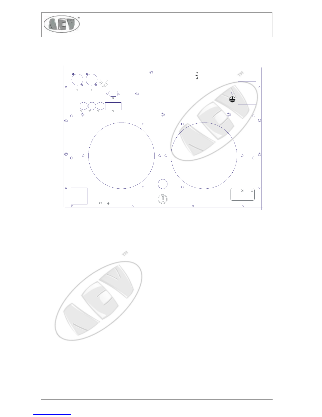
3.2 REAR PANEL CONNECTORS
All transmitter inputs and outputs are located on the back panel.
- The audio channels input sockets on balanced female XLR-type connectors
- The wide-band external processed / stereo or composite signal input on a grounded unbalanced
BNC connector
- The frequency limited (20k ÷ 100kHz) auxiliary channel input on a grounded, unbalanced BNC
connector
- The LF modulation output for monitoring, RDS external synchronisation or re-broadcasting
purpose, BNC-type
- The inverted wired RS232 DB9 female remote serial control port
- The remotr parallel control port, DB9 male type
- The RF antenna connector, N-type
- The hot centre-pin on the "EXTERNAL" BNC input is physically in parallel with the signal + input
(pin 3) on the mono/right channel XLR socket. For this reason both connectors cannot be used
at the same time.
On the left side of the panel it is located the mains power switch, the power cord and an earth screw
for system earthing in addition to the ground conductor on the cord. The power switch trips if an
overcurrent condition should occur.
Please note that the transmitter is usually factory pre-set for 220-240 Vac
nominal mains voltage. If required, 110-120 Vac range must be internally set
on the mains tranformer board.

Pag. 15
SIRIO 2000TSIRIO 2000T
SIRIO 2000TSIRIO 2000T
SIRIO 2000T
Electronic Broadcast Equipment
Note that:
- The hot centre pin of the "EXTERNAL" BNC input (MPX or stereo inout) is physically in parallel to
the "+ input" signal (pin 3) on the mono/right channel XLR socket. For this reason it's not possible to
use both inputs at the same time.
On the left side of the panel are located the mains power switch, the power cord and an earth screw for
a separated earthing system as well as the ground conductor on the cord. Should an over-current
condition take place, the power switch would trip and stop the device.

Pag. 16
SIRIO 2000TSIRIO 2000T
SIRIO 2000TSIRIO 2000T
SIRIO 2000T
Electronic Broadcast Equipment
4. TECHNICAL SPECIFICATIONS
- Frequency range: 87.5 ÷ 108 MHz
- Modulation: FM, 75 kHz peak deviation:
180k F3E mono
256kF3E stereo
- Steps :10/100 kHz
- Frequency error: <200 Hz
- Frequency drift:
<250 Hz in operating temperature
<100Hz/year
- RF output power: 300 ÷ 2000W ± 0,5 dB
- Max reflected power: 160W
- Harmonic products RF: <-67 dB, -72dB
- Spurious products RF: <-85 dB (- 95 dB)
- RF output power impedance: 50 ohm
- RF output power connector: 7/16”
- Audio/Mpx input level: -3.5 ÷ +12.5dBm
@ ± 75kHz deviation
- Audio/Mpx input impedance:
10k ohm/600 ohm, balanced./unsbalanced
- Common mode input:
>50 dB, >60dB tip. (20÷15000 Hz)
- Audio input connectors: XLR female
- Auxiliary/Mpx input level:
-12.5 ÷ +3.5dBm @±7.5 kHz dev.
-24 ÷ -8dBm @±2 kHz dev.
- Aux channel input impedance: 10k ohm
- Mpx and aux input connectors: BNC
- Mpx output level:
0 ÷ +10 dBm @ ±75kHz dev.
- Preenphasis time costant: 0/50/75 µs ±2%
- S/N ratio, mono:
>70 dB, 73 tip. (30÷20000Hz)
- S/N ratio, stereo:
>66 dB, 68 tip. (30÷20000Hz)
- Modulation distortion:
<0.05% 0.02% tip. @ 75kHz dev.
<0.2% 0.05% tip. @ 150kHz dev.
( limiter threshold>150 kHz)
- Stereo crosstalk:
>50 dB with ext. encoder
>60 dB (100÷5000 Hz)
>50 dB (30÷15000 Hz)
with int. encoder
- Audio channels frequency response:
30 Hz ÷ 15 kHz ±0.1dB
- Out of band audio attenuation:
>50 dB @ F≥19 kHz
- Deviation limiter: adjustable betw. 0 > +7 dB
- Mpx input frequency response:
10 Hz÷100kHz ±0.1dB
- Aux input frequency response:
10÷ 100 kHz ±0.2dB
- I/O liner: Disable RF, Forward power
On-the-Air, Allarm.
RS232 for monitoring control
- Mains supply requirements:
230 Vca ±15% 50/60 Hz
4800 VA/3600W @ 2000 W output
- Operating temperature range:
0÷35° C recomm.
-10÷45 °C max.
- Dimensions without handless:
483 x 310 x 570 mm
rack std. 19” 7 u
- Weight: ca. 47 Kg
SYSTEM AND PROTECTION CONTROLS
- Block against emission on spurious frequencies
- Reflected power and over temperature
- Modulation limiter
>75 dB, 78 tip. (CCIR)
Pag. 17
SIRIO 2000TSIRIO 2000T
SIRIO 2000TSIRIO 2000T
SIRIO 2000T
Electronic Broadcast Equipment
,
5. INSTALLATION AND USE
5.1 FOREWORD TO INSTALLATION
Although in most cases no special instruments are required, have only skilled personnel to install the
transmitter. To make best use of the transmitter’s capabilities and in order to prevent damages to the unit,
always comply with the recommendations of this manual.
When in doubt, or if any technical problems should arise during the installation procedure, AEV S.P.A.
strongly recommends the transmitter not be tampered with in any way by unskilled personnel and will be
glad to supply qualified after-sale service.
SIRIO2000T has many features of an hi-fi equipment and should be installed and audio-wired with the
same care, avoiding also earth loops, as much as it's possible. When these conditions are met, the transmitter
performs superbly.
As a rule, the user should not have access to the inside of the transmitter for normal installation and use.
Tampering with the factory settings not only voids the guarantee, but also might affect transmitter
performances and/or cause costly damages.
Before proceeding, make sure that mains voltage corresponds to the factory-preset value (usually 220/
240 Vac). In case it differs, jumpers must be internally set on the mains supply termination board of the
transmitter as described further ahead on the manual.
This again must be done only by skilled
technicians.
NO ADJUSTMENT OR INTERNAL PRESETTING IS REQUIRED FOR NORMAL OPERATIONS.
THE TRANSMITTER SHALL BE PROPERLY EARTHED AND BE OPERATED WITH ALL THE
COVERS CLOSED TO PREVENT ELECTRICAL HAZARDS IN OPERATION AND FULLY
COMPLY WITH CE EMI AND SAFETY REQUIREMENTS.
NEVER TOUCH THE INSIDE OF THE TRANSMITTER WITHOUT FIRST DISCONNECTING
IT FROM THE MAINS. DANGEROUS AC, DC AND RADIO-FREQUENCY VOLTAGES ARE
PRESENT INSIDE AND BECOME ACCESSIBLE WHEN THE COVERS ARE REMOVED.
——— MAINS VOLTAGE MAY KILL ———
WARNING !
Pag. 18
SIRIO 2000TSIRIO 2000T
SIRIO 2000TSIRIO 2000T
SIRIO 2000T
Electronic Broadcast Equipment
5.2 PLACING THE TRANSMITTER
Install transmitter in a dry, sheltered but well-ventilated room free from dust, moisture, insects and vermin
(mice). Place transmitter as close as possible to the antenna to prevent excessive power loss in the antenna
cables. If this is not feasible, use lower loss antenna cables and electrical wiring of suitable cross-section.
Room size shall be such that the transmitter can be placed in an upright position and that technical
personnel can easily carry out both routine or extraordinary maintenance. The minimum recommended size
is 2.5m x 2m, and 2.2m high when there is no other broadcasting or support equipment nearby.
Operating temperature must be kept within +10 ÷ +35 °C. Higher temperatures up to +45 °C, although
allowed, are not recommended since they will cause more stress and reduce the transmitter lifetime.
Thermal conditions cannot generally be met when the exhaust cooling air is not ducted outside but stays
into the room. This is even truer if more than one transmitter is installed in the same location. An efficient
ventilation system is thus required in the room. Air exchange in the room shall have a minimum flow-rate
of 500 metres cubed per hour, or more.
If the transmitter is fitted in a rack system, the back door of the rack cannot usually be fixed in place.
When a completely closed assembly is needed, a suitable ventilation extraction unit must be used. To aid
air ducting in such cases, an optional flange may be retrofitted on the ventilation outlet to which a duct can
be attached to convey hot air outside. Remember that SIRIO2000T internal fans are low-pressure units
and some sort of external air extraction blower is than imperative on the exhaust air duct.
Vents in the walls and any other openings shall be fitted with a metal grating to keep rodents out, and
with a dust filter. Make absolutely certain that no water can pass through the vents or the air exhaust duct
or antenna-cable grommet, and that the floor cannot be flooded during heavy rainfall. If not prevented by
a proper air filtering, insects may be conveyed in the internal heatsink, there accumulating on it and finally
obstructing it, causing overtemperature alarm.
Even moisture and/or dust, when contained in the air or in the room in excessive quantity, may cause
condensation to build-up in the amplifier. When the system is periodically switched on and off, this might
trigger some destructive electric arcs and short circuits causing a damage that is not covered by the
guarantee.
Pag. 19
SIRIO 2000TSIRIO 2000T
SIRIO 2000TSIRIO 2000T
SIRIO 2000T
Electronic Broadcast Equipment
,
5.3 WIRING INTO THE MAINS
The transmitter is powered by a single-phase line. Mains capacity must be at least 4.8 kVA and the nominal
voltage is 230Vac. In some countries, where 115Vac is the standard, this voltage must be internally set
at factory, or in place by skilled people, before installation. When both the the mains voltages are
available, always prefer the higher one to decrease the power loss on the mains line.
The transmitter is now working in the pre-set mode, delivers power and can be accessed to be
programmed or simply to monitor its functions through the keyboard and the front panel display.
The first request at the turn-on will be entering the password for the required level of
authorisation/security. The transmitter is factory pre-set with the first 2 levels disabled: this will
permit to to set most of the operating parameters, including power, frequency, input levels, clock
and date. Some more critical parameters will require the upper 3rd level: be sure to know if you
need this access.
In case the passwords are disabled as factory preset, repeatedly press "ESCAPE" key to access to
keyboard functions
THE TRANSMITTER WILL ALWAYS TURN-ON IN THE SAME STATE AS IT WAS IN THE
LAST TIME IT WAS TURNED OFF FROM MAINS, I.E. POWER, FREQUENCY AND EVEN ON
OR STAND-BY CONDITION. WHEN YOU TURN ON THE REAR PANEL MAINS SWITCH,
EVEN IF THE TRANSMITTER IS JUST FACTORY DELIVERED, BE READY FOR THIS EVENT.
WARNING!

Pag. 20
SIRIO 2000TSIRIO 2000T
SIRIO 2000TSIRIO 2000T
SIRIO 2000T
Electronic Broadcast Equipment
5) Turn on the mains switch, then turn on the front panel on/stand-by switch to operate the transmitter and check
that:
- All leds and the display briefly light on and off for the initial check.
- The yellow "STAND-BY" led turns off, while the "ON" green led on the cap of the stand-by switch,
turns on.
- The green "Local" led must light up immediately and the upper green “Lock” led must also light up after
some seconds, when the frequency is locked.
- When locked the RF power will rapidly increase to the pre-set level in a mild ramped mode.
- When the preset power is reached, the "On the air" led will light completely, if the power is set >50W.
Till that moment it will turn off and on, signalling that the RF power is on but not correct.
While the power supply regulator accepts a wide input voltage range (190 ÷ 250 Vac), operations in the around
of lower edge must be avoided, expecially if the lines drpos at load. Infact, if the line drops more than 10 volt at
full load, the low line sense circuitry may trigger an oscillating turn-on / turn-off cycle, which is potentially very
dangerous. In such cases an external line stabiliser is inevitably required.
To allow nominal 115V mains operation (100 ÷ 130 Vac), some jumpers must be properly set in the input
transformer terminal board, inside the transmitter. To do that, the power cord must be disconnected from the
mains, the top cover must be removed and the transformer voltage terminals must be accessed.
5.4 SYSTEM CONNECTION
1) Connect the 7/16-type output connector, marked “RF OUT” to the antenna or to a following RF amplifier
with any top-grade 50-ohm shielded cable of suitable power handling.
Low-attenuation type cable must be used for antenna connection, we suggest Celflex or similar 1/2" cable.
To avoid mechanical stress on the output connector, big sized cables must be connected with smaller section
pig-tails.
2) Connect the LF inputs as required for operation and detailed in the following chapters for various situations.
If needed wire the serial and/or parallel remote control I/O ports as required, or skip this step to a subsequent
moment.
3) Turn off the mains rear switch and connect the transmitter to the mains and to the ground system.
4) Before turning on the transmitter to an antenna, set if possible frequency and power and check on a dummy
load in order to avoid system problems at the first turn-on of the equipment. Refer to the appropriate
programming section. of this manual for the procedure, if not known.

Pag. 21
SIRIO 2000TSIRIO 2000T
SIRIO 2000TSIRIO 2000T
SIRIO 2000T
Electronic Broadcast Equipment
6) The first task to manage when turning on the transmitter as factory delivered is to enter the passwords.
At least the 3rd (the highest) level must be immediately changed: if any unauthorised people change it,
or if you loose it, there is no way to recover it and the transmitter may become unmanageable.
Access to the transmitter will require factory reprogramming or change of the internal CPU.
For this reason be sure to write down and keep it immediately in a secure place: remember there is
no way to read the password after you have programmed and confirmed it.
For practically any parameters that may require some setting in the field, the 2nd level password is enough
and may be used for any standard service requirement. The main purpose of the existence of the 3rd level
is a security assurance for the user in case he loses control on the lower password levels and wants to
gain it back.
7) If not already done, adjust frequency and RF power as required, and check reflected power on the
transmitter display. To this aim search for the RF power menu and read the corresponding value of direct
and reflected output power.
For proper operation, the reflected power reading should typically be less than 10% of the direct power
value and 100W max at rated out (5%). Any higher reading may indicate that the antenna or the system
are not properly connected or functioning.
8) Check and/or set clock and data and all transmission parameters as required, i.e. channel sensitivity and
deviation, mono/stereo, preemphasis etc. Refer to the appropriate section of the manual.
5.5 LF CONNECTION AND PRESETS
LF wiring and impedance selection
SIRIO2000T supports balanced or unbalanced audio signals and allows selectable input impedance.
The inputs are basically balanced and have 600/10k ohm resistive impedance, with factory pre-set for
10k ohm. They can be connected to the balanced output of a professional mixer or to the unbalanced
one of a cheaper unit without any appreciable degradation.
Caange of the input impedance, if required, is one of the very few hardware pre-sets. For this purpose
you must remove the upper cover. To avoid any risk, remove mains connection before doing it. With
a #16 Phillips remove screws that hold the cover. Be sure to put them all back in place again when finishing
the work in order to mantain EMI/EMC and safety compliance.
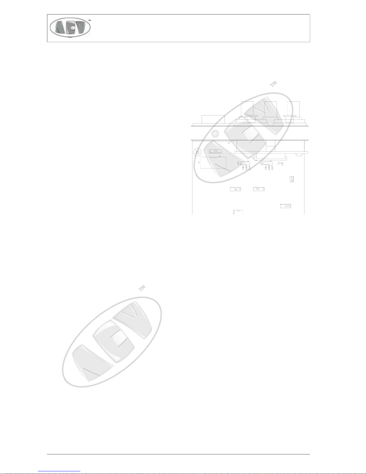
Pre-set of input impedance is easily done by accordingly selecting the jumpers JP1 and JP2, easily located
on the input board just on the rear of the input connectors, as shown in the drawing. Impedance selection
is silk-screened on the component mask of the board.
LF audio mono or stereo inputs are “XLR” female connectors. They should be connected to the output
of the mixing table, or to any audio-processor that drives it, with a balanced coaxial cable connected to pin
3 (+) and pin 2 (-). The cable shield, connected to the ground through of the driving equipment, has to be
connected to pin 1.
Pag. 22
SIRIO 2000TSIRIO 2000T
SIRIO 2000TSIRIO 2000T
SIRIO 2000T
Electronic Broadcast Equipment
In case of unbalanced drive, input pin 2 shall be short-circuited with ground and shield on pin 1, while
the signal shall be available on pin 3. Higher impedance selection, in this case, will be 5 kohm instead of 10
kohm.
With balanced drivings signals, the connecting canles
to the audio source may be far longer than 100-m.
Mpx or an externally processed signal, usually an
unbalanced one, can be connected to the female BNC
connector, marked "MPX", which is internally parallel
wired to the "RIGHT" channel connector: for this
reason it is not possible to connect signals to these two
connectors at the same time. Higher impedance
position is 5 kohm in this case too.
If the distance exceeds several tens of metres, use
75-ohm (RG59) or 92-ohm (RG62) cables.
The auxiliary-channel connector is also of the
grounded BNC female type. Use 50-ohm (RG58) or
75-ohm (RG59) cables for the connection to the
driver. The same applies to the monitor
"MODULATION" output, if needed.
Pre-emphasis setting
Low frequency mono and stereo channel signals have to be adequately “pre-emphasised”. Standard
preemphasis time constant is 50 and 75µs, the former being usually factory pre-set. Check whether this is
correct for your country (it is usually correct for any European country and most of the Pacific and South
American areas). It is not correct for USA standards, which requires 75µs.
If above correction is needed, simply set it on the "mode" FCC frame of the transmitter menu, which
also includes mono/stereo operation and frequency. See appropriate section further ahead on in this manual.
LF input level range, setting and requirements
In the following paragraph we will refer to 0 dBm as the audio signal which produces 1mW on 600 ohm,
i.e. a 775 mVrms / 2200 mVpp sine. Irrespective of the impedance and the non-sinus form of the signal,
we will continue to assume 0 dBm as a LF signal whose peak is + (or -) 1100 mV.
Pag. 23
SIRIO 2000TSIRIO 2000T
SIRIO 2000TSIRIO 2000T
SIRIO 2000T
Electronic Broadcast Equipment
In the same way, when talking about modulation, we will generally assume 0 dB as the signal which
produces 100% maximum allowed modulation, i.e. 75 kHz deviation.
There is no absolute worldwide standard regarding LF peak level as modulation signal for a transmitter,
nor for the mean deviation. Many broadcasters use 0 or +6 dBm as LF peak level for 100% modulation,
USA often uses +10 dBm.
Many European countries specify +6dBm for 40 kHz deviation (which is assumed to be a "mean"
modulation). This allows 5.5 dB headroom to 75 kHz (max) deviation, i.e. +11.5 dBm for 100%
modulation.
An higher level minimizes system and ambient noise but a too high level may over-stress the input circuitry
of the transmitter, reducing the dynamic distortion-free range over the nominal level (headroom). It may also
be costly to produce a broad sygnal with the required quality.
For this reason AEV S.P.A. recommends, whenever possible, to adopt +6 ÷ +11.5 dBm as nominal
peak level for audio modulation purpose.
SIRIO2000T transmitter series allows to set a "variabile" LF level on the main channel/s ranging -3.5 ÷
+12.5 dBm to be set for 100% modulation, with almost no difference in modulation performances, if high
quality signal is provided. Even at the higher level, at least +6 dB headroom is additionally allowed: i.e. up
to 150 kHz deviation, with no distortion. Obviously this deviation is not allowed by any broadcast standard
and the limiter threshold in this case should be set at its maximum to permit undistorted performance.
The auxiliary channel’s level ranges -12 ÷ +4 dBm to produce 10% modulation, i.e. 7.5kHz deviation.
Consequently typical input levels for an SCA-type signal (10% max. admissible deviation) are 0.2 ÷ 1.0 V
rms
/ 566 ÷ 2830 mVpp, when the input is set between -11.5 and +2.5 dB. All the same, an RDS-type signal
could be accommodated in the 0.052 ÷ 0.33 V
rms
/ 150 ÷ 930 mVpp level range, to produce the standard
peak deviation of 2 kHz, as above. In case a higher deviation is required for RDS (some broadcast
authorities set it to 3 or even 4 kHz deviation instead of the standard 2kHz ) a higher signal level preset
sensitivity of the auxiliary input, is needed.
Regulating the nominal input level for 0 dB modulation on the transmitter is an easy task. From the proper
menu field you can see the variation in real-time, while the input level is being adjusted, in 0,5dB steps. The
modulation is reported in kHz as absolute deviation, and in dB with reference to 75kHz.
In this field, the reported deviation includes any other auxiliary signal as pilot tone, when in stereo, and
RDS or SCA signals, if used at the moment. To measure only the audio input channel signal, go to the Left/
Right level menu.
The auxiliary channel level is equally easy to set, being measured as sensitivity in dB and as deviation in
kHz. Remember that, in this case, 0dB corresponds to 7.5kHz deviation, i.e. 10% max allowed total
standard modulation. In this way the typical level for RDS is -11.5dB for 2 kHz deviation. This menu field
accounts only for deviation due to auxiliary signal. To see the added effect on the total deviation, go to the
MPX menu.
Due to the peculiar characteristics of the RDS signal and the measuring sampling, the reading
is slow to stabilise in case of sudden level variarions and tends sometimes to slightly flicker in few
tenths of a dB. Allow enough time to stabilize and take the higher deviation reported as the right one.

Pag. 24
SIRIO 2000TSIRIO 2000T
SIRIO 2000TSIRIO 2000T
SIRIO 2000T
Electronic Broadcast Equipment
The transmitter’s internal limiter is peak-clipping type; this means that as soon at it cuts in, modulation
distortion increases sharply. For this reason, the modulation signal should be kept under control to prevent
intervention of the limiter. Anyway, do not over-estimate this problem: occasional action of the limiter is
mostly unperceivable.
The cut-in limiter threshold, when enabled, is factory pre-set to +2.5 dB (100 kHz peak value). It may
be set from 0 dB (75 kHz) up to +7.1 dB (170 kHz). This threshold value is mostly specified in the various
national standards, and tolerance to short over-modulating peaks varies from country to country. Some
countries do not permit the user to disable the limiter or change the level. Some countries do not allow the
user to disable the limiter or change its threshold. Note that the limiter action begins slightly after the preset level, with no action at all till that. The difference between the threshold level and hard clipping is some
0.5dB.
In any case, the modulation peak value that is internationally admitted for FM is 75 kHz for peaks that
are not extremely short. For this reason, the limiter’s cut-in threshold should never be too high. It is highly
recommended to use an external multi-band limiter to optimise modulation, with higher tolerance for any
audio-signal peaks. Such devices momentarily reduce the amplifier circuits’ gain if the threshold is exceeded
and prevent severe, significant distortion.
Any external compressor, limiter or audio meter must be frequency compensated with the same time
constant of the pre-emphasis to modulate or monitor deviation properly.
Therefore, as much as is possible, the audio level shall be constantly and correctly monitored and
adjusted to prevent the internal limiter from cutting in. Done it, on the other hand the audio level should be
as high as it is possible, to achieve the best signal/noise ratio, and presence effect, on reception.
The tendency to over-process audio signals is common in a number of local broadcasting stations:
if an amount of processing is advisable, and we recommend using a top grade one, do not to compress the
signal too much, as this impairs the original dynamics.
The audio response of the SIRIO2000T transmitter is extremely flat, without any perceivable loss on
low and high audio frequency: for this reason large frequency alterations of the audio signal supplied by using
a so-called “frequency equaliser” are not advisable. An increase of the low and high frequency contents of
the audio signal by more than a few dB might cause general degradation of modulation dynamics and
improper functioning of the limiter.
 Loading...