

CREATED ON: June 21, 2016
Instruction Manual
MPR-E1 V2.0
Motor Protection Relay
EAPL
Introduction
Self powered device, Displays 3 Phase voltage, current and frequency
during healthy condition.
Monitors and control Phase failure, Phase unbalance, Phase Reversal, over
voltage, under voltage, over current, under current, over frequency, u nder
frequency and Earth Leakage in 3 Phase 4 wire system.
Box Accessories
One (1) MPR-E1 V2.0 Monitoring Device
One (1) Instruction Manual
One (1) RC Filter
PARAMETERS
IN VOLTAGE,
CURRENT AND
FREQUENCY
R-V
Y-V
B-V
RY-V
YB-V
BR-V
R-A
Y-A
B-A
Hz
Safety Precautions
Read and follow all the safety precautions and instructions before
installing and working with the equipment.
! DANGER
HAZARD OF ELECTRIC SHOCK, EXPLOSION OR ARC FLASH
• Apply appropriate personal protective equipment(PPE) and foll ow
safety work practices
• Only qualified electrical workers should install this equipment. Such work
should be performed only after reading this entire set of instructions.
• If the equipment is not used in the manner specified by the
manufacturer, the protection provided by the equipment may be
impaired.
• NEVER work alone.
• Turn OFF all power supplying the monitoring device and the equipmen t
in which it is installed before working on it.
• The successful operation of this equipment depends upon proper
handling, installation and operation. Neglecting fundamental ins tallation
requirements may lead to personal injury as well as damage to
electrical equipment or other property.
• NEVER bypass external fusing.
• NEVER apply the voltages at Program Lock and Auto Reset terminals.
• Before performing Dielectric or Megger testing on any equipment in
which the monitoring device is installed, disconnect all the input and
output wires to the monitoring device. High voltage testing may
damage electronic components contained in the monitoring dev ice.
• The monitoring device should be installed in a suitable electrical
enclosure.
Failure to follow these instructions will result in death or serious injury.
• EAPL is not responsible for any consequential damages arising ou t of use
of our products, though the technology is cautiously chosen and
implemented like any other well designed good electric device.
Installation
Connecting cable recommendations
Insulation rating Current rating
Voltage circuit >600 VAC > 0.1A
Current circuit >600 VAC >7.5A/2.5mm2/
14AWG minimum
Tools and Fasteners
Kindly use star – type screw driver for tightening the screws.
NOTE:
Installation should include a disconnecting device, like switch or
circuit breaker, with clear ON/OFF markings, to turn-off the auxiliary
supply (control power).The disconnecting device should be with in the
reach of the equipment and the operator.
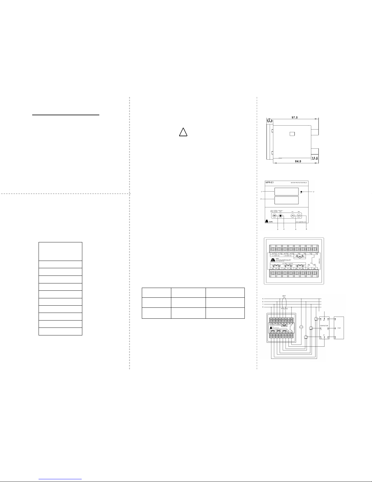
Dimension
Note: All Dimensions are in mm.
Front Panel
Rear View
Wiring
System Type : Star/Wye
1. Top Display Window
2. Bottom Display Window
3. MENU/ ENTER/
HOLD/SCROLL Button
4. MANUAL/ESC Button
5. INC Button
6. DEC Button
7. RLY
OD RE NN 610002 REV 02/21-06-16
Page 1 of 2
1,2,3,4 - R ,Y,B,N
5 , 6 - CBCT
8 - Com
9,10 - S1, S2 (R phase)
11, 12 - S1, S2 (Y phase)
13, 14 - S1, S2 (B phase)
15, 16 - NO, NC
CREATED ON: June 21, 2016
Keys and Operation
RUN Mode
1. On power application, relay will be in NC condition for
approximately 10sec.
2. During healthy condition, all the voltage parameters shall be
displayed with instantaneous values. Relay and relay LED will
be in ON or OFF condition depending on Rly ’y’ or Rly ‘n’ set ting.
3. During fault condition, type of fault shall be displayed with
Relay OFF or ON Status depending on Rly ’y’ or Rly ‘n’ setting.
Auto mode
4. Once the fault is recovered, unit automatically comes bac k
to parameter display mode as mentioned in point – 2.
Manual mode
5. Once the fault is recovered, manual key to be pressed to
bring back display mode as mentioned in point – 2.
6. If faults are rectified before set trip delay timings of relay,
display will continue to show fault status. Relay status remain
unaltered. Press Manual key to show the parameter display .
Press MENU/ENTER key for 3Seconds to HOLD/SCROLL displ ay.
When fault occurs unit display’s the following:
Parameters
Top
display
Bottom
display
OVER VOLTAGE Err OUOL
UNDER VOLTAGE Err UUOL
OVER CURRENT Err OCrt
UNDER CURRENT Err UCrt
OVER FREQUENCY Err O-HZ
UNDER FREQUENCY Err U-HZ
EARTH LEAKAGE Err ELr
PHASE UNBALANCE Phs UbAL
PHASE REVERSE Phs rEU
R PHASE FAIL FAIL P-r
Y PHASE FAIL FAIL P-y
B PHASE FAIL FAIL P-b
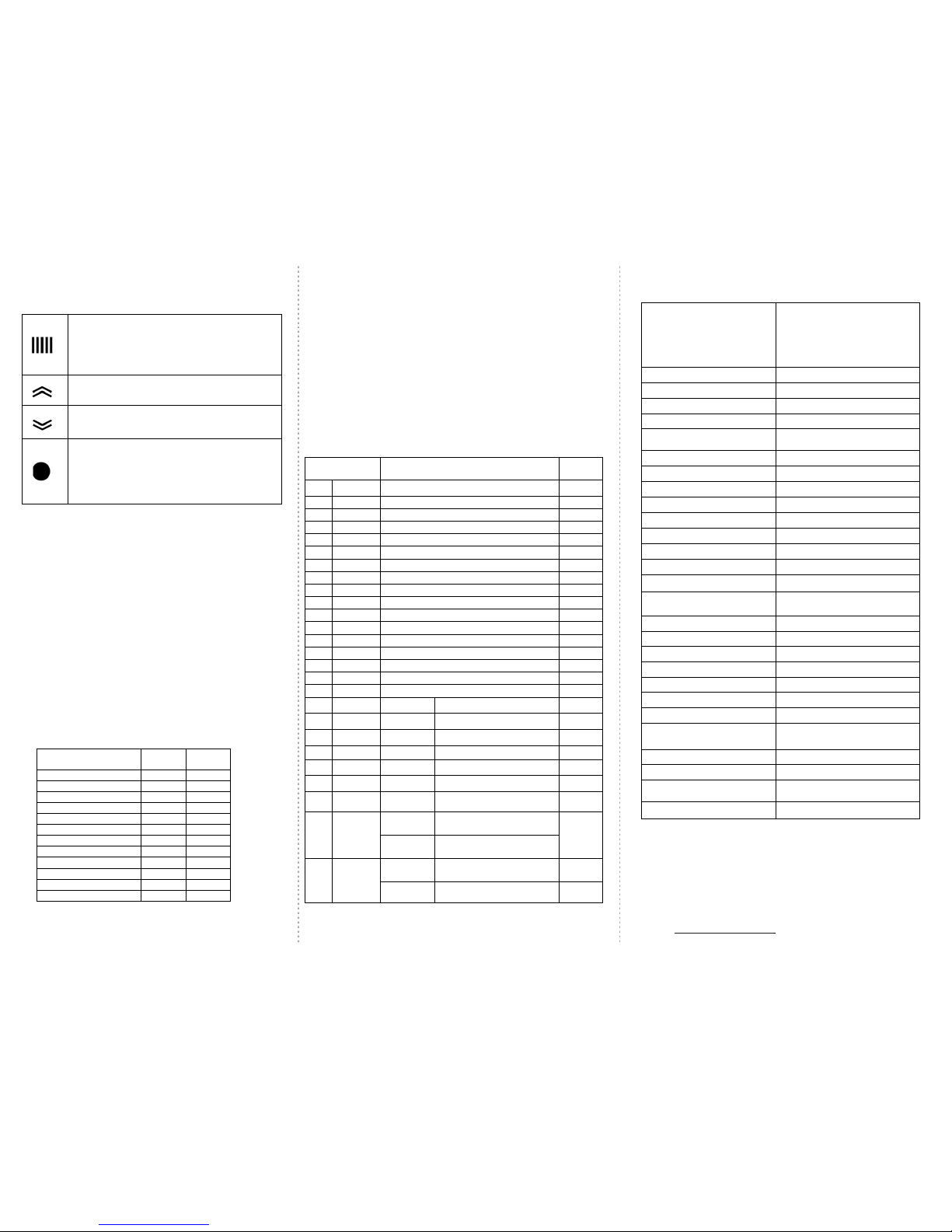
MENU/ENTER/HOLD/SCROLL Key
RUN Mode : Used to select scroll/hold the
parameters.
PROGRAM MODE : Used to enter into program
mode.
: used to select next parameters.
INC Key
PROGRAM Mode : Used to increase the values.
DEC Key
PROGRAM Mode : Used to decrease the values.
MANUAL/ESC Key
RUN Mode : When fault recovery happens this
key shall be used to Load ON/OFF manually.
PROGRAM Mode: It is used to view the previous
parameters.
Phase Unbalance Condition
To set unbalance condition for 20%.
Set 20 in unit (PUbL=20 as shown in the table).
If RY=350V, YB=450V, BY=319V in the load.
Fault is created in the unit, upper displays shows “Phs” and
lower shows “UbAL”.
Calculations are as follows
Set nVOL=415V, PUbL=20% in the unit.
Vry=350V, Vyb=450V, Vbr=319V, Vavg= 373V
Vry -Vavg=23V, Vyb -Vavg=77V, Vb-Vavg=54V
Phase unbalance= (Maximum deviation / Vavg) * 100
= (77/373)*100= 20 %
PROGRAM Mode
To enter program mode press INC & DEC key simultaneously for 4sec.
Programming
Parameters
Range
Factory
setting
1
“nUOL”
Nominal voltages: 415V
415
2
“OUOL”
Over Voltage. Range: 5 to 100V 030
3
“UUOL”
Under voltage. Range: 5 to 100V 030
4
“CT-P”
CT Primary. Range: 5 to 2500A 005
5
“nCrt”
Nominal Current. Range: 0.5-500A 005.0
6
“OCrt”
Over Current. Range: 105-800% 120
7
“UCrt”
Under Current. Range: 20-95% 20
8
“ PUbl”
Phase Unbalance. Range: P 1-20% 20
9
“O-Hz”
Over frequency. Range: 2 to 5Hz
05
10
“U-Hz”
Under frequency. Range: 2 to 5Hz
05
11
“ELr”
Earth leakage current. Range: 1 to 8A
1
12
“IrdY”
Inrush delay. Range: 1-60sec 01
13
“ tdOU”
Trip delay Over Voltage. Range: 1- 250sec 005
14
“ tdUU”
Trip delay Under Voltage. Range: 1 - 250sec 005
15
“ tdOC”
Trip delay Over Current. Range: 1 - 250sec 005
16
“ tdUC”
Trip delay Under Current. Range: 1 - 250sec 005
17
“tdUb”
Trip delay Unbalance. Range: 1 – 250sec 005
18
bYPS
“OUL Y/n” Bypass Over Voltage
n
19
bYPS
“UUL Y/n” Bypass Under Voltage
n
20
bYPS
“OCt Y/n” Bypass Over Current
n
21
bYPS
“UCt Y/n” Bypass Under Current
n
22
bYPS
“UBL Y/n” Bypass Phase Unbalance
n
23
bYPS
“OHz Y/n”
Bypass Over Frequency
n
24
bYPS “UHz Y/n”
Bypass Under Frequency n
25 CntL
rLY ‘n’
Relay & Status LED OFF in
healthy condition
y
rLY ‘Y’
Relay & Status LED ON in
healthy condition
26 “Auto”
rst ‘Y’
Auto reset enable “Y”
rst ‘n’
Auto reset disable
(Manual mode)
“n”
Technical Specification
Disposition
Once the product life is over, you may send back the
unit to EAPL for disposition
Contact
Electronic Automation Pvt. Ltd
#20, KHB Industrial Area
Yelahanka, Bangalore -560064
Ph: +91-80-28567561/2, /42802345
Email: info@eaplindiamail.com,
www.eaplindia.com
Function
Phase Unbalance, Phase
Reversal, Phase Failure, Under
and Over Voltage, Under and
Over Current, Under and Over
Frequency, Earth Leakage
Monitor and Control.
System Input
Input Voltage 415V AC(3Ph-4W)
Input Current Current input (AR,AY,AB) Ib=5A
Input Frequency
50 Hz, ± 10%
Control output
1c/o rated for 10A @
250VAC/28VDC resistive load
Power Consumption 5VA/ 1W
Accuracy
Voltage
± 4V of display value
Current
± 5% of Ib ± 1 digit (Ib = 5A)
Frequency
± 2% of FS ± 1 digit
Trip Time
±1% of set delay ± 2 sec
Earth leakage current
±500mA of setting accuracy.
General
Minimum sensing current 0.5A
Maximum sensing current
5A(Above 5A> Ext.CT can be
used)
Earth leakage Trip time delay
5 sec Earth leakage
Phase Failure trip time delay
< 5 sec
Phase reverse trip time delay
Instantaneous
Frequency trip time delay
Instantaneous
Recovery Time 2 sec M in
Power On Delay
10 sec Max
Mode of Operation
Auto/ Manual
Core Balance Current
Transformer type
Toroidal core
CBCT Size Internal Diameter
100mm
Climatic
Ambient Temperature
Operation:
-
10°
C to +55
°
C
Storage : -25° C to +80° C
Humidity
MAX 85% RH @ 40° C
OD RE NN 610002 REV 02/21-06-16
Page 2 of 2
 Loading...