

Page 1
Issue 10.2016
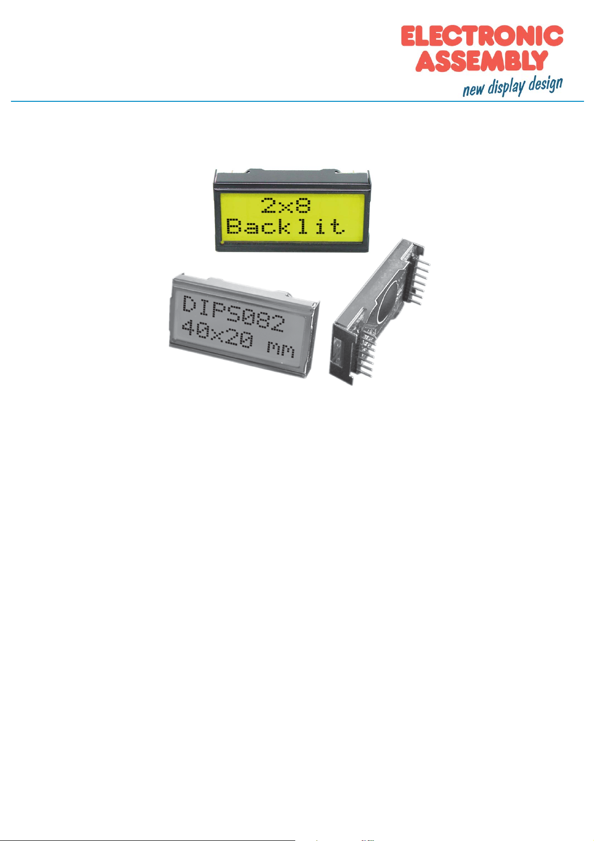
LCD-Modul 2x8 - 5.01mm
INCL. CONTROLLER ST7066
no more mounting
required
Dimension 40 x 20 mm
FEATURES
* SUPER SMALL LCD MODULE
* HIGH CONTRAST LCD-SUPERTWIST DISPLAY (BLUE/NEUTRAL)
* OPTIONAL LED-BACKLIGHT YELLOW/GREEN
* HD 44780 COMPATIBLE
* 4- OR 8-BIT DATA BUS INTERFACE
* ASCII CHARACTER SET BUILT IN
* ALSO AVAILABLE: 1x8 LCD WITH SAME DIMENSIONS
* POWER SUPPLY +5V OR ±2.7V OR ±3.3V @2mA and 50mA for LED-B/L (5V)
* OPERATING TEMPERATURE RANGE EA DIPS082: -20…+70°C
* OPERATING TEMPERATURE RANGE EA 8081-A3N: 0…+50°C
* NO MORE MOUNTING REQUIRED: SIMPLY PLUG INTO PCB
ORDERING INFORMATION
LCD-MODULE 2x8 - 5.01mm EA DIPS082-HN
WITH LED BACKLIGHT YELLOW/GREEN EA DIPS082-HNLED
LCD-MODULE 1x8 - 7.15 mm EA 8081-A3N
Page 2

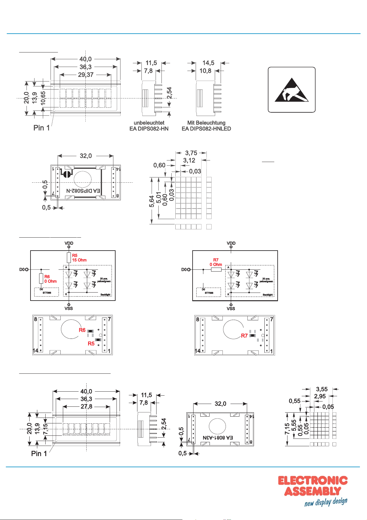
2x8 - 5.01mm
Pinout
Pin Symbol Level Function Pin Symbol Level Function
1 VSS L Power S upply 0V (GND) 8 D1 H/L Display Data
2 VDD H Power Supply +5V 9 D2 H/L Display Data
3 VEE - Contrast (about 0.3V / 1.2V) 10 D3 H/L Display Dat a
4 RS H/ L H= Data / L= Command 11 D4 (D0) H/L Dis play Data
5 R/W H/L H= Read / L=W rite 12 D5 (D1) H/L Display Data
6 E H Enable (falling edge) 13 D6 (D2) H/L Dis play Data
7 D0 H/ L Dis play Data / Anode LED-B/L 14 D7 (D3) H/L Display Data, MSB
Contrast setting
LED Backlight
Standard display EA DIPS082-HN is reflective, non-backlighted version. Module with part number
EA DIPS082-HNLED comes with yellow/green LED backlight. Power consumption for backlight is 50mA
typ. and 80mA max. Backlight is permanent switched on. Supply voltage with backlight is 5V only.
For individual use LED backlight can be switched on and off after doing the following modification:
Remove series resistor R5 and change resistor from R6 to R7. Now a positive voltage at pin 7 (D0)
powers Anode of backlight direct. To limit LED-current an external series resistor is required (R
0,8V / I
). Please note that in this case display interface is 4-bit mode only !
LED
Ext.
Table of commands
Code
Instruction
RS
DB7DB6DB5DB4DB3DB2DB1DB
R/W
Clear Display 0 0 0 0 0 0 0 0 0 1
Cursor At Home 0 0 0 0 0 0 0 0 1 *
Entry Mode Set 0 0 0 0 0 0 0 1 I/D S
Display On/Off
Control
Cursor / Display Shift 0 0 0 0 0 1
0 0 0 0 0 0 1 D C B
S/C R/L
Function Set 0 0 0 0 1 DL N F * *
CG RAM Address Set 0 0 0 1 ACG
DD RAM Address Set 0 0 1 ADD
Busy Flag / Address
Read
CG RAM / DD RAM
Data write
CG RAM / DD RAM
Data Read
0 1 BF AC
1 0 Write Data
1 1 Read Data
* *
Description
0
Clears all display and returns the cursor
to the home position (Address 0).
Returns the Cursor to the home
position (Address 0). Also returns the
display being shifted to the original
position. DD RAM contents remain
unchanged.
Sets the Cursor move direction and
specifies or not to shift the display.
These operation are performed during
data write and read.
Sets ON/OFF of all display (D) cursor
ON/OFF (C), and blink of cursor position
character (B).
Moves the Cursor and shifts the display
without changing DD RAM contents.
Sets interface data length (DL) number
of display lines (N) and character font
(F).
Sets the CG RAM address. CG RAM
data is sent and received after this
setting.
Sets the DD RAM address. DD RAM
data is sent and received after this
setting.
Reads Busy flag (BF) indicating internal
operation is being performed and reads
address counter contents.
Writes data into DD RAM or CG RAM
Reads data from DD RAM or CG RAM
Execute
Time
(max.)
1.64ms
1.64ms
40µs
40µs
40µs
40µs
40µs
40µs
-
40µs
40µs
=
Page 2
ELECTRONIC ASSEMBLY reserves the right to change specifications without prior notice.
Printing and typographical errors reserved.
Page 3
2x8 - 5.01mm
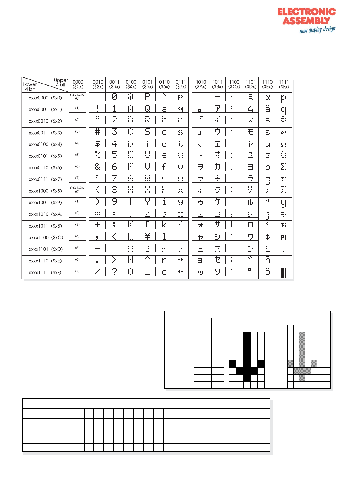
Character set
Below shown character set is already built in. Additionally 8 self defined characters can be attached.
CREATING YOUR OWN CHARACTERS
All character display modules offered in this catalogue, are able to create 8 own characters (ASCII Codes 0..7) in
addition to the 192 ROM fixed codes.
1.) The command "CG RAM Address Set" defines the
ASCII code (Bit 3,4,5) and the dot line (Bit 0,1,2)
of the new character. Example demonstrates
creating ASCII code $00.
2.) Doing 8 times the write command "Data Write"
defines line by line the new character. 8th. byte
stands for the cursor line.
3.) The new defined character can be used as a "normal" ASCII code (0..7); use with "DD RAM Address
Set" and "Data Write".
Adresse im CG RAM setzen Daten des Zeichens
Adresse Hex
01000
7 6 5 4 3 2 1 0
000 $40
001 $41 0 0 1 0 0 $04
010 $42 0 0 1 0 0 $04
011 $43 0 0 1 0 0 $04
100 $44 1 0 1 0 1 $15
101 $45 0 1 1 1 0 $0E
110 $46 0 0 1 0 0 $04
111 $47 0 0 0 0 0 $00
XXX
Bit
0 0 1 0 0 $04
Hex
INITIALISATION FOR A 2 LINE DISPLAY / 8-BIT MODE
Command
Functi on Set
Display ON/OFF
Clear Display
EntryMode Set
RS R/ DB DB DB DB DB DB DB DB
0 0 0 0 1 1 1 0 0 0
0 0 0 0 0 0 1 1 1 1
0 0 0 0 0 0 0 0 0 1
0 0 0 0 0 0 0 1 1 0
Remark
8-Bit Data Length, 2/4 lines, 5x7 Font
Display on, Cursor visible, Cursor blink
Clear Display, Cursor Home
Cursor Auto-Increment
Printing and typographical errors reserved.
ELECTRONIC ASSEMBLY reserves the right to change specifications without prior notice.
Page 3
Page 4
2x8 - 5.01mm
Dimensions
all dimensions are in mm
Technische Änderung vorbehalten.
Wir übernehmen keine Haftung für
Druckfehler und Applikationsbeispiele.
ATTENTION
handling precautions!
Note:
LC-displays are not suited for
wave soldering or reflow
soldering. Temperatures
above +80°C may damage
lcd-module.
LED intern / extern
1-line Display EA 8081-A3N
Delivery state
Intern, LED permanent on
Extern, LED controllable,
only possible in 4-bit mode
ELECTRONIC ASSEMBLY GmbH
Zeppelinstraße 19
D-82205 Gilching
Germany
Fon: +49 (0)8105-77 8090
Fax: +49 (0)8105-7780 99
e-Mail: info@lcd-module.de
Web: www.lcd-module.com
 Loading...