

Electronic S 100/25, S 120/25, S140/25AV, S 140/25 Instructions For Installation And Use Manual

ISTRUZIONI PER L'INSTALLAZIONE E L'USO
INSTRUCTIONS FOR INSTALLATION AND USE
INSTRUCTIONS POUR L'INSTALLATION ET MODE D'EMPLOI
INSTALLATIONS- UND GEBRAUCHSANWEISUNG
INSTRUCCIONES PARA LA INSTALACIÓN Y EL USO
STIRATRICE A RULLO
ROLLER IRONER
REPASSEUSE A CYLINDRE
WALZENBÜGELMASCHINE
MÁQUINA DE PLANCHAR A CILINDRO
S 100/25 - S 120/25
S 140/25 - S140/25AV
VIA MASIERE, 211/C
32037 - SOSPIROLO (BL)
ITALY
®
STIRO-25.10
grandimpiantigrandimpianti
grandimpiantigrandimpianti
grandimpianti
Industrial Laundry EquipmentIndustrial Laundry Equipment
Industrial Laundry EquipmentIndustrial Laundry Equipment
Industrial Laundry Equipment
"ELECTRONIC"


3
GB
I
1 Premessa e garanzia ............................................ 4
2 Introduzione ........................................................ 4
3 Prescrizione, divieti ed usi diversi della macchina 5
ISTRUZIONI PER L’INSTALLATORE
4 Trasporto, disimballaggio ed immagazzinamento 5
5 Messa in servizio ................................................. 5
ISTRUZIONI PER L’OPERATORE
6 Indicazioni relative alla macchina ....................... 6
7 Indicazioni relative all’uso della macchina ......... 7
ISTRUZIONI PER IL MANUTENTORE ED IL
RIPARATORE
8 Manutenzione straordinaria ed approvvigionamento
pezzi di ricambio ................................................. 8
9 Messa fuori servizio, smantellamento,
eliminazione della macchina ............................. 10
Dati tecnici ............................................................. 39
Figure ..................................................................... 40
Legenda componenti elettrici ................................ 42
Schemi elettrici ...................................................... 45
Disegni esplosi e ricambi ....................................... 52
1 Foreword and guarantee ................................... 12
2 Introduction ....................................................... 12
3 Prescriptions, restrictions and other uses ......... 12
INSTRUCTIONS FOR THE USER
4 Shipping, unpacking and storing the machine . 12
5 Machine start-up ............................................... 12
INSTRUCTIONS FOR THE USER
6 Machine information......................................... 13
7 Machine operation ............................................ 13
INSTRUCTIONS FOR MAINTENANCE AND
REPAIR WORKERS
8 Extraordinary maintenance and ordering
spare parts ......................................................... 15
9 Decommissioning, dismantling and disposal ... 16
Technical details .................................................... 39
Figures ................................................................... 40
Key to electrical components ................................ 42
Wiring diagrams .................................................... 45
Exploded views and spare parts ............................ 52
F
1 Avant-oriois et garantie ............................... 17
2 Introduction ................................................. 17
3 Prescriptions, interdictions et utilisations .... 18
DIFFÉRENTES DE LA MACHINE
INSTRUCTIONS POUR L’INSTALLATEUR
4 Transport, déballage et stockage
de l’appareil ................................................. 18
5 Mise en service de l’appareil ....................... 18
INSTRUCTIONS POUR L’OPÉRATEUR
6 Informations sur l’appareil .......................... 19
7 Indications sur l’utilisation de l'appareil
et sur l’entretien ordinaire ........................... 20
INSTRUCTIONS POUR LE PERSONNEL
RESPONSABLE DE L’ENTRETIEN ET DES
RÉPARATIONS
8 Indication pour l’entretien extraordinaire
et l’acquisition de pièces détachées ............. 21
9 Mise hors service, démontage et élimination
de l’appareil ................................................. 23
Données techniques ......................................... 39
Figures ............................................................. 40
Légende composants électriques ..................... 42
Schémas électriques ......................................... 45
Vues éclatées et pieces détachées .................... 52
D
1 Vorwort et Garantie .........................................24
2 Einführung ....................................................... 25
3 Vorschriften, Verbote, verschiedene
hinweise für den gebrauch des Gerätes ........... 25
ANWEISUNGEN FÜR DEN INSTALLATEUR
4 Hinweise für Transport, auspacken, aufstellen
und lagern des Gerätes .................................... 25
5 Hinweise für die Inbetriebnahme des Gerätes 26
ANWEISUNGEN FÜR DEN BENUTZER
6 Hinweise zum gerät ......................................... 26
7 Hinweise für den Gebrauch und die
Wartung des Gerätes ....................................... 27
ANWEISUNGEN FÜR DEN WARTUNGS- UND
TECHNISCHEN KUNDENDIENST
8 Hinweise für die Instandhaltung des Gerätes
und die Bestellung von Ersatzteilen ................ 29
9 Hinweise für Ausserbetriebnahme, Abbau ......30
und Entsorgung des Gerätes
Technische Daten .................................................39
Abbildungen ......................................................... 40
Zeichenerklärung für Einbauteile ......................... 42
Schaltpläne ........................................................... 45
Explosionszeichnungen und Ersatzteile ............... 52
E
1 Premisa y garantía .......................................... 32
2 Introducción .................................................... 33
3 Prescripciones, prohibiciones y otros usos
de la máquina ..................................................33
INSTRUCCIONES PARA LOS INSTALADORES
4 Transporte, desembalaje y depósito de la
máquina .......................................................... 33
5 Puesta en marcha de la máquina ..................... 33
INSTRUCCIONES PARA LOS UTILIZADORES
6 Indicaciones sobre a la máquina ..................... 34
7 Uso de la máquina .......................................... 35
INSTRUCCIONES PARA LOS ENCARGADOS
DEL MANTENIMIENTO Y DE LAS
REPARACIONES
8 Indicaciones para el mantenimiento extraordinario
y el abastecimiento de repuestos ................... 36
9 Indicaciones para la puesta fuera de servicio,
el desmantelamiento y la eliminación de
la máquina ...................................................... 38
Datos técnicos ....................................................... 39
Figuras .................................................................. 40
Leyenda de componentes eléctricos ..................... 42
Esquemas eléctricos ..............................................45
Diseños de despiece y repuestos ........................... 52

4
1. PREMESSA E GARANZIA
1.1 PREMESSA
Desideriamo ringraziarvi della preferenza
accordataci con l'acquisto della nostra
macchina.
Siamo certi che otterrete le migliori
soddisfazioni e garanzie se seguirete
attentamente le indicazioni contenute nel
presente manuale.
V'informiamo inoltre che in qualsiasi caso il
testo di riferimento per eventuali
contestazioni o osservazioni rimane quello
in lingua originale del costruttore, ovverosia
l'Italiano.
1.2 PRESCRIZIONI ED AVVERTENZE
Quest'apparecchio non è utilizzabile da
persone (inclusi bambini) con ridotte capacità
fisiche, sensoriali, mentali o con scarsa
esperienza e conoscenza a meno che non
siano visionati od istruiti sull'uso
dell'apparecchio dalla persona
adeguatamente formata che è responsabile
per la sua/loro sicurezza.
Questo manuale è da considerarsi parte
integrante dell'apparecchiatura e deve essere
conservato accompagnando l'apparecchio
stesso nel caso questo passi di proprietà.
Disattivare l'apparecchiatura in caso di guasto
e/o di cattivo funzionamento.
Durante l'uso la pulizia e la manutenzione si
deve prestare attenzione a non accedere con
arnesi e tanto meno con le mani a parti in
movimento (motore, cinghie, catene ed
ingranaggi).
In caso d'incidenti la ditta costruttrice non si
assume alcuna responsabilità per danni
all'operatore o ad altri persone che avvengano
durante l'uso, la pulizia e la manutenzione
dell'apparecchiatura.
Per le lavabiancheria, fare attenzione a non
aprire il dispenser durante il funzionamento
della macchina.
Porre particolare attenzione a tutte le parti
calde delle apparecchiature, quali tubi di
raccordo e di scarico dei fluidi di
alimentazione solitamente posti nel retro,
vetro oblò e, dove presenti, camini di
evacuazione delle fumane.
L'apparecchiatura è stata progettata per il
trattamento di tessuti secondo le indicazioni
riportate sulle etichette degli indumenti stessi,
trattare solo indumenti, biancheria per la
casa e tessuti normali da uso quotidiano.
Non trattate capi che siano stati a contatto
con prodotti chimici o infiammabili,
provvedete prima a un lavaggio a mano e
asciugateli all'aria per far evaporare
completamente queste sostanze.
L'uso di qualunque apparecchio elettrico ed
elettronico comporta l'osservanza di alcune
regole fondamentali. In particolare:
· Non toccare l'apparecchio con mani e
piedi bagnati o umidi.
· Non usare l'apparecchio a piedi nudi.
· Non lasciare esposto l'apparecchio agli
agenti atmosferici (pioggia, sale,
salsedine, ecc.).
· Non permettere che l'apparecchio sia
usato da bambini o da incapaci senza
un'adeguata sorveglianza.
· Non fumare in prossimità
dell'apparecchiatura durante l'uso.
· Non rimuovere o scavalcare i dispositivi
di sicurezza.
· Non utilizzare mai getti d'acqua diretti
od indiretti sulla macchina, fare
attenzione pertanto a non installarla in
prossimità di zone in cui è possibile
questa evenienza.
· NON utilizzare l'apparecchiatura se non
siete stati addestrati all'uso della stessa.
OGNI ALTRO USO NON
ESPLICITAMENTE INDICATO E' DA
CONSIDERARSI PERICOLOSO.
IL COSTRUTTORE NON PUÒ ESSERE
RITENUTO RESPONSABILE PER
EVENTUALI DANNI DERIVANTI DA
USO IMPROPRIO, ERRONEO ED
IRRAGIONEVOLE O COMUNQUE NON
RIPORTATO NEL PRESENTE
MANUALE.
1.2.1 SPECIFICITA' PER I MODELLI
DOTATI DI RISCALDAMENTO A
GAS
1.2.1.1 AVVERTENZE GENERALI
Leggere le istruzioni tecniche di installazione
prima di installare l'apparecchio.
Leggere le istruzioni per l'utilizzatore prima
di accendere l'apparecchio.
L'apparecchiatura deve essere installata solo
in un ambiente che soddisfi i necessari
requisiti di ventilazione.
L'utilizzatore dell'apparecchio non deve
manomettere i componenti sigillati della
macchina.
Per eventuali regolazioni o interventi su
qualsiasi componente relativo al circuito
gas, avvalersi di un tecnico qualificato e
abilitato all'intervento.
La rimozione o alterazione dei sigilli della
macchina fanno decadere la garanzia
dell'apparecchio.
1.2.1.2 INSTALLAZIONE
L'installazione della macchina dotata di
riscaldamento a gas ed il primo avviamento
dell'apparecchiatura, debbono essere eseguiti
da un tecnico qualificato ed abilitato che
provvederà alla verifica della correttezza
dell'installazione e procederà alla verifica
dei parametri di combustione con l'ausilio
dell'idonea strumentazione.
Qualora siano necessarie eventuali
regolazioni alle parti sigillate, per tarature,
cambio tipo di gas o altro motivo,
esse dovranno essere realizzate solamente
del tecnico abilitato che, al termine delle
operazioni di regolazione, procederà a
ripristinare i sigilli delle parti regolate e
rilasciare regolare rapporto da conservare
unitamente al manuale della macchina.
Unitamente all'apparecchiatura dotata di
riscaldamento a gas, è allegato il corredo
necessario al cambio del tipo di famiglia di
gas costituito da:
- Diaframma per gas della seconda famiglia
ed installazioni in Francia e Belgio (G20/
G25).
- Set ugelli calibrati peri vari gruppi di gas
(v.tabella allegata al presente manuale).
- Set adesivi per il cambio gas, da applicare
alla targhetta dati (sulla macchina e sul
manuale) come indicato nell'ultima pagina
del presente manuale.
La nuova targhetta dati riportante la modifica
della famiglia di gas deve essere applicata in
modo da coprire integralmente le indicazioni
precedenti riportate nella targhetta matricola
originale posta nella parte posteriore
dell'apparecchiatura e nell'ultima pagina del
presente manuale.
Il cambio della famiglia di gas con cui è
alimentata la macchina deve essere eseguita
solamente da un tecnico abilitato.
1.3 GARANZIA
- La garanzia ha una durata di mesi dodici
(12) dalla data di acquisto
dell'apparecchiatura o parte integrante della
stessa.
- La garanzia consiste nella sostituzione
delle parti eventualmente difettose per
accertate cause di fabbricazione e applicata
direttamente dal vostro fornitore.
- La mano d'opera è sempre a carico
dell'acquirente come pure le spese di
spedizione, imballo e rischi di trasporto.
- La garanzia è subordinata alla restituzione
dei pezzi avariati in PORTO FRANCO ed
alla contemporanea comunicazione dei dati
riguardanti il modello, il numero di matricola
ed il difetto della macchina sulla quale il
particolare era montato.
- La garanzia non si applica alle
apparecchiature che siano state danneggiate
per negligenza, errato collegamento, installo
inadatto, mancata osservanza delle istruzioni
di montaggio o impiego e comunque alterate
da personale non autorizzato. Non si applica
inoltre qualora il numero di matricola sia
stato alterato, cancellato o asportato o non
sia conosciuto.
- Non si applica la garanzia sul seguente
materiale:
a) Parti soggette alla normale usura quali
cinghie.
b) Membrane delle elettrovalvole e parti di
gomma in generale.
c) Elementi elettrici quali motore, bobine,
contattori, resistenze ecc.
2. INTRODUZIONE
Il presente manuale è stato realizzato in
modo semplice e razionale affinché
leggendolo conosciate a fondo la vostra
apparecchiatura. Si raccomanda di leggere
attentamente il contenuto e di conservarlo
ISTRUZIONI PER L'INSTALLAZIONE E L'USO
I

5
unitamente all'apparecchiatura. Le
avvertenze e le attenzioni contenute in questo
manuale, non possono coprire tutte le
eventualità; è importante tenere presente
che buon senso attenzione e prudenza sono
fattori che non possono essere aggiunti
all'apparecchiatura da parte del costruttore,
ma devono essere previsti dalle persone che
effettuano l'installazione la manutenzione e/
o uso della macchina.
Qualsiasi persona utilizzi
quest'apparecchiatura dovrà leggere il
presente manuale d'uso.
In caso di interventi sulla macchina la
presente ditta raccomanda vivamente di usare
pezzi di ricambio originali, per la cui
ordinazione si consiglia di consultare il
relativo paragrafo a fine manuale.
Le descrizioni ed illustrazioni contenute nel
presente manuale non si intendono
impegnative; la ditta pertanto si riserva il
diritto in qualunque momento e senza
impegno, di aggiornare tempestivamente la
pubblicazione e/o di apportare eventuali
modifiche ad organi, componenti e accessori,
nel caso in cui questo venga ritenuto
conveniente per un miglioramento o per
qualsiasi esigenza di carattere costruttivo o
commerciale.
3. PRESCRIZIONI , DIVIETI ED USI
DIVERSI DELLA MACCHINA
Durante l’uso la pulizia e la manutenzione
si deve fare attenzione a non accedere con
arnesi e tantomeno con le mani a parti in
movimento (motore, catena). In caso di
incidenti la ditta costruttrice non si assume
alcuna responsabilità per danni all’operatore
o ad altri persone che avvengano durante
l’uso, la pulizia e la manutenzione della
macchina.
L’uso di qualunque apparecchio elettrico ed
elettronico comporta l’osservanza di alcune
regole fondamentali. In particolare: non
toccare l’apparecchio con mani e piedi
bagnati o umidi. Non usare l’apparecchio a
piedi nudi , non lasciare esposto
l’apparecchio agli agenti atmosferici
(pioggia, sale, salsedine, etc.). Non
permettere che l’apparecchio sia usato da
bambini o da incapaci senza una adeguata
sorveglianza. Non si possono stirare capi di
biancheria sensibili al calore con una
temperatura troppo elevata. Non si devono
stirare capi di biancheria con uno spessore
superiore agli 8 mm o non idonei alla stiratura
con questo tipo di macchina o con una umidità
superiore a quella indicata. Non fumare in
prossimità della stiratrice o durante l’uso.
Non rimuovere o scavalcare i dispositivi di
sicurezza. Non lasciate nulla sopra la parte
riscaldante nemmeno a fine stiratura in
quanto la conca impiega parecchio tempo a
raffreddarsi. Non utilizzare mai getti d’acqua
diretti od indiretti sulla macchina, fare
attenzione pertanto a non installarla in
prossimità di zone in cui è possibile questa
evenienza.
OGNI ALTRO USO NON
ESPLICITAMENTE INDICATO IN
SEGUITO E’ DA CONSIDERARSI
PERICOLOSO ED IL COSTRUTTORE
NON PUÒ ESSERE RITENUTO
RESPONSABILE PER EVENTUALI
DANNI DERIVANTI DA USO
IMPROPRIO, ERRONEO ED
IRRAGIONEVOLE.
TOGLIERE L'ALIMENTAZIONE
ALL'APPARECCHIO PRIMA DI
QUALSIASI OPERAZIONE DI
MANUTENZIONE.
ISTRUZIONI PER
L’INSTALLATORE
4. INDICAZIONI RELATIVE AL
TRASPORTO, DISIMBALLAGGIO
ED IMMAGAZZINAMENTO DELLA
MACCHINA
4.1 TRASPORTO MACCHINA
Se è necessario un eventuale trasporto e/o
spedizione della macchina è utile seguire
attentamente le seguenti raccomandazioni:
Qualora si debba trasportare
l’apparecchiatura all’interno di un edificio
utilizzare esclusivamente l’apposito bancale
o uno equivalente; utilizzare un carrello
elevatore a mano oppure elettrico idoneo al
trasporto di queste macchine e con capacità
di sollevamento sufficiente (vedi dati tecnici).
Controllare che la stiratrice possa superare
tutti gli ostacoli es. scale, porte etc. Non
trascinate mai la macchina per i fianchi o
per qualsiasi altra parte.
Nel caso in cui la macchina debba essere
spedita utilizzare esclusivamente l’imballo
originale che aiuta a garantire sufficiente
stabilità alla macchina durante il trasporto.
4.2 IMMAGAZZINAMENTO
Qualora la macchina dovesse rimanere in
deposito per lungo tempo prima di essere
utilizzata lasciarla all’interno del suo imballo
originale il quale garantisce una ottima
protezione. Assicurarsi inoltre che le
condizioni ambientali siano corrispondenti
a quelle di cui al paragrafo 5.3. Nel caso in
cui invece debba rimanere ferma per lunghi
periodi dopo che è già stata usata; verificare
che sia materialmente scollegata dalla rete di
alimentazione elettrica e coprirla con il sacco
protettivo originale.
4.3 DISIMBALLAGGIO
1) Prima di prendere in consegna la macchina
dal trasportatore, controllare le condizioni
dell’imballo. Se il medesimo presenta danni
evidenti all’esterno, può darsi che anche la
macchina abbia subito delle conseguenze.
In tal caso sballate la macchina in presenza
del trasportatore stesso e firmate, con riserva,
la relativa bolla di consegna. Eventuali danni
dovuti al trasporto o ad errato stoccaggio
non sono da attribuire alla casa costruttrice
della macchina.
2) Disimballate la macchina con tutte le cure
atte ad evitare di danneggiarla. Per togliere
il bancale rimuovere le viti all’interno dei
fianchi destro e sinistro.
3) Montare l’asse in legno di appoggio
biancheria sui supporti utilizzando le viti
senza testa ed i suoi bulloni come da figura
6; con la testa della vite ed il lato più lungo
della tavola rivolti verso l’alto.
4) Accertatevi che non resti nell’imballo o
vada perduto il manuale di istruzioni. (esso
si trova normalmente all'esterno dell'imballo)
Gli elementi dell’imballaggio (sacchetti di
plastica, polistirolo, legno, cartone, chiodi
etc.) non devono essere lasciati
assolutamente alla portata dei bambini in
quanto fonti di potenziale pericolo; essi
devono essere raccolti e conservati per
eventuali futuri spostamenti della macchina
o per eventuali lunghi periodi di fermo
macchina (vedi paragrafo 4.2). Prima di
collegare l’apparecchio accertarsi che i dati
di targa corrispondano alle caratteristiche
della rete elettrica a cui deve essere collegata
la macchina stessa. L’apparecchio dovrà
essere destinato solo all’uso per il quale è
stato espressamente progettato.
5. INDICAZIONI PER LA MESSA IN
SERVIZIO DELLA MACCHINA
5.1 PRESCRIZIONI PER IL
POSIZIONAMENTO DELLA
MACCHINA
Le stiratrici non presentano alcun problema
di ubicazione all’infuori di un pavimento
livellato. Essendo inoltre a servizio
monofrontale, possono essere poste vicino
ad una parete.
Nella versione aspirata prevedere lo spazio
necessario per installare il camino di
evacuazione dei vapori generati durante la
stiratura (vedi fig.1).
Tramite i piedini posti sotto i fianchi mettere
in bolla la macchina facendo uso di una
livella appoggiata sui fianchi. Controllare
che il peso distribuito sui piedini sia uniforme
e che l’apparecchiatura non dondoli. Se
viene spostata l’apparecchiatura ripetere
l’operazione di livellamento.
5.2. SPAZIO NECESSARIO PER
L’INSTALLAZIONE, USO E
MANUTENZIONE MACCHINA (vedi
fig.1)
La stiratrice dovrà avere a disposizione lo
spazio minimo indicato nella figura 1:
1) Fronte macchina
2) Rullo stirante
3) Pannello controllo
4) Interruttore sezionatore automatico (non
compreso nella fornitura)*
5) Fianco contenente l'aspirazione
6) Connessione per collegamento

6
equipotenziale a disposizione
7) Ingresso alimentazione elettrica a mezzo
tubo protettivo
8) Tubo espulsione vapori
* La posizione dell’interruttore
sezionatore automatico deve essere tale
da poter essere facilmente azionato
dall’operatore in una situazione di
EMERGENZA (distanza massima mt 3).
5.3 CONDIZIONI AMBIENTALI
CONSENTITE PER IL CORRETTO USO
DELLA MACCHINA
(da far presente a chi utilizzerà la macchina)
- TIPO LOCALE: CHIUSO
- TEMPERATURA MINIMA: 10°C
- TEMPERATURA MASSIMA: 40°C
- UMIDITÀ RELATIVA: 75% U.R.
- ILLUMINAMENTO: 100 LUX (dato
valido per lo stato italiano, vista la non
omogeneità in materia di luminosità sugli
ambienti di lavoro per gli altri paesi rifarsi
alle singole leggi nazionali).
5.4 COLLEGAMENTO ELETTRICO
(vedi fig.2)
L’installazione deve essere effettuata
secondo le istruzioni del costruttore da
personale professionalmente qualificato e
conformemente alle norme sugli impianti
elettrici vigenti nei singoli paesi. Un’errata
installazione può causare danni a persone,
animali o cose, nei confronti dei quali il
costruttore non può essere considerato
responsabile.
Togliere il pannello posto sul fianco destro
fissato tramite le 4 viti con testa a croce,
accertarsi che la tensione di alimentazione
corrisponda ai dati di targa della stiratrice,
inoltre considerare che le variazioni massime
della tensione di alimentazione consentite
sono del ±10%.
IMPORTANTE:
E’ OBBLIGATORIO COLLEGARE LA
MACCHINA A TERRA. Per tale scopo,
all’interno, vi è un morsetto per il relativo
collegamento della TERRA. Quest’ultima
dovrà essere conforme alle norme di legge.
Il costruttore declina ogni responsabilità
qualora questa norma anti infortunistica
non venga rispettata.
In conformità alle più recenti norme
antiinfortunistiche la macchina è dotata di
morsetto esterno per connessione
equipotenziale a disposizione per il
collegamento.
E’ indispensabile inserire a monte
dell’apparecchiatura un interruttore
omnipolare sezionatore automatico con
distanza minima fra i contatti di 3 mm tarato
in base ai massimi assorbimenti vedi dati di
targa della apparecchiatura e tabella sotto:
Modello N° Corrente Corr. differ.
poli nomin. In intervento Id
100/25 4 10 A 30 mA
120/25 4 16 A 30 mA
140/25 4 16 A 30 mA
140/25AV 4 16 A 30 mA
ATTENZIONE:
Con le macchine dotate di inverter vi è una
dispersione verso terra di 5-8 mA, dovuta
all’installazione del filtro antidisturbo. Tale
dato è da tenere in considerazione qualora ci
siano più macchine collegate sulla stessa
linea.
Dimensionare i differenziali magnetotermici
in funzione del numero delle macchine
eventualmente collegate.
Predisporre un tubo passacavo tra
l’interruttore sezionatore e l’ingresso per
l’alimentazione elettrica della
apparecchiatura diametro esterno 20 mm.
Tale ingresso è dotato di uno stringitubo,
pertanto dopo aver inserito il tubo rigido
sarà necessario avvitare il dado dall’interno
della macchina. La macchina è fornita con
mt. 3 di cavo tipo FROR 450/750V 4G
4mm2. In caso di sostituzione, assicurarsi
che il cavo sia non propagante la fiamma ed
opportunamente protetto. Una volta inserito
il cavo avvitare lo stringicavo all’interno
dell’apparecchiatura.
La stiratrice viene collaudata presso la nostra
fabbrica rispettando il senso ciclico delle
fasi R-S-T (A1-A2-A3) (L1-L2-L3), tale
senso ciclico deve essere rispettato per non
recare danni alla stessa apparecchiatura.
Nelle apparecchiature dotate di inverter, il
collegamento ciclico delle fasi perde la sua
importanza, dato che l'inverter si autoregola.
La verifica può essere fatta anche
manualmente nel seguente modo:
- Controllare che la conca sia chiusa sul
rullo, in caso contrario togliere lo sportello
per l’apertura manuale di emergenza con
l’apposita chiave in dotazione e ruotare il
volantino sul motore in senso orario fino a
che la conca va a contatto con il rullo,
dopodichè richiudere lo sportello di
emergenza.
- Accendere l’interruttore sezionatore
generale a parete; se la conca si alzerà le fasi
sono connesse correttamente in caso
contrario invertire due delle fasi in ingresso.
IMPORTANTE: Comunicare al cliente o
all’utilizzatore o al responsabile tecnico
dell’impianto di lavanderia l’importanza
del senso ciclico corretto delle fasi in modo
da evitare che possano venire invertite
accidentalmente.
PER QUALUNQUE ROTTURA
PROVOCATA DA UNA ERRATA
INSTALLAZIONE LA GARANZIA
NON RISPONDE DEI DANNI.
ISTRUZIONI PER
L’OPERATORE
6. INDICAZIONI RELATIVE ALLA
MACCHINA (VEDI FIG.3)
6.1 DESCRIZIONE DELLA MACCHINA
La macchina è composta nelle sue parti
principali come mostra la figura 3 e più
dettagliatamente:
1) Fianco destro contenente gli organi di
movimento , quadro elettrico di comando
e prima molla a gas di spinta della conca.
2) Rullo rivestito con tessuto idoneo alla
stiratura.
3) Conca riscaldante in pressione sulla
biancheria.
4) Pedale a leva per abbassamento
automatico della conca.
5) Barra di sicurezza "salvadita" che una
volta alzata in situazione di pericolo
inverte il senso di rotazione del rullo ed
alza la conca.
6) Fianco sinistro contenente seconda
molla a gas di spinta della conca e
l'aspiratore (optional) per le macchine
che ne sono dotate.
7) Asse in legno sul quale si prepara la
biancheria da stirare prima di avvicinarla
al rullo in movimento.
8) Portina di accesso al sollevamento di
emergenza apribile a chiave.
9) Regolatore di riscaldamento con
indicazione a display della temperatura
della conca stirante.
10) Pulsante di START dotato di LED
luminoso verde.
11) Pulsante di STOP dotato di LED
luminoso giallo.
12) Punto luminoso indicate il
funzionamento del riscaldamento.
13) Pulsante a fungo.
14) Regolatore velocità con indicazione a
display del valore in uso.
15) Raccordo di uscita vapori da collegare
con l'esterno tramite un tubo avente il
diametro di 60 mm con la superficie interna
liscia nell'allacciamento. Porre particolare
attenzione a non installare più di 3-4 curve a
90° poiché l'aspirazione potrebbe risultare
quindi insufficiente.
Per l'ottenimento di un buon rendimento
della macchina si consiglia un percorso di
tubi la cui lunghezza non superi i 5-6 metri.
IMPORTANTE:
LA FIGURA 3 UNITAMENTE AGLI
SCHEMI RIPORTATI
SUCCESSIVAMENTE E’
INDISPENSABILE PER LA RICERCA
E L’ORDINAZIONE DELLE PARTI DI
RICAMBIO.
6.2 GAMMA COMPLETA DELLE
APPLICAZIONI
La stiratrice a rullo che avete acquistato è
stata progettata in modo da eseguire la
stiratura di tessuti sintetici di vario genere,
lana, cotone, lino e seta. Le temperature
devono essere opportunamente regolate
tramite il relativo termostato seguendo le
temperature da noi indicate.
6.3 INFORMAZIONI SULL’IMPIANTO
ELETTRICO
L’impianto elettrico a bordo macchina è
composto da apparecchiature di protezione

7
e controllo opportunamente inserite su di
una piastra nel fianco destro della macchina.
Gli schemi e le distinte relative sono riportati
successivamente.
6.4 DOCUMENTI ATTESTANTI LA
CONFORMITÀ DELLA MACCHINA
La stiratrice rullo descritta nel presente
manuale è conforme alle seguenie direttive:
73/23/CEE, 93/68/CEE
89/336/CEE, 92/31/CEE, 93/68/CEE
e normative:
EN 60335-1, EN 60335-2-44
EN 55014, EN 61000-3-2, EN 61000-3-3
EN55104
7. INDICAZIONI RELATIVE
ALL’USO DELLA MACCHINA
7.1 FUNZIONAMENTO
Dare tensione alla macchina agendo sia
sull’interruttore sezionatore automatico
generale a parete che su quello posizionato
sul fianco destro della macchina stessa.
Sul pannello di controllo si illuminerà la spia
gialla indicante che la macchina è alimentata.
Alla pressione del pulsante di START si
illumineranno il DISPLAY relativo
all’indicazione della temperatura e quello
relativo alla velocità selezionata (solo nei
modelli con variatore di velocità) unitamente
alla spia verde indicante che la macchina è
stata accesa.
REGOLAZIONE DELLA
TEMPERATURA
Sul pannello di controllo sono presenti tre
pulsanti che consentono la regolazione della
temperatura e sono “+”, “ - “ e “ SET “:
normalmente viene indicata la temperatura
reale della conca stirante istante per istante.
Alla pressione del pulsante “ SET “ viene
visualizzata la temperatura impostata che
lampeggia; alla pressione dei pulsanti “ + “
e “ - “ varia di conseguenza la temperatura di
lavoro prescelta. Dopo alcuni secondi che
non viene premuto alcun pulsante il
DISPLAY torna alla visualizzazione normale
e la conca stirante inizierà a riscaldarsi.
La temperatura, una volta arrivati a regime,
tende a stabilizzarsi in prossimità del valore
impostato con degli scostamenti minimi.
N.B. Una variazione di 5-8°C in più o in
meno non comporta alcuna variazione sulla
qualità della stiratura. All'atto
dell'introduzione dei primi capi da stirare la
temperatura calerà di diversi gradi per poi
tornare ad assestarsi al valore impostato.
Tale comportamento è da ritenere
assolutamente normale così come il continuo
accendersi e spegnersi del riscaldamento.
Nelle prime ore di funzionamento è possibile
che fuoriesca dalle feritoie del carter
copriconca dell’odore provocato dal
cambiamento di stato del materiale isolante
applicato alle resistenze al fine di contenere
il calore all’interno della conca stessa. Tale
odore non è assolutamente nocivo e cesserà
dopo poco tempo.
MOVIMENTO DELLA CONCA
STIRANTE
Premendo la pedaliera il rullo comincia a
ruotare nel senso di lavoro e la conca stirante
si abbassa fino ad arrivare in pressione sul
rullo stesso.
Per riportare la conca in posizione di riposo
si deve agire nuovamente sulla pedaliera
così da posizionarla in alto mentre il rullo
gira nel senso opposto a quello di lavoro.
Mentre la conca sta salendo per riposizionarsi
in alto è possibile invertire il senso di marcia
anche se non è stato ancora raggiunto il
punto di massima altezza. Questo
accorgimento consente una rapidità di lavoro
notevolmente superiore.
ATTENZIONE Dopo 20 minuti che non
viene premuta la pedaliera la macchina si
spegne autonomamente in modo da
ridurre al minimo il consumo energetico.
La conca verrà automaticamente portata
in posizione di riposo e sul pannello di
controllo l'unico segnale presente sarà
l'accensione del LED giallo del pulsante
di STOP.
REGOLAZIONE DELLA VELOCITÀ
VALIDO SOLO PER MODELLI
SPECIALI
La regolazione della velocità avviene agendo
sui due pulsanti contrassegnati dalle frecce
"" e “ “
La velocità di trascinamento è quindi
impostabile tra i 2 ed i 4 metri al minuto. Al
valore ”l” si ha la minima velocità per poi
incrementarla fino al valore ”7"
corrispondente al massimo.
La variazione della velocità di trascinamento
consente una maggiore versatilità della
macchina in rapporto ai diversi tipi di tessuto
da stirare.
FINE DELLA SESSIONE DI
LAVORO
Alla fine del lavoro è consigliabile lasciare
per qualche minuto il rullo in movimento
con la conca stirante a medio-bassa
temperatura in modo da eliminare l’umidità
residua dal rivestimento.
Per spegnere la macchina è sufficiente
premere il pulsante di “STOP” . Se la conca
è in posizione di riposo la macchina si spegne
normalmente mentre se il rullo sta girando
viene portata in alto la conca e quindi spenta
la macchina.
Dopo questa operazione si deve agire
sull’interruttore sezionatore a bordo
macchina e su quello automatico a parete in
modo da togliere tensione alla macchina.
FUNZIONAMENTO A GETTONIERA
In questa particolare configurazione la messa
in funzione della macchina avviene tramite
l’inserimento del gettone mentre lo
spegnimento avverrà non appena è trascorso
il tempo impostato. Le modalità di
spegnimento sono le stesse descritte sopra
ma vengono eseguite automaticamente senza
dover intervenire su alcun dispositivo.
Per impostare un valore diverso da quello
programmato in fabbrica seguire le istruzioni
allegate a questi modelli speciali.
ATTENZIONE Si raccomanda di non
lasciare MAI la conca stirante ad alta
temperatura a diretto contatto con il rullo
poiché ciò ne compromette notevolmente
la durata.
Si sottolinea poi che il pulsante di sicurezza
a fungo montato sulla macchina NON
deve essere utilizzato per spegnere la stessa
ma soltanto nei casi di effettivo pericolo
per l’utilizzatore.
7.2 CONSIGLI UTILI PER L’UTILIZZO
DELLA MACCHINA
Selezionare i capi da stirare dividendoli in
base alla loro composizione ed iniziare a
lavorare partendo da quelli che richiedono
una temperatura più bassa per poi arrivare ai
più resistenti al calore aumentando mano a
mano la temperatura con il termostato.
Ciò permette di iniziare prima il lavoro ed
evita di dover aspettare che la conca stirante
si raffreddi nel passaggio dalle alte alle
basse temperature.
Per ottenere dei buoni risultati la biancheria
da stirare deve avere un tasso di umidità
relativa compreso tra il 10% ed il 20%.
Nella versione S140/25 con rivestimento
lamellare tale intervallo aumenta dal 10%
fino al 40-45% grazie all’autoaspirazione ed
alla possibilità di regolare la velocità di
trascinamento (standard in questo modello).
Di seguito riportiamo una tabella indicativa
sulle temperature da impostare per i vari tipi
di tessuti e legata alla simbologia
normalmente usata dalle industrie tessili:
Tessuto Simbolo* Indice temp.
Temperat.
Perlon/seta • Bassa max. 110°C
artificiale
Seta-lana • • Media max. 150°C
Cotone-lino • • • Alta max. 200°C
200°C 150°C 110°C
* Questi simboli sono normalmente disegnati
sulle etichette dei tessuti all’interno di un
ferro da stiro.
ATTENZIONE: i capi trattati con amido
vanno stirati per ultimi. Premendo il
pulsante di “START’ si illumina il led verde
corrispondente indicante che la macchina è
pronta per essere utilizzata. Si deve ora
selezionare la temperatura desiderata
procedendo come descritto sopra. Al
raggiungimento della temperatura impostata
( con la conca stirante in posizione di riposo)
si inizia la stiratura preparando la biancheria
sull’asse in legno e premendo
successivamente il pedale per mettere in
moto il rullo ed abbassare la conca stirante.

8
Il rullo trascina automaticamente sotto la
conca la biancheria, evitando così inutili
rischi di scottature, che una volta stirata si
recupererà sulla apposita vasca
raccoglibiancheria. Ripremendo ora il pedale
la conca stirante si alza ed è quindi possibile
stirare un altro capo. Nelle stiratrici dotate di
regolazione di velocità, si possono stirare
tessuti particolarmente difficili, in quanto
riducendo opportunamente la velocità di
trascinamento da 4 a 2 metri al minuto, si
riescono ad ottenere comunque buoni
risultati. Il funzionamento del modello Sl40/
25AV con aspirazione non si differenzia da
quanto detto sopra se non per il fatto che la
biancheria da stirare può avere un’umidità
di molto superiore.
ATTENZIONE:
1) STIRARE UTILIZZANDO L’INTERA
SUPERFICIE DEL RULLO.
Tale accorgimento è indispensabile per
sfruttare al meglio il calore distribuito sulla
conca stirante e per ridurre al minimo l’usura
dell’imbottitura del rullo.
2) NON STIRARE SPESSORI DI
BIANCHERIA SUPERIORI A 8mm in
quanto logorano in tempi molto brevi
l’imbottitura del rullo.
3) STIRARE POSSIBILMENTE
BIANCHERIA IN UN SINGOLO STRATO
per ottenere sempre un ottimo risultato senza
piegarla in più strati in quanto è possibile
che quello più interno non venga
particolarmente bene.
Prima di stirare qualsiasi capo fare attenzione
che eventuali bottoni, cerniere, fermagli e
fibbie non vadano a contatto diretto con la
conca pertanto vanno opportunamente
coperte o rivolte verso il rullo.
Non stirare materiale con cuciture in
materiale sintetico, con disegni stampati o
con parti in plastica.
Al fine di ridurre al massimo i consumi
energetici globali della vostra lavanderia vi
consigliamo sempre di preparare la
biancheria per la stiratura con una umidità
relativa compresa fra il 5% e 10% arrivando
fino al 25% nel modello dotato di aspirazione;
mai inferiore in quanto si potrebbero creare
delle pieghe di difficile stiratura e sarebbe
necessario (quanto assurdo) inumidirle e
passarle più volte.
7.3 RACCOMANDAZIONI
Non lasciare l’apparecchio inutilmente
inserito. SPEGNERE l’interruttore generale
dell’apparecchio quando lo stesso non è
utilizzato.
Nell’uso porre particolare attenzione a:
- Non toccare assolutamente le parti ad
elevata temperatura (bordo esterno superiore
della conca) nemmeno al termine della
stiratura, in quanto la conca impiega
parecchio tempo a raffreddarsi.
- Fare attenzione alle mani durante la chiusura
della conca stirante e durante l’inserimento
della biancheria da stirare.
- In caso di mancanza di tensione a conca
chiusa, durante la stiratura, intervenire
manualmente con urgenza aprendo lo
sportello e sollevando la conca ruotando il
volantino in senso antiorario, in tal modo si
evitano bruciature sul rivestimento esterno
del rullo e sulla biancheria in stiratura.
- Prima di effettuare qualsiasi operazione di
pulizia o manutenzione, accertarsi che
l’interruttore generale a bordo macchina e
quello a parete risultino spenti.
- Non inserire nell’apparecchiatura
biancheria che sia stata pulita, bagnata, lavata
o macchiata con sostanze infiammabili o
esplosive prima di aver proceduto a lavarle
in acqua.
- Tenere liquidi infiammabili lontano dalla
stiratrice e conservarli in luogo asciutto ben
arieggiato e lontano da zone accessibili a
personale non addetto.
- Tenere i prodotti per la pulizia e la ceratura
della stiratrice sempre lontani dalla stessa.
7.4 INFORMAZIONI SU SISTEMI
PARTICOLARI PER L’USO E PER LA
PROTEZIONE.
Nelle prime ore di utilizzo verificare quanto
segue:
- L’angolo di lavoro corretto fra avambraccio
e braccio dell’operatore durante il lavoro
deve essere di 90°; in caso di operatori
particolarmente bassi prevedere una pedana
sotto l’utilizzatore che favorisca il
raggiungimento della condizione
sopraindicata, in caso di operatori molto alti
mettere una pedana sotto la macchina. La
possibilità di lavorare in posizione corretta
garantisce sicuramente una maggior quantità
di prodotto stirato ed una migliore stiratura.
- Ripetiamo ancora l’importanza di utilizzare
l’asse di introduzione per preparare la
biancheria ed introdurla in modo da evitare
il pericolo di scottature.
7.5 MANUTENZIONE ORDINARIA A
CURA DELL’OPERATORE
PRIMA DI QUALSIASI OPERAZIONE
DI MANUTENZIONE TOGLIERE
TENSIONE ALLA MACCHINA
TRAMITE L' INTERRUTTORE
SEZIONATORE GENERALE A
BORDO MACCHINA E QUELLO A
PARETE.
L’apparecchiatura non richiede una
particolare manutenzione grazie al design
ergonomico e all’utilizzo di componenti
affidabili di prima qualità. Durante l’uso la
pulizia e la manutenzione si deve fare
attenzione a non accedere con arnesi e
tantomeno con le mani a parti in movimento
(motore, catena). In caso di incidenti la ditta
costruttrice non si assume alcuna
responsabilità per danni all’operatore o ad
altri persone che avvengano durante l’uso,
la pulizia e la manutenzione della macchina.
Periodicamente lavare i pannelli di
rivestimento con uno straccio umido ; non
utilizzare assolutamente prodotti
infiammabili o abrasivi.
NON USARE MAI GETTI D’ACQUA
PER LA PULIZIA DELLA MACCHINA.
Ogni 100 ore di funzionamento è opportuno
applicare della cera antistatica sulla
superficie stirante della conca in modo da
evitare spiacevoli attriti con la biancheria e
tenere sempre pulita la conca. Le istruzioni
per l’applicazione della cera sono contenute
nelle confezioni con le quali viene venduta.
Ogni 100 ore di funzionamento smontare la
copertura del rullo slacciando i legacci che si
trovano infilati sotto il telo ai lati del rullo;
lavare in acqua calda il telo (prima copertura)
e mettere in ammollo con acqua fredda il
mollettone (seconda copertura). Asciugare
poi all’ombra il mollettone e lasciare il telo
leggermente umido montandolo senza
stirarlo.
Lasciare sempre aperta la conca (ovverosia
distante dal rullo) alla fine della
manutenzione.
RIPOSIZIONARE TUTTI I PANNELLI
EVENTUALMENTE RIMOSSI PRIMA
DI DARE TENSIONE ALLA MACCHINA
TRAMITE INTERRUTTORE
SEZIONATORE GENERALE A PARETE.
ISTRUZIONI PER IL
MANUTENTORE ED IL
RIPARATORE
8. INDICAZIONE PER LA
MANUTENZIONE
STRAORDINARIA ED
APPROVVIGIONAMENTO PEZZI DI
RICAMBIO
8.1 ISTRUZIONI PER LA
LOCALIZZAZIONE DEI GUASTI
• In caso di non funzionamento della
macchina verificare quanto segue:
- L’interruttore sezionatore generale a parete
è inserito e arriva tensione alla macchina.
- L’interruttore sezionatore generale a bordo
macchina è inserito e arriva tensione alla
macchina.
- Lo sportello di emergenza è posizionato
sulla sua sede ed è ben chiuso.
- E' stato premuto il pulsante luminoso di
start.
Una volta verificate ed eventualmente attuate
queste operazioni qualora sussistesse il
difetto chiamare il centro di assistenza
autorizzato o in alternativa il nostro
rivenditore (vedi ultima pagina del manuale).
• Se la macchina annerisce eccessivamente i
lati del rullo e al centro stira sempre meno
sarà indispensabile iniziare a stirare anche
sui lati in modo da sfruttare il più possibile
la temperatura su tutta la superficie della
conca; in tal modo il rullo tornerà uniforme
e si ricominceranno ad ottenere buoni
risultati di stiratura.
Una volta verificate ed eventualmente attuate
queste operazioni qualora sussistesse il

9
difetto chiamare il centro di assistenza
autorizzato o in alternativa il nostro
rivenditore (vedi ultima pagina del manuale).
• La conca scalda eccessivamente e rovina la
biancheria (oppure non scalda a sufficienza):
- Verificare l’impostazione della temperatura
sul termostato ed assicurarsi che sia
compatibile con la biancheria che si sta
stirando.
- Verificare che con conca fredda e alzata la
macchina raggiunga la temperatura di
fondoscala in un tempo massimo di 15
minuti
Una volta verificate ed eventualmente attuate
queste operazioni qualora sussistesse il
difetto chiamare il centro di assistenza
autorizzato o in alternativa il nostro
rivenditore (vedi ultima pagina del manuale).
• La conca non si abbassa verso il rullo:
- Verificare che la pressione sul pedale sia
effettivamente trasmessa.
- Verificare che la barra salvadita non sia
bloccata in posizione di intervento
- Assicurarsi che l’ente di distribuzione
dell’energia elettrica non abbia invertito le
fasi dell’alimentazione trifase in ingresso al
vostro edificio nel qual caso farle ripristinare
dal nostro centro di assistenza tecnica o da
un elettricista esperto.
Una volta verificate ed eventualmente attuate
queste operazioni qualora sussistesse il
difetto chiamare il centro di assistenza
autorizzato o in alternativa il nostro
rivenditore (vedi ultima pagina del manuale).
8.2 SICUREZZE
La macchina è dotata di un controllo
elettronico che oltre a comandare le normali
funzioni della stiratrice tiene costantemente
monitorati alcuni parametri fondamentali
della macchina.
Oltre alle sicurezze elettroniche vi sono dei
sistemi di sicurezza elettromeccanici che
garantiscono un notevole grado di protezione
anche se il controllo elettronico non dovesse
funzionare.
Parametri monitorati dalla macchina e
segnalati lampeggianti a display:
AL1 SOVRATEMPERATURA O SONDA
GUASTA
Se viene misurata una temperatura superiore
a 210°C o se la sonda di temperatura risulta
essere guasta per qualsivoglia motivo allora
interviene tale allarme lampeggiando a
display ed emettendo un sibilo intermittente
per un minuto. La macchina rimane accesa
in tale condizione fino a che persiste la
condizione anomala e ritorna al
funzionamento normale non appena la
temperatura è scesa sotto il livello di pericolo.
Per eliminare questa condizione si può anche
spegnere e riaccendere la macchina.
AL2 TERMICA ASPIRATORE
Nel caso di sovratemperature o anomalie di
funzionamento nel motore dell’aspiratore
interviene questo apposito allarme che
lampeggia a display emettendo un sibilo
intermittente per un minuto.
La macchina viene spenta automaticamente
riportando la conca stirante in posizione di
riposo. Per eliminare l’allarme è necessario
riparare e se del caso sostituire l’aspiratore.
AL4 TERMICA MOTORE RULLO
Se il motore del rullo presenta qualche
malfunzionamento allora appare tale allarme
sempre accompagnato dal segnale acustico.
Viene spenta la macchina e NON viene
riportata la conca in posizione di riposo. E’
necessario togliere e ridare tensione alla
stiratrice per eliminare questo allarme
AL5 SPORTELLO DI SICUREZZA
All’apertura dello sportello di sicurezza con
la macchina in funzione appare a display
questa dicitura lampeggiante. La macchina
viene automaticamente spenta senza portare
la conca stirante in posizione di riposo. Per
togliere l’allarme è necessario riposizionare
lo sportello nella sua giusta sede. Questo
sportello viene controllato anche a macchina
spenta ma alimentata (solo la spia gialla
illuminata).
AL6 TIME OUT CONCA ALTA
Se alla pressione del pedale la conca non
raggiunge la posizione di riposo entro l0
secondi allora interviene tale allarme
accompagnato dal segnale acustico. La
macchina viene spenta automaticamente ed
è necessario riaccenderla per eliminare questa
condizione.
ULTERIORI DISPOSITIVI DI
SICUREZZA DI CUI E’ DOTATA LA
MACCHINA
Oltre alle protezioni controllate
elettronicamente la macchina è dotata di
alcuni dispositivi elettromeccanici di
protezione che sono:
1) TERMOSTATO DI SICUREZZA a
riarmo manuale situato nella parte posteriore
del lato comandi che interrompe
l’alimentazione delle resistenze riscaldanti
non appena la temperatura sale oltre i 220°C.
Per ripristinare questo dispositivo si deve
svitare l’apposito cappuccio di protezione e
premere verso l’interno con un utensile il
perno nero fino a che non si sente il “clik”
che sta ad indicare l’avvenuto riarmo. Alla
fine dell’operazione riposizionare il
cappuccio protettivo. Verificare la causa
della sovratemperatura.
2) INTERRUTTORE SEZIONATORE che
toglie completamente tensione alla
macchina.
3) PULSANTE DI SICUREZZA A FUNGO
che spegne repentinamente la macchina
qualunque sia il suo stato di lavoro.
4) FUSIBILI di linea ed ausiliari per una
protezione totale dell’impianto elettrico.
5) TERMICHE ELETTROMECCANICHE
a riarmo manuale per la protezione dei motori
a bordo macchina.
6) TRASFORMATORE DI ISOLAMENTO
che isola fisicamente ed elettricamente il
circuito elettrico della macchina dalla linea
di alimentazione.
7) ASTA SALVADITA per la protezione
contro accidentali scottature che inverte il
senso di rotazione del motore e solleva la
conca alla massima velocità anche se si
stava lavorando con il rullo al minimo della
sua potenzialità di trascinamento.
8) SPORTELLO DI SICUREZZA attraverso
il quale è possibile alzare la conca dal rullo
nel caso manchi tensione in modo da non
rovinare la biancheria e la ricopertura del
rullo.
9) CAVO DI ALIMENTAZIONE di
lunghezza 3 metri che viene dato in dotazione
rispondente alle più recenti norme vigenti in
termini di sicurezza.
ATTENZIONE E’ NECESSARIO CHE
NON APPENA INTERVIENE UNA
QUALSIASI DELLE PROTEZIONI A
BORDO MACCHINA QUESTA SIA
SPENTA E SCOLLEGATA DALLA RETE
ELETTRICA TRAMITE
L’INTERRUTTORE SEZIONATORE
POSTO SUL RETRO E TRAMITE
QUELLO AUTOMATICO A PARETE.
DEVE ESSERE ELIMINATA DA
PERSONALE AUTORIZZATO LA
CAUSA CHE HA FATTO INTERVENIRE
L’ALLARME PRIMA DI CONTINUARE
IL LAVORO.
8.3 MANUTENZIONE PERIODICA A
CURA DEL PERSONALE TECNICO
Qualsiasi operazione di manutenzione va
effettuata dai centri di assistenza autorizzati
dei nostri rivenditori o da personale
qualificato.
PRIMA DI QUALSIASI OPERAZIONE
DI MANUTENZIONE TOGLIERE
TENSIONE ALLA MACCHINA
TRAMITE L’INTERRUTORE
SEZIONATORE GENERALE A
BORDO MACCHINA E QUELLO A
PARETE. Porre sempre una particolare
attenzione durante la manutenzione , non
escludere MAI sicurezze per nessun motivo,
utilizzare ricambi originali, in caso di
qualsiasi dubbio consultare tempestivamente
il nostro ufficio tecnico comunicando
modello dell’apparecchiatura e numero di
matricola rilevabili entrambi dalla targhetta
posta sul retro dell’apparecchiatura.
CONTROLLO MENSILE
Controllare la circonferenza del rullo usando
un metro da sarto. La misura dovrà essere
compresa tra i 740 mm e i 760 mm
omogeneamente su tutta la lunghezza; se la
circonferenza fosse inferiore ai 740 mm sarà
necessario ripristinare la copertura
aggiungendo a dovere lana d’acciaio e
sostituendo eventualmente il mollettone. Per
queste operazioni consultare le relative
istruzioni.

10
CONTROLLO ANNUALE
Ingrassare con grasso al teflon le guide di
scorrimento della conca.
Verificare il buon funzionamento delle
sicurezze; quali termostato di sicurezza,
barra salvadita, microinterrutore sullo
sportellino di emergenza, buon
allacciamento al circuito di terra e buon
funzionamento dell’interrutore salvavita
posto a monte dell’apparecchiatura.
Ingrassare con grasso al teflon le due ruote
libere e la catena ed eventualmente tirarla
agendo sui bulloni che fissano il
motoriduttore.
Il riduttore non necessita di manutenzione in
quanto ingrassato a vita.
Le molle a gas sono esenti da manutenzione.
Verificare il serraggio delle viti di
connessione elettrica di potenza su teleruttori
e sezionatore.
RIPOSIZIONARE TUTTI I PANNELLI
EVENTUALMENTE RIMOSSI PRIMA
DI DARE TENSIONE ALLA
MACCHINA TRAMITE
L’INTERRUTORE SEZIONATORE
GENERALE A BORDO MACCHINA E
QUELLO A PARETE.
ISTRUZIONI PER LA
SOSTITUZIONE DELLA
COPERTURA COMPLETA
Slacciare il telo e togliere completamente la
vecchia copertura fino a raggiungere la
lamiera del rullo. Interporre sulle guide di
movimento della conca uno spessore (per
parte) in modo che la conca non si avvicini
troppo al rullo (e quindi non si strisci sulla
lamiera).
Prendere un rotolo nuovo di lana di acciaio,
con un paio di forbici tagliare diagonalmente
un capo della lana di acciaio ed inserirlo
sulla feritoia sul lato sinistro del rullo. Far
partire la macchina agendo sul pedale (la
conca si abbasserà molto poco vista la
presenza degli spessori) e avvolgere la lana
di acciaio in spirali successive ben accostate
l’una all’altra senza però sormontarle e,
arrivati sul lato destro rivoltarla sottosopra.
Togliere gli spessori precedentemente
posizionati sulle guide di movimento conca
e ricominciare l’avvolgimento verso sinistra
per un secondo strato. Fatti 3 strati e arrivati
a destra , tagliare diagonalmente la paglietta
assestandola per bene sulla testa del rullo.
Durante l’avvolgimento la paglietta deve
essere tenuta ben tesa dall’inizio alla fine
dell’operazione.
Applicare il telo in juta ponendolo ben
parallelo sul rullo e facendolo scorrere fino
al completo avvolgimento. Alzare la
temperatura del termostato a 100°C e lasciare
girare il rullo per una decina di minuti
affinché si assesti la prima parte della
copertura. Attendere che la temperatura si
abbassi al di sotto dei 50°C e alzare un lembo
del telo juta di circa 100 mm e infilarvi sotto,
ben parallelo, il mollettone. Abbassare la
conca per far avvolgere completamente il
mollettone, rialzare la conca ed un lembo di
mollettone di circa 100 mm ed infilarvi il
telo correttamente. Il telo deve essere ben
centrato sul rullo e inserito dalla parte più
stretta con i legacci ai lati e le cuciture
rivolte verso il basso. Lasciare girare per
alcuni minuti il rullo affinché si assesti tutta
la copertura. Tirare moderatamente i legacci
fino a che il telo risulti ben sistemato sulle
testate del rullo, quindi allacciarli e inserirli
per bene sotto il bordo del telo stesso.
Nel modello dotato di aspirazione e
rivestimento lamellare prima di procedere
alla sostituzione del mollettone si deve
necessariamente togliere il dispositivo di
stacco della biancheria in modo da rendere
molto agevole tale operazione.
Una volta sostituito il mollettone NOMEX
si procederà al fissaggio del suddetto
dispositivo mediante le quattro viti. Non è
richiesta alcuna regolazione in quanto la
posizione di montaggio è fissa (fig.5).
8.4 RICERCA E ORDINAZIONE DEI
PEZZI DI RICAMBIO
Per l’identificazione dei codici dei pezzi di
ricambio utilizzare i disegni esplosi con
relative distinte delle parti. Una volta
identificati i codici inviare regolare ordine
scritto alla ditta costruttrice indicando
chiaramente il modello dell’apparecchiatura,
il numero di matricola, la tensione di
alimentazione e la frequenza oltre
naturalmente al codice e descrizione della
parte di ricambio che interessa.
9. INDICAZIONI PER LA MESSA
FUORI SERVIZIO,
SMANTELLAMENTO,
ELIMINAZIONE DELLA
MACCHINA
Allorché si decida di non utilizzare più
l’apparecchiatura, si raccomanda di renderla
inoperante eliminando opportunamente i
materiali e tenendo presente quanto già detto
al paragrafo 3. In conformità alle norme per
lo smantellamento dei rifiuti vigenti nei
singoli paesi e per il rispetto dell’ambiente
in cui viviamo vi preghiamo di dividere le
parti della macchina in modo da poterle
smaltire separatamente od eventualmente
recuperare opportunamente. Tutte le parti
componenti la macchina sono assimilabili ai
rifiuti solidi urbani fatta eccezione per le
parti metalliche che comunque non figurano
tra i rifiuti speciali per la maggior parte dei
paesi europei.
INFORMAZIONE AGLI UTENTI
Ai sensi dell'articolo 13 del decreto
Legislativo 25 luglio 2005, n. 151 di
"Attuazione delle Direttive 2002/95/CE,
2002/96/CE e 2003/108/CE, relative alla
riduzione dell'uso di sostanze pericolose nelle
apparecchiature elettriche ed elettroniche,
nonché allo smaltimento dei rifiuti"
il simbolo del cassonetto barrato riportato
sull'apparecchio indica che il prodotto, alla
fine della propria vita utile, deve essere
raccolto separatamente dagli altri rifiuti.
L'utente dovrà, pertanto, conferire
l'apparecchiatura giunta a fine vita agli idonei
centri di raccolta differenziata dei rifiuti
elettronici ed elettrotecnici, oppure
riconsegnarla al rivenditore al momento
dell'acquisto di una nuova apparecchiatura
di tipo equivalente, in ragione di uno a uno.
L'adeguata raccolta differenziata per l'avvio
successivo dell'apparecchio dismesso al
riciclaggio, al trattamento e allo smaltimento
ambientalmente compatibile contribuisce ad
evitare possibili effetti negativi sull'ambiente
e sulla salute e favorisce il riciclo dei materiali
di cui è composta l'apparecchiatura.
Lo smaltimento abusivo del prodotto da parte
dell'utente comporta l'applicazione delle
sanzioni amministrative di cui al dlgs. n. 22/
1997 (articolo 50 e seguenti del D.lgs. n. 22/
1997).

11
INSTRUCTIONS FOR INSTALLATION AND USE
GB
1. FOREWORD AND WARRANTY
1.1 FOREWORD
Congratulations on your selection of our
equipment.
Following the present instructions with care
you will certainly be satisfied with its
performance and guarantee.
Be informed that, in the event of claims or
remarks, the reference text is the original
one in the manufacturer's native language,
that is, the Italian version.
1.2 PRESCRIPTIONS AND
INSTRUCTIONS
This appliance must not be used by persons
having impaired physical, mental or sensory
faculties (children included). It must neither
be used by individuals with poor experience
in and knowledge of the use of the equipment,
unless they are supervised or trained by a
suitably trained person undertaking
responsibility for his/her/their safety.
This manual must be considered an integral
part of the equipment and must accompany
this when it is passed on to new owners.
Disconnect the equipment in case of
malfunction and/or faulty operation.
During use, cleaning and maintenance it is
absolutely necessary to be sure that tools or
hands never reach into the moving parts of
the appliance (motor, belts, chains and gears).
The manufacturer disclaims all liability for
personal injury occurring to users or other
people while using, cleaning or servicing
the equipment.
Do not open the soap dispenser of washing
machines when these are working.
Mind the hot parts of the appliance especially,
like the supply fluid connection and drain
hoses, that are usually located at the back.
Also mind door glasses and flues.
The equipment was designed for the
treatment of fabrics according to the
instructions provided on the labels attached
to the garments. Only use it for the treatment
of clothing, household linen and ordinary
everyday-use fabrics.
Do not use this equipment to treat fabrics
that have been in contact with inflammables
or chemicals. If this is unavoidable, handwash them and air-dry them to let those
substances evaporate completely.
The operation of any electric or electronic
appliance entails compliance with certain
basic rules and in this case particularly: In
particular:
· do not touch the equipment with damp
or wet hands or feet;
· Do not use the equipment while barefoot.
· Do not expose the equipment to
atmospheric agents like rain, salt,
salinity, etc.
· Do not allow machine operation by
children or disabled persons without
proper supervision.
· Do not smoke near the equipment or
during operation;
· Do not override or by-pass safety
devices.
· Do not clean the machine by spilling
water directly or indirectly over it and
therefore, install far from areas in which
these events are likely to occur.
· DO NOT use the equipment if you have
not been trained to do it.
ANY USE NOT EXPLICITLY
MENTIONED HERE MUST BE
CONSIDERED AS A HAZARD.
THE MANUFACTURER UNDERTAKES
NO RESPONSIBILITY FOR DAMAGE
RESULTING FROM IMPROPER,
INCORRECT OR UNREASONABLE
USE, OR FROM USE NOT
CONTEMPLATED IN THIS MANUAL.
1.2.1 SPECIFICS FOR GAS-HEATED
MODELS
1.2.1.1 GENERAL INSTRUCTIONS
Read the technical instructions before
installing the equipment.
Read the instructions for the user before
switching the equipment on.
The appliance may only be installed in an
environment that meets the necessary
ventilation requirements.
The user is must not tamper with the sealed
components of the machine.
Any jobs or adjustments affecting
components of the gas system need to be
performed by a qualified and licensed
technician.
Removing or altering machine seals
invalidates the warranty of the appliance.
1.2.1.2 INSTALLATION
Gas-heated machines need to be installed
and started up by a qualified and licensed
technician, who will verify that the
installation is correct and that combustion
values are appropriate by the use of
appropriate equipment.
Any adjustment of sealed parts due to
calibration, conversion to a different gas
type or other reason may only be performed
by a licensed technician. On accomplishing
these actions, the technician will have to
restore the seals to the adjusted part and
issue the relevant report, which must be filed
with the machine's manual.
Gas-heated appliances are attached a gas
conversion kit composed of the following:
- Diaphragm for second-family gas and
installation in France and Belgium (G20/
G25).
- Set of nozzles calibrated for the various
gas groups (see table attached to this
manual).
- Set of stickers for gas conversion, to be
applied on the rating plate (on both the
machine and manual) as explained in
the last page of this manual.
The new plate reading the new gas family
details needs to be applied so as to totally
cover the previous plate located on the back
of the equipment and also shown on the last
page of this manual.
Gas family conversion may only ever be
performed by a licensed technician.
1.3 GUARANTEE
- The warranty is valid for twelve (12) months
from the date of purchase of the equipment
or of the relevant part.
- The warranty covers the replacement of
parts that may prove faulty for manufacturing
causes. It is directly enforced by the supplier.
- In-warranty labor, freight and packing
costs, as well as shipping risks must be born
by the purchaser.
- The warranty is valid only if the faulty parts
are sent back carriage paid, along with the
relevant information, model, serial number
and defect of the machine the faulty part was
assembled onto.
- The warranty does not apply to machines
that were damaged by malpractice or
carelessness, misconnection, incorrect
installation, non-compliance with the
instructions for assembly and use, nor does
it apply to machines that were tampered with
by unauthorised personnel. The warranty
does not cover machines whose serial number
has been altered, erased, removed or is not
known.
- The warranty does not cover the following
items:
a) Parts subject to ordinary wear and tear
like belts.
b) The diaphragm in electrical valves and
rubber parts at large.
c) Electric parts like motors, coils, contactors,
heating elements and so on.
2. INTRODUCTION
The present booklet was formulated in a
simple and rational way, in order for the
reader to become familiar with his/her
equipment. Please, read it carefully and keep
it near the equipment at all times. The advice
and instructions contained in this manual
cannot cover every possible contingency.
This is why it is important to keep in mind
that common sense and caution cannot be
supplied by the manufacturer along with the
appliance, but must be contributed by those
in charge of its installation, maintenance
and use.
Whoever operates the equipment must have
read this manual beforehand.
In case of repairs the manufacturer warmly
recommends the use of original spare parts.
As for ordering these, reference is made to
the relevant paragraph at the end of this
manual.

12
The descriptions and sketches reported in
this manual do not bind the manufacturer,
who reserves the right to update them and/or
include any upgrading modification of parts
and fittings at any time and with no previous
notice if this is deemed necessary for
manufacturing or commercial purposes.
3.INSTRUCTIONS, RESTRICTIONS
AND OTHER USES
During use, cleaning and maintenance
procedures; it is absolutely necessary to
make sure that the moving parts of the
appliance (motor, chain, etc.) must not be
reached with tools or hands. The
manufacturer declines any responsibility for
any injury arising during use, cleaning or
maintenance procedures.
When using any electric or electronic
appliance one must comply with certain
basic rules. In particular: do not touch the
machine with damp or wet hands or feet; do
not use it while barefoot. Do not expose the
appliance to atmospheric agents like rain,
salt, salinity, etc. Do not allow children or
unqualified people to use the appliance
without proper supervision. Do not iron
fabrics which are not heat-resistant with
high temperatures. Do not iron layers of
laundry which are thicker than 8 mm or
laundry which is not suitable for this type of
ironer, or clothes that contain humidity
exceeding the recommended limit. Do not
smoke near the machine or while using it.
Do not remove or ignore safety devices. Do
not leave anything on the hot parts of the
appliance, not even when ironing has been
finished, because the basin needs a long time
to cool. Do not clean the machine by using
direct or indirect water jets; therefore, install
it far from areas where water jets are used.
ANY USE NOT EXPRESSLY
MENTIONED HERE BELOW MUST
BE CONSIDERED AS HAZARDOUS.
THE MANUFACTURER DECLINES
ANY RESPONSIBILITY FOR
DAMAGE DUE TO IMPROPER,
WRONG OR FOOLISH USE.
DISCONNECT THE APPLIANCE
FROM THE POWER SUPPLY BEFORE
ATTEMPTING ANY SERVICING.
INSTRUCTIONS
FOR THE INSTALLER
4. SHIPPING, UNPACKING, AND
STORING THE MACHINE
4.1 SHIPMENT
To transport and/or ship the appliance, follow
these suggestions carefully:
When carrying the appliance into a building,
use the appropriate pallet or a similar
platform; use a manual or electric fork lift
possessing the requisite hoisting capacity
and suitable for handling such appliances
(see technical data, page 28). Check that the
ironer can surmount any existing obstacle or
narrow passage (like staircases, doors, etc.).
Never drag the appliance by a side panel
or any other part.
When shipping the ironer, use only the
original packing material to ensure sufficient
stability during transport.
4.2 STORAGE
Should the appliance be stored for a long
period before being installed, keep it in its
original package, as this guarantees best
protection. Check that the room conditions
correspond to those mentioned in paragraph
5.3. If the ironer is not to be used for a long
period after startup, make sure that it is
disconnected from the electric power supply
and cover it with its original, plastic
protection bag.
4.3 UNPACKING
1) Prior to accepting the ironer from the
carrier, check that the packing material does
not show any damage. If it does, the machine
too might have sustained the consequences.
If so, unpack the machine in the presence of
the carrier and sign the delivery note with
some reservations. The manufacturer
assumes no liability for any damage due to
transport or incorrect storage.
2) Unpack the appliance with the utmost
care so as to avoid damage. Remove the
transport pallet by unscrewing the screws
from the inner right and left side panels.
3) Assemble the wooden board onto the
appropriate supports by means of the grub
screws and appropriate bolts as shown in
fig.6; the upper end of the screw and the
longer side of the board must face upwards.
4) Make sure that the instruction booklet,
which is usually stuck on the outside of the
package, is not discarded and lost.
Packing material (plastic bags, polystyrene,
wood, cardboard, nails, etc.) represents a
safety hazard and consequently must not be
left within the reach of children. Keep it all
for further transportation or long layup
periods (see paragraph 4.2). Before
connecting the appliance, check that the
data on the rating plate correspond to those
of the available power supply mains. The
ironer must only ever be used for the purpose
it was strictly designed for.
5. MACHINE START-UP
5.1 POSITIONING REQUIREMENTS
Apart from a flat floor, these ironers do not
need any particular requirement as far as
positioning is concerned. The rear wall of the
appliance may be placed against a wall, as the
appliance is a front-service type.
For fume-extracting versions, sufficient
space must be granted for a chimney to
discharge the fumes produced during
ironing (see fig. 1)
Level the appliance by the adjustable feet
and by resting a water level on its side
panels. Check that the weight is distributed
uniformly on the feet, and that the machine
does not shake. If the appliance is to be
shifted to another position, carry out the
levelling procedure again.
5.2 INSTALLATION, USE AND
MAINTENANCE OF THE IRONER
(SEE FIG.1)
Leave some space on both sides of the
appliance in order to allow access during
maintenance or repair jobs, as shown in
fig.1:
1) Front face of appliance;
2) Ironing roller;
3) Control board;
4) Automatic cutout switch (not supplied)*;
5) Side panel containing extracting system;
6) Available equipotential connection;
7) Electric power supply cable inlet with
cable protecting duct;
8) Steam expelling pipe;
* The automatic cutout switch must be
placed so that it can be easily actuated by
the operator in any EMERGENCY event
(maximum distance 3 m).
5.3 ROOM CONDITIONS REQUIRED
FOR CORRECT OPERATION OF THE
APPLIANCE (information for the user)
- TYPE OF PREMISES: CLOSED
- MINIMUM TEMPERATURE: 10°C
- MAXIMUM TEMPERATURE: 40°C
- RELATIVE HUMIDITY : 75% R.H.
- ILLUMINATION: 100 LUX (applicable
in Italy; considering the differences among
the different national standards, reference
must be made to the local norms effective in
your country).
5.4 ELECTRICAL CONNECTION
(see fig.2)
The appliance must be installed by qualified
personnel following the manufacturer's
instructions and in compliance with the local
standards for electric installations in force in
the relevant country. The manufacturer
declines all responsibility for injury to people
or animals or damage to property arising
from incorrect installation.
Unscrew and remove the right side panel
fastened by four cross-slotted screws. Check
that power supply voltage corresponds to
the rating plate values. Power voltage
variations must not exceed ±10% of the
nominal value.
IMPORTANT:
IT IS COMPULSORY TO CONNECT
THE APPLIANCE TO THE EARTH
SYSTEM. For this purpose the machine
features an appropriate earth terminal. This
connection must absolutely comply with
the regulations in force. The manufacturer
declines all responsibility concerning
regardlessness of this safety rule.
In accordance with the latest safety standards,

13
the appliance features also an external
terminal for equipotential connection.
It is necessary to install an automatic multipolar cutout switch on the electric supply
line ahead of the machine. Contacts must
space no less than 3 mm. The cutout switch
msut be adjusted according to the maximum
electric absorption (see data on the rating
plate and in the table below):
MODEL N° of Rated Threshold
poles power-In current-Id
100/25 4 10 A 30 mA
120/25 4 16 A 30 mA
140/25 4 16 A 30 mA
140/25AV 4 16 A 30 mA
CAUTION
Machines featuring an inverter provide a
current leak to earth of 5-8 mA, which is
owed to the installation of the interference
filter.
This must be especially considered if various
machines are connected to the same line.
Size differential cutout switches according
to the number of connected appliances. Install
a cable-protecting duct of outer diameter 20
mm between the cutout switch and the
appliance's power supply inlet. The inlet is
fitted with a pipe-securing nut which must
be fastened from inside the appliance after
having placed the stiff pipe. The machine is
supplied with a 3m long cord type FROR450/750V 4G of 4 sq.mm. Should it be
necessary to replace the cord, use one of the
same type and make sure it is flame-resistant
and duly protected. Once the cable has been
connected, fasten the nut inside the machine.
The ironer is tested in our factory so as to
conform with the cyclic direction of the
phases: R-S-T (A1-A2-A3) (L1-L2-L3). Do
not change the cyclic direction in order to
avoid damage to the appliance. Cyclic phase
connection is not important in appliances
equipped with an inverter, which sees to its
own adjustment.
It is possible to manually check phase
direction as follows:
- Check that the basin is closed against the
roller. If it is, remove the inspection door by
using the appropriate key and turn the motor
handwheel clockwise until the basin is laid
against the roller. Then close the inspection
door again.
- Turn the wall cutout switch on and then
press the start push button; if the basin raises
the phases are connected correctly; otherwise
invert the wires of two incoming phases.
CAUTION: Inform the customer, user or
person in charge of the electrical wiring
inside the laundry room about the
importance of the cyclic direction of the
phases, in order to prevent their accidental
inversion.
THE GUARANTEE IS NOT
APPLICABLE TO APPLIANCES
WHOSE DAMAGE OR FAILURE IS
DUE TO WRONG INSTALLATION
INSTRUCTIONS
FOR THE USER
6. MACHINE INFORMATION (SEE
FIG. 3)
6.1 DESCRIPTION OF THE IRONER
The appliance is made up of the following
main parts, which appear on fig. 3:
1) Right side panel containing all moving
parts, electric control board and first
basin-moving gas spring.
2) Ironing roller, lined with ironing-suitable
fabric.
3) Heating basin, which presses against the
clothes to be ironed.
4) Lever pedal for automatic basin lowering
and roller start.
5) Emergency finger safety rod. When
triggered it inverts roller rotation and
lifts the ironing basin.
6) Left side panel containing the second
basin-moving gas spring and optional
the extraction system (if any).
7) Wooden board on which the laundry is
laid before being guided towards the
turning roller.
8) Key-locked inspection door for lifting
the basin by hand in case of an emergency.
9) Temperature regulating device and
display for basin temperature.
10) Start push button and green LED.
11) Stop push button and yellow LED.
12) "Heating on" pilot light.
13) Emergency push button.
14) Speed controller and display showing
effective set value.
15) Fumes outlet to be led outdoors through
a 60mm tube of smooth internal surface.
When connecting up be sure that no more
than 3 or 4 90° bends are installed, as this
could have adverse effects on extraction.
For good machine performance a length of
tubes not exceeding 5-6 mts is recommended.
IMPORTANT:
FIGURE 3 AND THE EXPLODED
VIEWS, ARE NECESSARY TO
IDENTIFY AND ORDER SPARE
PARTS.
6.2 COMPLETE RANGE OF
APPLICATIONS
Your roller ironer has been designed to iron
woolens, cottons, linen, silk and different
types of synthetic fabrics. Set the appropriate
operating temperatures on the thermostat
according to the instructions provided in
this booklet.
6.3 INFORMATION REGARDING THE
ELECTRICAL INSTALLATION
The electric installation inside the appliance is
made up of safety and control devices which
are placed on an appropriate plate inside the
right-side panel. Diagrams and detailed lists
may be found further on in this booklet.
6.4 DOCUMENTS CERTIFYING
MACHINE CONFORMITY
The roller ironer described in the present
manual complies with the following
standards:
73/23/CEE, 93/68/CEE
89/336/CEE, 92/31/CEE, 93/68/CEE
and standards:
EN 60335-1, EN 60335-2-44
EN 55014, EN 61000-3-2, EN 61000-3-3
EN55104
7. MACHINE OPERATION
7.1 RUNNING THE APPLIANCE
Switch the appliance on by wall cutout switch
ahead of the appliance and the switch on the
right side of the appliance. The yellow LED
on the control panel will then light up to
indicate that the machine is being powered.
When the START push button is pressed the
green LED and relevant displays will light
up, respectively indicating the effective
temperature and the selected speed (on
appliances featuring a speed regulator only).
TEMPERATURE ADJUSTMENT
The control panel features three push buttons
for temperature adjustment: "+", "-" and
"SET". The display shows the instant
temperature value at the ironing basin.
To display the set temperature value press
the "SET" push button. As the setting flashes,
it is possible to either increase or decrease
the set value by the "+" or "-" buttons. If no
button is pressed for a few seconds the
display will return to its normal mode and
the ironing basin will resume heating.
When the set temperature is reached the
value tends to remain stable within a narrow
temperature range.
NOTE: Variations of ±5-8°C have no effects
on ironing quality. When the first clothes are
introduced the temperature will drop by a
few degrees and then it will return to the set
value. This is absolutely normal and so is the
continuous switching on and off of the
heating system.
Furthermore, during the first hours of use, a
smell produced by the insulation coating on
the heating elements may come out from the
basin casing slots. Such a smell is absolutely
harmless and will disappear after a few
hours of work.
BASIN MOVEMENT
When the pedal lever is pressed the roller
starts revolving in the working direction and
the heating basin is laid down until it presses
against the roller
To bring the ironing basin back to its resting
position just push on the pedal again, so that
the basin is lifted and the roller revolves in
the opposite direction.
It is possible to invert the direction while the
basin is being lifted and before it has reached
its top position. This will speed up work
remarkably.

14
WARNING: for energy-saving purposes,
the appliance will go off automatically
after the pedal has been idle for 20 minutes.
The basin will then be brought to its
resting position and the STOP yellow LED
on the control panel will go on.
SPEED ADJUSTMENT
FOR SPECIAL MODELS ONLY
The driving speed can be adjusted by using
the ” “ and “ “ push buttons.
The adjustable speed ranges from 2 to 4 m
per minute, which correspond to settings
from "1" to "7".
The possibility to change the driving speed
provides higher versatility to the machine,
which will easily cope with the various
fabrics to be ironed.
FINISHING THE IRONING JOB
At the end of the working day it is advisable
to allow the roller to turn for a couple of
minutes with the basin in its working position
and a medium-low temperature setting in
order to let humidity evaporate from the
roller cover.
To switch the appliance off just press the
STOP push button. If the basin is in its
resting position the machine will go off
normally. Conversely, if the roller is still
turning the basin will be lifted and only then
the machine will be put off.
Then cut off the power supply by turning off
both the built-in cutout switch and the wall
cutout switch.
COIN-OPERATED MACHINES
Machines equipped with a coin-meter are
switched on by the insertion of the
appropriate coin and will go off as soon as
the programmed runtime has elapsed. The
procedure followed to switch the machine
off is the one described above for ordinary
machines, except for the fact that it is carried
out automatically, with no need for the user
to operate any device.
The instructions for the change of factory
runtime values are delivered along with such
special appliances.
CAUTION: Never leave the ironing basin
in contact with the roller while hot, as this
will damage the roller cover quickly.
The emergency push button on the
machine must be actuated only in case of
danger for the user and must not be used
to switch the appliance off normally.
7.2 USEFUL ADVICE
Sort out the laundry to be ironed according
to the type of fabric and start ironing the
garments requiring low-temperature. Leave
the most resistant fabrics last and gradually
increase the ironing temperature through the
thermostat. You will then start ironing sooner
without having to wait for the basin to cool
when shifting from high to low temperatures.
The items to be ironed must contain a
relative humidity ranging between 10 and
20%. In the S140/25 with lamellar padding
version this range is extended from 10% to
as much as 40-45% R.H., by virtue of the
appliance's extracting system and
adjustable driving speed (which is included
as standard in this model).
The following table indicates the appropriate
temperature settings for the different types
of fabrics. It also contains the current symbols
used by the textile industry:
FABRIC Symbol* Indicat.
Temperature
Perlon/arti- • Low max. 110°C
ficial silk
Silk-wool • • Medium max. 150°C
Cotton-linen • • • High max. 200°C
200°C 150°C 110°C
* These symbols (inside an icon representing
a traditional iron) are currently seen on the
labels applied to garments.
WARNING: Starched laundry must be
ironed last.
Press the luminous start push button (make
sure that the green LED lights up). The
machine will then be ready for use. Then
select the desired temperature as explained
above. With the basin standing in its resting
position, it will be possible to start working
as soon as the set temperature is reached.
Lay the clothes to be ironed on the wooden
board spreading them out carefully and then
press the pedal. The roller will start turning
and the ironing basin will be lowered. The
roller automatically drags the cloths under
the basin, so avoiding the risk of getting
burnt. The ironed laundry will be dropped
on the laundry-collecting basket. Then press
the pedal again to raise the basin and iron
another garment. Appliances featuring a
speed regulator can iron very stubborn
fabrics, since a reduction of the driving
speed from 4 to 2 meters per minute provides
good ironing results. The fume-extracting
model S140/25 AV differs from the models
so far described only in the fact that they can
cope with laundry containing much higher
humidity.
ATTENTION:
1) IRON USING THE ENTIRE ROLLER
SURFACE
This is very important in order to distribute
the heat uniformly on the roller and to reduce
the wear of the flannel cover.
2) DO NOT IRON LAYERS OF
LAUNDRY THICKER THAN 8mm as this
would quickly wear the cover of the roller.
3) POSSIBLY IRON SINGLE LAYERS
OF LAUNDRY. For best results do not
introduce folded items, because the
innermost layer may not be ironed
sufficiently.
When introducing the laundry into the ironer
make sure that buttons, zips, clasps and
buckles will not touch the basin; if they do,
cover them with a cloth or place them in such
a way so that they face the roller.
Do not iron clothes sewn with synthetic
thread, printed fabrics or garments having
plastic parts.
In order to reduce consumption rates in your
laundry room, it is advisable to always have
damp clothes available to be ironed. These
should contain a relative humidity ranging
between 5% and 10% up to 25% for fumeextracting versions.
Ironing clothes with less humidity may cause
undesired wrinkling, which will
consequently require dampening and
repeated ironing.
7.3 SUGGESTIONS
Do not keep the appliance on when it is not
being used. TURN OFF the main cutout
switch when the appliance is not being used.
During operation remember:
- Not to touch any hot parts (upper outer
edge of the basin), not even at the end of a
working day, because the basin needs a long
time to cool.
- Mind your hands when the basin is
descending and when introducing clothes.
- In case of a black-out when the basin is
down on the roller, open the emergency
door quickly and raise the basin by turning
the appropriate handwheel counterclockwise, thus avoiding damage to the fabric
and to the roller cover.
- Before carrying out any cleaning or
maintenance, make sure that both the builtin cutout switch and the wall cutout switch
are off.
- Do not iron garments which have been
cleaned, dampened or washed with
inflammable or explosive substances unless
they have been previously washed in water.
- Keep inflammable chemical agents far
from the appliance. If possible store in a dry
and aired room which is not accessible to
unauthorised personnel.
- Keep cleaning and polishing products away
from the ironer itself.
7.4 SPECIAL PROCEDURES FOR USE
AND SAFETY
During the first running hours check that:
- The correct working angle between the
operator's arm and forearm is 90°. If the
operator is very short, a platform should
enable the above-mentioned working
position. On the contrary, if the operator is
very tall, install the appliance on a platform.
A correct working position allows higher
productivity and better ironing quality.
- Once again we wish to point out the
importance of using the wooden board to
prepare clothes to be introduced into the
ironer and so avoid personal injuries.
7.5 ORDINARY MAINTENANCE TO BE
CARRIED OUT BY OF THE OPERATOR
BEFORE CARRYING OUT ANY
MAINTENANCE, MAKE SURE THAT

15
THE WALL CUTOUT SWITCH
PLACED BEFORE THE APPLIANCE
IS SWITCHED OFF.
The appliance does not require any particular
care thanks to its ergonomic design and to
the use of reliable, high-quality parts.
During use, cleaning and maintenance
procedures it is absolutely necessary to
make sure that the moving parts of the
appliance (motor, chain, etc.) cannot be
reached by tools or even touched with a
hand. The manufacturer declines any
responsibility for any personal injury arising
while using, cleaning or servicing the ironer.
Clean the external panels with a damp cloth
regularly. Avoid using inflammable or
abrasive products.
DO NOT USE WATER JETS TO CLEAN
THE APPLIANCE.
After 100 working hours, apply antistatic
wax onto the basin's ironing surface in order
to allow the fabrics to slide through more
easily and to keep the basin clean. Follow
the manufacturer's instructions indicated on
the wax packaging.
After 100 working hours, disassemble the
roller cover by undoing the strings which are
under the cotton sheet on both sides of the
roller. Wash the sheet in warm water (outer
cover) and soak the thick flannel layer in
cold water (inner cover). Dry the flannel
layer in the shade and put the damp sheet
back on the roller without ironing it.
After servicing leave the basin in its resting
position (that is, far from the roller).
PRIOR TO RECONNECTING POWER
SUPPLY THROUGH THE BUILT-IN
CUTOUT SWITCH AND THE WALL
CUTOUT SWITCH, FIT ALL THE
PREVIOUSLY REMOVED PANELS
BACK INTO PLACE.
INSTRUCTIONS FOR
MAINTENANCE AND
REPAIR PERSONNEL
8. EXTRAORDINARY
MAINTENANCE AND ORDERING
SPARE PARTS
8.1 TROUBLESHOOTING
• Should the ironer fail to work, make sure
that:
- the wall cutout switch is on and the machine
is getting current;
- the built-in cutout switch is switched on
and the machine is being supplied with
current;
- the emergency door is in its correct place
and safely closed;
- the luminous start push button has been
pressed.
If after checking or carrying out the abovementioned steps, the ironer fails to work,
contact your authorised assistance centre or
our dealer (see last page of this booklet).
• If the ends of the roller start to blacken and
the centre of the roller becomes inefficient,
start using the end sections, in order to utilise
the heat on the entire surface of the basin.
The roller will thus become a uniform surface
and better ironing results will be obtained.
If after checking or carrying out the abovementioned steps the fault persists, contact
your authorised assistance centre or our
dealer (see last page of this booklet).
• If the basin is too hot and the laundry get
damaged (or it is not hot enough):
- check the temperature setting on the
thermostat and make sure it is suitable for
the clothes to be ironed;
- with the basin cold and standing up in its
resting position make sure that the appliance
reaches the high temperature limit within 15
minutes.
If after checking or carrying out the abovementioned steps the fault persists, contact
your authorised assistance centre or our
dealer (see last page of this booklet).
• If the basin does not lower itself against the
roller:
- check that the pressure on the pedal is
transmitted;
- check that the finger safety rod has not been
actuated;
- check that the local power company has not
inverted your incoming three-phase supply
; if this has happened, have the phases
inverted by our authorised technician or by
a qualified electrician.
If after checking or carrying out the abovementioned steps the fault persists, contact
your authorised assistance centre or our
dealer (see last page of this booklet).
8.2 SAFETY DEVICES
The machine features an electronic control
system that governs ordinary functions and
monitors some of the main settings of the
machine.
Apart from such electronic safety devices,
the appliance is also equipped with
electromechanical safety systems that
provide a high protection degree even in
case of failure of the electronic control.
The settings monitored by the machine,
which are indicated by flashing initials are
as follows:
AL1 SUPERTEMPERATURE OR
FAULTY PROBE
When a temperature beyond 210°C is
measured or when the probe is out of order
this alarm message is displayed and an
intermittent whistle-like sound is emitted
for one minute. The appliance remains like
that, still on but in alarm, until the temperature
drops below the alarm threshold. To eliminate
this problem it is also possible to switch the
appliance off and then on again.
AL2 THE OVERLOAD CUTOUT AT THE
EXTRACTION SYSTEM HAS TRIPPED
When malfunction or overheating is detected
in the extracting motor this alarm message is
displayed and an intermittent whistle-like
sound is emitted for one minute. The machine
is automatically switched off and the ironing
basin is lifted to its resting position. This
alarm can eliminated only by repairing and
if need be replacing the extracting system.
AL4 THE OVERLOAD CUTOUT AT THE
ROLLER MOTOR HAS TRIPPED
When malfunction is detected in the roller
motor this alarm message is displayed and
the alarm buzzer is actuated. The machine is
automatically switched off but the basin is
NOT brought to its resting position. To
eliminate this problem switch the appliance
off and then on again.
AL5 SAFETY DOOR
If the safety door is opened when the
appliance is on, this flashing message is
displayed. The machine is automatically
switched off but the basin is NOT brought to
its resting position. To exit this alarm status
just put the safety lid back in its normal
position. The position of the safety door is
monitored also when the machine is not
working but it is being energised (only yellow
light on).
AL6 BASIN UP TIME OUT
If after the pedal has been pressed the basin
does not reach its resting position within 10
seconds, this alarm message is displayed
and the alarm buzzer is actuated. The
appliance is automatically switched off and
only by being switched on again will it exit
this alarm status.
FURTHER SAFETY DEVICES
Apart from the electronically controlled
safety systems, the appliance is equipped
with a number of electromechanical
protection devices, i.e.:
1) SAFETY THERMOSTAT, manual reset
type, located at the rear of the machine, on
the control panel side. It cuts off power to the
heating elements as soon as temperature
reaches beyond 220°C. To reset the safety
thermostat unscrew its cap and press the
black pin with a tool until a "click" is heard.
Then screw the cap back in place. Find out
what the cause of overheating was.
2) CUTOUT SWITCH
Disconnects the appliance from the power
mains.
3) SAFETY PUSH BUTTON
Switches the appliance off immediately at
any operating stage.
4) Line and auxiliary FUSES for total
protection of the electric system.
5) ELECTROMECHANICAL
OVERLOAD CIRCUIT BREAKERS
manual reset type for the protection of the
built-in motors.
6) ISOLATION TRANSFORMER
Physically and electrically cuts off the
appliance from the power mains.
7) FINGER SAFETY ROD against

16
accidental burns. It raises the basin and
inverts the rotating direction of the roller
quickly regardless of the roller driving speed.
8) SAFETY DOOR
To be used during black-out events to lift the
basin and so prevent damages to the laundry
and to the roller cover.
9) POWER SUPPLY CORD
3 m long, and built to the latest safety
standards.
WARNING: AS SOON AS A BUILT-IN
SAFETY DEVICE TRIPS, THE MACHINE
MUST BE IMMEDIATELY SWITCHED
OFF AND DISCONNECTED FROM THE
POWER MAINS THROUGH BOTH THE
BUILT-IN AND WALL CUTOUT
SWITCHES. HAVE THE CAUSE OF THE
ALARM BE FOUND AND SOLVED BY
AUTHORISED PERSONNEL BEFORE
RESUMING OPERATION.
8.3 SCHEDULED MAINTENANCE TO
BE CARRIED OUT BY TECHNICAL
STAFF
Any maintenance procedure must be carried
out by our authorised assistance service
centres or qualified personnel only.
BEFORE CARRYING OUT ANY
SERVICING OR MAINTENANCE
PROCEDURE, MAKE SURE THAT
BOTH THE BUILT-IN AND THE
WALL CUTOUT SWITCHES ARE OFF.
Be very careful during maintenance. For no
reason whatsoever must safety devices be
ignored. Always use original spare parts.
Should doubts arise, call our technical office
immediately, referring to the model and
serial number found on the rating plate on
the back of your appliance.
MONTHLY CHECK
Check the circumference of the roller using
a normal flexible tape measure. The
circumference of the roller must measure
between 740 mm and 760 mm;
homogeneously on the whole roller length.
If the circumference is less than 740 mm, it
is necessary to add steel wool accordingly
and maybe replace the flannel layer. For
these operations, please, consult the relevant
instructions.
YEARLY CHECK
Grease the basin sliding guides with Teflon
grease.
Check that the safety devices are in perfect
working condition, that is, safety thermostat,
finger safety rod, emergency door microswitch, earth connection and circuit breaker
placed before the appliance.
Grease the two free wheels and the chain with
Teflon grease. Make sure the chain tension is
adjusted correctly. If necessary, tighten it by
the bolts that fasten the reduction motor unit.
The reduction motor unit does not need any
maintenance, because it is tight and greased
for life.
The springs do not need any maintenance
either.
Make sure that the connecting screws that
fasten the power supply wires to the remote
switches and the main cutout switch are tight.
PRIOR TO RECONNECTING THE
POWER SUPPLY BY MEANS OF THE
BUILT-IN CUTOUT SWITCH AND
THE WALL CUTOUT SWITCH, FIT
ALL PREVIOUSLY REMOVED
PANELS BACK INTO PLACE.
INSTRUCTIONS FOR REPLACING
THE ENTIRE COVER
Untie the cotton sheet and take off the entire
old cover as far as the roller metal sheet.
Place a spacer on each of the basin sliding
guides in order to prevent the basin from
touching the iron and occasionally getting
scratched.
Take a new roll of steel-wool. Cut one end of
the steel-wool diagonally with a pair of
scissors and place it in the slot on the left side
of the roller.
Start the ironer by pressing on the pedal (due
to the spacers the basin will only be lowered
a little). Closely wind the steel-wool around
the roller taking care not to overlap the steelwool. On reaching the right side of the roller,
turn it over. Remove the previously placed
spacers from the basin sliding guides and
start wrapping a second layer on the roller
going leftwards. On having three layers and
having reached the right side of the roller,
cut the steel-wool diagonally arranging it
very carefully on the head of the roller. The
steel-wool must be held tight, from the
beginning to the end of this procedure.
Apply the jute sheet keeping it parallel to the
roller, and slide it in until wrapping has been
completed.
Increase the thermostat temperature by
setting it at 100°C and make the roller turn
for about ten minutes until the first part of
the layer has completely settled. Wait until
the temperature falls below 50°C and lift up
for about 100 mm an edge of the jute sheet,
and slide the flannel layer underneath it.
Lower the basin in order to entirely wrap the
flannel layer, then raise the basin and lift up
for about 100 mm an edge of the flannel
layer, and correctly slide in the cotton sheet.
The sheet has to be well centred onto the
roller and inserted from the more narrow
side. Its strings have to be on the sides of the
ironer and its seams facing downwards.
Allow the roller to turn for a few minutes until
the entire cover is well stretched out.
Pull the strings moderately until the sheet sits
on the heads of the roller and then tighten and
insert these under the hem of the sheet itself.
With fume-extracting models featuring and
lamellar padding lining it is advisable to
remove the laundry-detaching device before
replacing the flannel layer. After this
replacement the laundry-detaching device
must be fastened back again by its four
screws in its fixed place. No adjustment is
therefore required. (fig.5)
8.4 IDENTIFYING AND ORDERING
SPARE PARTS
In order to identify the code numbers of
spare parts refer to the drawings with the
exploded view of the appliance and the
related spare-parts list. After identifying the
desired code numbers, send a customary
written order including code numbers and
description of the spare parts. Also inform
the manufacturer of the model, serial number,
power supply voltage and frequency of your
appliance.
9. DECOMMISSIONING,
DISMANTLING AND DISPOSAL
When the appliance will be considered
unserviceable, dismantle it and dispose of
the components as indicated in paragraph 3.
Sort out the various components of the
appliance in accordance with the refuse
disposal standards in force in your country,
so as to dispose of them separately or recycle
them appropriately. All machine parts can
be regarded as being solid urban refuse,
except for the metal parts which are not
regarded by most European countries as
being special waste.
INFORMATION TO USERS
Pursuant to article 13 of law decree 25 July
2005, nr. 151 relating to "Implementation
of Directives 2002/95/EC, 2002/96/EC and
2003/108/EC concerning the reduction in
the use of hazardous substances in electric
and electronic apparatus, as well as waste
disposal"
The deleted dustbin symbol on the appliance
indicates the product must be disposed of
separate from other wastes once it reaches
the end of its life cycle.
Once the appliance has reached the end of its
life cycle, the user must therefore take it to a
suitable pre-sorted waste centre for electronic
and electrotechnical appliances, or return it
to the dealer on purchasing a new similar
appliance, on a one for one basis.
Adequate pre-sorted waste collection before
subsequently sending the appliance for
recycling, treatment and environmentally
compatible disposal helps avoid possible
negative effects on the environment and
health and favours the recycling of the
materials making up the appliance.
Unlawful disposal of the product by the user
is punishable by the administrative sanctions
indicated in law decree nr. 22/1997 (article
50 and following articles of law decree nr.
22/1997).

17
MODE D'INSTALLATION ET EMPLOI
1. AVANT-PROPOS ET GARANTIE
1.1 AVANT-PROPOS
Nous désirons vous remercier de la
préférence que vous nous avez accordés lors
de l'achat de notre appareil.
Nous sommes sûrs que vous obtiendrez les
satisfactions et les résultats les meilleurs, si
vous suivez scrupuleusement les indications
contenues dans le présent manuel.
Nous vous informons en outre que dans
quelque cas que soit, le texte de référence
pour d'éventuelles contestations ou
observations reste le texte original du
constructeur, c'est-à-dire en langue l'italien.
1.2 PRESCRIPTIONS ET CONSEILS
Cet appareil ne peut être utilisé par des
personnes (y compris les enfants) ayant des
capacités physiques, sensorielles, mentales
réduites ou une expérience et connaissance
minimes à moins qu'elles ne soient contrôlées
ou instruites sur l'utilisation de l'appareil par
la personne adéquatement formée qui est
responsable pour sa/leur sécurité.
Ce manuel fait partie intégrante de l'appareil
et doit être conservé avec l'appareil si celuici change de propriétaire.
Désactiver la machine en cas de panne et/ou
de mauvais fonctionnement.
Pendant son utilisation, son nettoyage et son
entretien, faire attention de ne pas accéder
avec des outils ou avec les mains nues aux
parties de la machine en mouvement (moteur,
courroies, chaînes et engrenages).
En cas d'accident, le constructeur n'assume
aucune responsabilité pour des dommages à
l'opérateur ou à d'autres personnes, qui
adviendraient pendant l'utilisation, le
nettoyage et l'entretien de la machine.
Pour les lave-linge, faire attention de ne pas
ouvrir le distributeur de lessive durant le
fonctionnement de la machine.
Faire particulièrement attention à toutes les
parties chaudes des appareils, comme les
tuyaux de raccord et d'évacuation des fluides
d'alimentation habituellement placés à
l'arrière, verre du hublot et, quand ils sont
présents, conduits d'évacuation des fumées.
Cet appareil a été projeté pour le traitement
de tissus selon les indications reportées sur
les étiquettes portées par ceux-ci ; traiter
seulement des vêtements, du linge de maison
et des tissus normaux d'usage quotidien.
Ne pas traiter d'articles qui ont été en contact
avec des produits chimiques ou
inflammables, procéder auparavant à un
lavage à la main et les sécher à l'air afin de
faire évaporer complètement ces substances.
L'utilisation de n'importe quel appareil
électrique et électronique comporte le respect
de quelques règles fondamentales. Et
notamment:
· Ne pas toucher l'appareil avec les mains
ou les pieds mouillés ou humides.
F
· Ne pas utiliser l'appareil pieds nus;
· Ne pas laisser l'appareil exposé aux
agents atmosphériques (pluie, sel,
salinité, etc.)
· Ne pas permettre que l'appareil soit
utilisé par des enfants ou par des
personnes qui n'en sont pas capables,
sans une surveillance adéquate.
· Ne pas fumer près de l'appareil ou
pendant son utilisation.
· Ne pas ôter ou éviter les dispositifs de
sécurité.
· Ne jamais utiliser de jets d'eau directs
ou indirects sur la machine, faire donc
attention de ne pas l'installer à proximité
de zones où ceci peut se produire.
· NE PAS utiliser l'appareil sans formation
adéquate pour son utilisation.
TOUTE AUTRE UTILISATION NON
SPÉCIFIÉE EXPLICITEMENT DOIT
ÊTRE CONSIDÉRÉE DANGEREUSE.
LE CONSTRUCTEUR NE PEUT EN
AUCUN CAS ÊTRE TENU
RESPONSABLE POUR D'ÉVENTUELS
ENDOMMAGEMENTS, QUI PEUVENT
SE PRODUIRE A CAUSE D'UNE
UTILISATION IMPROPRE, ERRONÉE
ET NON RAISONNABLE OU QUOI
QU'IL EN SOIT NON REPORTÉ DANS
LE MANUEL.
1.2.1 SPÉCIFICITÉS POUR LES
MODÈLES ÉQUIPÉS DE
RÉCHAUFFEMENT À GAS
1.2.1.1 CONSEILS GÉNÉRAUX
Lire les instructions techniques d'installation
avant de mettre la chaudière en place.
Lire les instructions pour l'utilisateur avant
d'allumer la chaudière.
L'appareillage doit être installé uniquement
dans un milieu qui satisfait les qualités
essentielles requises pour la ventilation.
L'utilisateur de l'appareil ne doit pas effectuer
d'interventions interdites sur les composants
cachetés de la machine.
Pour d'éventuels réglages ou interventions
sur n'importe quel composant concernant le
circuit à gaz, faire appel à un technicien
qualifié et habilité à l'intervention.
L'élimination ou l'altération des cachetages
de la machine fait déchoir la garantie de
l'appareil.
1.2.1.2 INSTALLATION
L'installation de la machine équipée de
chauffage au gaz et le premier démarrage de
la chaudière doivent être exécutés par un
technicien qualifié et habilité qui vérifiera
que l'installation a été effectuée correctement
et que les paramètres de combustion sont
justes à l'aide de l'instrumentation adéquate.
Si d'éventuels réglages s'avéraient
nécessaires sur les parties cachetées, pour
des tarages, changement de type de gaz ou
autre raison,
ceux-ci devraient être réalisés uniquement
par un technicien habilité qui, au terme des
opérations de réglage, pourvoirait à rétablir
le cachetage des parties réglées et délivrerait
un rapport régulier à conserver avec le manuel
de la machine.
Avec l'appareillage équipé de réchauffement
au gaz, on a joint l'équipement nécessaire
pour le changement de type de famille de
gaz, constitué de:
- Diaphragme pour gaz de la seconde
famille et installations en France et en
Belgique (G20/G25).
- Set de gicleurs calibrés pour les divers
groupes de gaz (voir tabl. joint au présent
manuel).
- Ensemble d'autocollants pour le
changement de gaz, à appliquer à la
plaquette des données (sur la machine et
sur le manuel) comme indiqué à la
dernière page du présent manuel
La nouvelle plaquette de données qui reporte
la modification de la famille de gaz doit être
appliquée de façon à couvrir intégralement
les indications précédentes reportées sur la
plaquette d'immatriculation originale placée
sur la partie postérieure de l'appareil et sur la
dernière page du présent manuel.
Le changement de famille de gaz, avec lequel
la machine est alimentée, doit être exécuté
uniquement par un technicien habilité.
1.3 GARANTIE
- La garantie a une durée de douze (12) mois
à partir de la date d'achat de l'appareillage ou
d'une partie intégrante de celui-ci.
- La garantie consiste à remplacer les pièces
éventuellement défectueuses pour des motifs
évidents de fabrication et est appliquée
directement par votre fournisseur.
- Le coût de la main-d'œuvre est toujours à la
charge de l'acheteur, il en est de même pour
les frais de transport, d'emballage et risques
de transport.
- La garantie est subordonnée à la restitution
des pièces défectueuses réexpédiées en
PORT FRANC simultanément à la
communication des données concernant le
modèle, le numéro de matricule et le défaut
de la machine sur laquelle la pièce était
montée.
- La garantie n'est pas appliquée aux appareils
qui ont été endommagés suite à négligence,
branchement erroné, installation inadaptée,
non-respect des instructions de montage et
d'utilisation et, quoi qu'il en soit, altérés par
du personnel non autorisé. En outre la
garantie n'est pas applicable si le numéro de
matricule a été altéré, effacé ou enlevé ou
n'est pas connu.
- La garantie ne s'applique pas au matériel
suivant:

18
a) Pièces sujettes à usure normale comme
courroies.
b) Membranes des électrovannes et pièces
en caoutchouc en général.
c) Composants électriques comme moteur,
bobines, contacteurs, résistances, etc.
2. INTRODUCTION
Le présent manuel a été réalisé de façon
simple et rationnelle pour que vous puissiez
connaître à fond votre machine. On
recommande d'en lire attentivement le
contenu et de le conserver avec la machine.
Les précautions et avertissements contenus
dans ce manuel ne peuvent couvrir toutes les
éventualités; il est important de garder à
l'esprit que le sens commun, l'attention et la
prudence sont des facteurs, qui ne peuvent
pas être ajoutés à l'appareil par le
constructeur, mais ils doivent être prévus
par le personnel qui effectue l'installation,
l'entretien et/ou l'utilisation de la machine.
Quiconque utilise cette machine devra lire le
présent manuel d'utilisation.
En cas d'interventions sur la machine, notre
maison recommande vivement l'utilisation
de pièces de rechange originales. Pour leur
commande, veuillez consulter le paragraphe
correspondant à la fin de ce manuel.
Les descriptions et illustrations contenues
dans ce manuel sont indicatives, la maison
se réserve le droit sans aucun engagement de
sa part et à tout moment de mettre à jour la
publication et/ou apporter les éventuelles
modifications aux organes, composants et
accessoires si cela s'avère opportun pour
une amélioration ou pour toute exigence de
caractère constructif ou commercial.
3. PRESCRIPTIONS,
INTERDICTIONS, UTILISATIONS
DIVERSES DE L'APPAREIL
Pendant son utilisation, le nettoyage et
l'entretien il faut faire attention à ne pas
accéder avec des outils et avec les mains
nues dans les parties de la machine en
mouvement (moteur et chaîne). En cas
d'accident le constructeur ne s'assume aucune
responsabilité pour dommages à l'opérateur
ou à d'autres personnes, qui se passent
pendant l'utilisation, le nettoyage et l'entretien
de la machine.
L'utilisation de quelconque appareil
électrique et électronique comporte
l'observance de règles fondamentales. En
particulier: ne pas toucher l'appareil avec
mains ou pieds mouillés ou humides. Ne pas
utiliser l'appareil ayant les pieds nus. Ne pas
laisser exposé l'appareil aux agents
atmosphériques (pluie, sel, salinité, etc.) Ne
pas permettre que l'appareil soit utilisé par
des enfants ou par des personnes, qui ne sont
pas capables, sans une surveillance adéquate.
Il n'est pas possible de repasser des pièces de
linge sensible à la chaleur avec une
température trop élevée. Il ne faut pas
repasser des pièces de linge ayant une
épaisseur supérieure à 8 mm ou qui ne sont
pas conçues pour être repassées avec cette
machine ou avec une humidité supérieure à
celle, qui est indiquée. Ne pas fumer auprès
de la machine ou pendant son utilisation. Ne
pas ôter ni bipasser les dispositifs de sécurité.
Ne rien laisser sur la partie chauffante, même
à la fin du repassage, car la presse emploie
beaucoup de temps pour se refroidir. Ne
jamais utiliser des jets d'eau directs et
indirects sur la machine, faire attention à ne
pas l'installer en proximité de zones, dans
lesquelles cet inconvénient peut se produire.
CHAQUE UTILISATION NON
SPÉCIFIÉE PAR LA SUITE, EST À
CONSIDÉRER DANGEREUSE ET LE
CONSTRUCTEUR NE PEUT EN
AUCUN CAS ÊTRE RESPONSABLE
POUR DES ÉVENTUELS
ENDOMMAGEMENTS, QUI
PEUVENT SE PRODUIRE PAR UNE
UTILISATION NONCONFORME,
ERRONÉE ET NON RAISONNABLE.
DÉBRANCHER L'APPAREIL DU
RESEAU AVANT D'EFFECTUER
QUELCONQUE OPÉRATION
D'ENTRETIEN.
INSTRUCTIONS POUR
L'INSTALLATEUR
4. TRANSPORT, STOCKAGE ET
DÉBALLAGE DE L'APPAREIL
4.1 TRANSPORT
Si l'appareil doit être transporté et/ou expédié,
il faut suivre attentivement les
recommandations ci-dessous:
Pour transporter l'appareil dans le bâtiment,
utiliser exclusivement la palette appropriée
ou équivalente. Utiliser un élévateur à
fourche manuel ou électrique apte au
transport de ces appareils et ayant une force
d'élevage appropriée (voir données
techniques à page 28). Contrôler que
l'appareil peut passé tous les obstacles et
passages étroits, comme des escaliers, portes
etc. Ne jamais entraîner l'appareil par les
montants ou autre partie de l'appareil.
Si l'appareil doit être expédié, il faut utiliser
exclusivement son emballage original, qui
garantit la stabilité suffisante à l'appareil
pendant le transport.
4.2 STOCKAGE
Si l'appareil doit rester dans le dépôt pour
une longue période avant son utilisation, il
faut le laisser dans son emballage original
pour garantir, que l'appareil soit bien protégé.
Vérifier en outre, que les conditions du milieu
ambiant correspondent à celles contenues
en paragraphe 5.3. Dans le cas, que l'appareil
restera hors service pour une période
prolongée après sa utilisation, il faut vérifier,
qu'il soit débranché matériellement du réseau
électrique et le couvrir avec son sac de
protection original.
4.3 DÉBALLAGE
1) Avant de confirmer la réception de
l'appareil au transporteur, contrôler
attentivement l'état de l'emballage. Si
l'extérieure de l'emballage présente un
dommage, on peut supposer, que en même
temps l'appareil aussi ait subi un dommage.
Dans ce cas, il faut déballer l'appareil en
présence du transporteur et signer sous
réserve le billet de livraison. Le constructeur
décline toutes responsabilités pour
d'éventuelles dommages dus au transport ou
à un mauvais stockage.
2) Enlever attentivement l'emballage de
l'appareil, en évitant absolument de
l'endommager. Pour enlever la palette de
transport, ôter les vis de l'intérieure des
montants de droite et de gauche.
3) Assembler la planche en bois pour appuyer
la linge, en utilisant les vis sans tête et les
écrous appropriés, comme indiqué dans la
figure 6; avec la partie supérieure de la vis et
le côté plus long de la planche dirigé vers le
haut.
4) Vérifier que le manuel ne soit pas oublié
dans l'emballage (qui est normalement
attaché à l'extérieur de l'emballage) et qu'il
ne puisse pas se perdre.
Ne jamais laisser le matériau de l'emballage
(sachet en plastique, polystyrène, bois,
carton, clous, etc.) à la portée des enfants,
parce qu'il représente une source potentielle
de danger. Recueillir et conserver l'emballage
pour d'éventuels transports de l'appareils en
futur ou pour protéger l'appareil
adéquatement pendant des périodes, où il
n'est pas utilisé (voir paragraphe 4.2). Avant
d'effectuer la connexion de l'appareil,
vérifier, que les données techniques sur la
plaquette de l'appareil correspondent aux
caractéristiques du réseau électrique
disponible, auquel l'appareil doit être
branché. L'appareil doit être destiné
exclusivement à la fonction, pour laquelle il
a été construit.
5. MISE EN SERVICE DE L'APPAREIL
5.1 PRESCRIPTIONS POUR LA MISE
EN PLACE
Les appareils ne présentent aucun problème
d’emplacement en dehors d’un sol bien à
niveau. Étant en outre à service mono-frontal,
ils peuvent être placés près d’une paroi.
Dans la version avec aspiration il faut prévoir
l'espace nécessaire pour installer la cheminée
d'évacuation des vapeurs générées pendant
le repassage (voir fig. 1).
Avec les pieds, placés sous les côtés, mettre
à niveau la machine en utilisant un niveau à
bulle d'air appuyée sur les côtés. Contrôler
que le poids distribué sur les pieds soit
uniforme et que l'appareil ne puisse pas
bouger. Si la machine est déplacée, refaire
toute l'opération de mise à niveau.

19
5.2 ESPACE NÉCESSAIRE POUR
INSTALLATION, UTILISATION ET
ENTRETIEN DE L'APPAREIL (voir fig.1)
L'appareil devra avoir à disposition l'espace
minimum indiqué dans la figure 1:
1) Façade de l'appareil
2) Cylindre de repassage
3) Pupitre de commande
4) Disjoncteur automatique (pas en
dotation)*
5) Côté de l'aspiration
6) Connexion de l'équipotentiel à
disposition
7) Entrée d'alimentation électrique au
moyen d'un tube de protection
8) Tuyau expulsion vapeurs
* La position du disjoncteur automatique
doit être choisiE de telle façon, qu'il peut
être opéré facilement dans les situations
D'ÉMERGENCE par l'utilisateur (à une
distance de max. 3 m).
5.3 CONDITIONS DU MILIEU
AMBIANT CONSENTIES POUR
L'UTILISATION CORRECTE DE
L'APPAREIL
(informer l'utilisateur de ces conditions)
- TYPE DE MILIEU: FERMÉ
- TEMPÉRATURE MINIMUM: 10°C
- TEMPÉRATURE MAXIMUM: 40°C
- HUMIDITÉ RELATIVE: 75% H.R.
- ÉCLAIRAGE: 100 LUX (vu que cette
valeur est valide en Italie et qu'il n'existe pas
une réglementation uniforme sur l'éclairage
des locaux de travail, il faut suivre les normes
locales et lois nationales à cet effet).
5.4 BRANCHEMENT ÉLECTRIQUE
(voir fig.2)
L'installation doit être effectuée suivant les
instructions du constructeur par du personnel
professionnellement qualifié et en conformité
aux normes sur les installations électriques
en vigueur dans les différents pays. Une
installation erronée peut causer des
endommagements aux choses et accidents
aux personnes, animaux, à l'égard desquels
le constructeur ne peut en aucun cas être
responsable.
Ôter le panneau placé sur le côté droit, en
dévissant les quatre vis avec tête à croix;
s'assurer que la tension d'alimentation
corresponde aux données sur la plaquette
signalétique de l'appareil, en outre considérer
que les variations de tension ne doivent pas
dépasser ±10% des valeurs nominales.
IMPORTANT: IL EST OBLIGATOIRE
DE BRANCHER L'APPAREIL À LA
TERRE. A ce fin à l’intérieur, il y a une
borne pour le branchement à la terre.
Cette dernière devra être conforme aux
normes légales en vigueur. Le
constructeur décline toutes
responsabilités, si cette norme de sécurité
n’était pas respectée.
En conformité aux normes contre les
accidents les plus récentes, la machine est
dotée d'une borne extérieure pour la
connexion équipotentielle, qui est à
disposition pour cette connexion.
Il est indispensable d’insérer en amont de
l’appareil un disjoncteur omnipolaire
automatique avec une distance d'ouverture
d'au moins 3 mm entre ses contacts, étalonné
en fonction de l’absorption maximum (voir
données techniques et table ci-dessous).
Modèle N° des Courant Courant
pôles nominal différ. inter-
In vention Id
100/25 4 10 A 30 mA
120/25 4 16 A 30 mA
140/25 4 16 A 30 mA
140/25AV 4 16 A 30 mA
Attention: pour les machines dotées
d'inverter il y a une dispersion vers la terre de
5 à 8 mA qui sont dus à l'installation du filtre
contre les interférences. Cette données doit
être tenue en considération lors de
l'installation de plusieurs machines sur la
même ligne. Il est donc nécessaire de
dimensionner les différentiels des
interrupteurs en fonction de la quantité de
machines connectées.
Positionner un tube à câbles avec un diamètre
externe de 20 mm entre le disjoncteur et
l'entrée pour l'alimentation électrique de
l'appareil. L'entrée est munie d'un écrou
pour serrer le tube, après avoir inséré le tube,
il faut serrer l'écrou en opérant à l'intérieure
de l'appareil. L'appareil est fourni avec 3 m
de câble type FROR-450/750V 4G4 mm2.
En cas de replacement, utiliser un câble du
même type et vérifier, qu'il soit adéquatement
protégé et du type, que ne propage pas les
flammes. Après avoir inséré le câble, serrer
le serre-câble à l'intérieure de l'appareil.
L'appareil est testé à l'usine en respectant le
sens cyclique des phases R-S-T (A1-A2A3) (L1-L2-L3). Au moment du
branchement, il est indispensable de respecter
la progression R-S-T, pour éviter des
dommages à l'appareil.
Dans les appareils avec inverter la connexion
cyclique des phases perds son importance
car l'inverter se règle automatiquement.
Le contrôle peut également être effectué
manuellement comme suit:
- Contrôler que la presse soit abaissée sur le
cylindre; en cas contraire, enlever le portillon
d'émergence sur le montant à droite au moyen
de la clé en dotation et tourner le volant du
moteur dans le sens des aiguilles d'une
montre, jusqu'à ce que la presse s'abaisse
complètement sur le cylindre. Ensuite,
refermer le portillon d'émergence.
- Insérer l'alimentation électrique en fermant
le disjoncteur situé en amont de l'appareil et
pousser sur le bouton START. Si la presse
se relève, les phases sont branchées
correctement. En cas contraire, il faut inverser
deux phases du câble d’entrée.
IMPORTANT: Informer le client,
utilisateur ou technicien responsable de
l'installation à l'intérieur de la buanderie,
de l'importance du sens cyclique correct
des phases, de façon à éviter, qu'elles
puissent être inversées par négligence.
LA GARANTIE N'EST PAS
APPLIQUÉE AUX APPAREILS, QUI
ONT ÉTÉ ENDOMMAGÉS SUITE À
UN BRANCHEMENT ERRONÉ.
INSTRUCTIONS POUR
L'UTILISATEUR
6. INFORMATIONS SUR
L'APPAREIL
6.1 DESCRIPTION DE L'APPAREIL
L'appareil est composé des parties principales
comme indiqué dans la figure 3, c'est-à-dire:
1) Montant droit, qui contient les éléments
en mouvement, le cadre électrique de
contrôle et le premier ressort à gaz de
poussée presse
2) Cylindre de repassage avec une
couverture apte à cet effet
3) Presse chauffante, qui se presse sur le
linge
4) Pédalier à levier pour l'abaissement
automatique de la presse.
5) Latte protège doigts, qui touchée en cas
de danger inverse la rotation du cylindre
et relève la presse
6) Montant gauche, qui contient le second
ressort à gaz de poussée presse et
l'aspirateur (en option) pour les
machines qui en sont dotées
7) Planche en bois sur laquelle est préparé
le linge à repasser avant de
l'accompagner jusqu'au cylindre en
mouvement
8) Portillon à clé pour relèvement manuel
de la presse en cas d'émergence
9) Régulateur de chauffage avec indication
de la température de la presse sur
l'afficheur
10) Bouton de démarrage (START) avec
LED lumineux vert
11) Bouton d'arrêt (STOP)avec LED
lumineux jaune.
12) Lampe témoin "chauffage inséré".
13) Bouton d'émergence.
14) Régulateur de la vitesse avec affichage
de la valeur utilisée
15) Réglage de vitesse
16) Connexion de sortie vapeurs a brancher
vers l'extérieur avec un tube du diam. de 60
mm ayant la surface intérieure lisse. Dans la
connexion faire attention à ne pas installer
plus de 3 ou 4 coudes à 90° car l'aspiration
pourrait en résulter insuffisante..
Pour obtenir un bon rendement de la machine
on conseille un parcours qui ne soit pas plus
long de 5÷6 mètres.
IMPORTANT: LA FIGURE 3 ET LES
SCHÉMAS REPORTÉS
SUCCESSIVEMENT SONT
INDISPENSABLES POUR LA
RECHERCHE ET LA COMMANDE
DES PIÈCES DÉTACHÉES.

20
6.2 GAMME COMPLÈTE DES
APPLICATIONS
L'appareil à cylindre, que Vous avez acheté,
a été construit expressément pour le
repassage des tissus synthétiques des plus
divers types, la laine, le coton, le lin et la
soie. Les températures doivent être réglé
opportunément au moyen du thermostat
approprié, en suivant les températures
indiquées dans ce manuel.
6.3 INFORMATIONS SUR
L'INSTALLATION ÉLECTRIQUE
L'installation électrique à l'intérieure de
l'appareil est composée des éléments de
protection et de contrôles, assemblées
adéquatement sur une plaque, située dans le
montant droit de l'appareil. Les schémas et
les listes relatives sont reportés
successivement.
6.4 DOCUMENTS POUR ATTESTER
LA CONFORMITÉ DE L'APPAREIL
L'appareil à cylindre décrit dans le présent
manuel est conforme aux directives :
73/23/CEE, 93/68/CEE
89/336/CEE, 92/31/CEE, 93/68/CEE et
normes:
EN 60335-1, EN 60335-2-44
EN 55014, EN 61000-3-2, EN 61000-3-3
EN55104
7. INDICATIONS POUR
L'UTILISATION ET L'ENTRETIEN
DE L'APPAREIL
7.1 FONCTIONNEMENT (voir fig.3)
Insérer l’alimentation électrique en fermant
le disjoncteur principal situé en amont de
l'appareil et celui sur son coter droit.
Sur le panneau de contrôle s'allumera la
lampe témoin jaune pour indiquer que la
machineest alimentée.
à la pression sur la touche START
s'allumerons les afficheurs de la température
et de la vitesse (seulement modèles avec
variateur de vitesse) et la lampe témoin verte
qui indique l'allumage de la machine.
RÉGLAGE DE LA TEMPÉRATURE
Sur le panneau de contrôle se trouvent trois
boutons qui permettent le réglage de la
température "+", "-" et "SET". normalement
la température affichée est celle du moment
de la lecture. À la pression de a touche
"SET" est affichée la température de réglage
qui clignote; en pressant sur "+" et "-" cette
température varie de conséquence. Après
quelques secondes d'inactivité sur les
touches, l'afficheur retourne à la température
mesurée sur la presse et celle-ci commence
à chauffer.
La température à régime se stabilise proche
de la valeur de réglage avec des variations
minimales.
N.B. Une variation de 5 ÷ 8°C en plus ou en
moins ne comporte aucune perte de qualité
du repassage. À l'introduction des premières
pièces la température descendra de quelques
degrés pour ensuite remonter à la valeur
choisie. Ce comportement de la machine est
tout à fait normal comme l'allumage et
l'extinction continus des résistances. Durant
les premières heures de fonctionnement il se
peut qu'il y aie de l'odeur due à l'isolation qui
se chauffe pour la première fois. Cette odeur
n'est pas nocive et cessera après peu de
temps.
MOUVEMENT DE LA PRESSE
En pressant sur le pédalier le cylindre
commence à tourner dans le sens de travail
et la presse s'abaisse jusqu'a être en pression
sur le cylindre.
Pour ramener la presse en position de repos
il faut agir à nouveau sur le pédalier de façon
à la reporter en haut tandis que le cylindre
tourne dans le sens inverse à celui de travail.
Pendant que la presse se lève il est possible
d'inverser le sens de rotation même si elle
n'as pas encore rejoint son hauteur maximum.
Ce système permet une rapidité de travail
exceptionnelle.
ATTENTION Après 20 minutes que le
pédalier n'as pas été presser, la machine
s'éteint automatiquement de façon à
réduire la consomption d'énergie. La
presse sera automatiquement reporté
dans sa position de repos et sur le panneau
de contrôle le seul signal qui reste est le led
jaune du bouton de STOP.
RÉGLAGE DE LA VITESSE
VALABLE SEULEMENT POUR
MODÈLES SPÉCIAUX
Le réglage de la vitesse se fait en agissant sur
les deux touches " " et " ".
La vitesse d'entraînement est donc réglable
entre 2 et 4 mètres minute. Au "1" la vitesse
est au minimum et il est possible de
l'augmenter jusqu'à "7" qui est le maximum.
La variation de la vitesse permet une
meilleure utilisation de la machine en rapport
au différents types de tissus à repasser.
À LA FIN DU TRAVAIL
Il est opportun de laisser la presse abaissée et
chauffée à température moyenne-basse et
tourner le cylindre pendant quelques minutes,
afin de faire évaporer l’humidité absorbée
durant le travail. Pour éteindre l'appareil
appuyer sur le bouton d'arrêt (STOP). Si la
presse est en position de repos la machine
s'éteint normalement tandis que si le cylindre
tourne, la presse est relevée et ensuite la
machine est éteinte.
Après cette opération il faut agir sur
l'interrupteur de la machine et sur le
disjoncteur en amont de l'appareil de façon
à débrancher la machine.
FONCTIONNEMENT À
MONNAYEUR
Dans cette configuration la machine est mise
en marche avec 1 jeton tandis que son
extinction sera après que le temps réglé est
expiré. Les modalités d'extinction sont
automatiques sans intervention sur les
dispositifs de la machine. Pour réglé une
valeur différente de celle programmée suivre
les instruction annexées à ces modèles
spéciaux.
ATTENTION Il ne faut jamais laisser la
presse à haute température au contact
direct avec le cylindre car cela en réduit
notablement la durée.
Nous soulignons en outre que le bouton
d'émergence ne doit pas être utilisé pour
éteindre la machine mais seulement en
cas de péril.
7.2 CONSEILS UTILES POUR
L'UTILISATION D L'APPAREIL
Sélectionner le linge à repasser suivant leur
composition. Il est opportun de commencer
le repassage en partant par le linge le plus
délicat et pour arriver au plus résistant à la
chaleur en augmentant au fur et à mesure la
température par le thermostat. Ceci permet
de commencer un peu plus tôt le travail et
évite de devoir attendre le refroidissement
de la presse en cas de passage d'une
température élevée à une température plus
basse.
Pour obtenir des bons résultats, le linge à
repasser doit avoir un taux d'humidité
compris entre 10% et 20%.
Dans la version 140/25 AVEC
ASPIRATION et/ou revêtement laméllaire
cet intervalle augmente du 10% au 40÷45%
grâce à l'aspiration et à la possibilité de
régler la vitesse (en dotation sur ce modèle).
Ci dessous veuillez trouver un tableau
indicatif des températures à régler pour les
différent tissus liées aux symboles de
l'industrie textile:
TISSUS Symbole* Indic.temp. Températ.
Perlon-Soie • Basse max. 110°C
artificiel
Soie-Laine • • Moyen max. 150°C
Coton-Lin • • • Haute max. 200°C
200°C 150°C 110°C
* Ces symboles se trouvent normalement
sur l'étiquette du linge et à l'intérieure d'un
fer à repasser.
ATTENTION! Les pièces avec amidons
doivent être repassées par dernières. En
poussant sur la touche START s'allume le
diode vert pour indiquer que la machine est
prête. Il faut donc sélectionner la température
désirée comme décrit ci dessus. Quand la
température est rejointe (avec la presse en
position de repos) on commence à repasser
en préparant le linge sur la planche
d'introduction et en agissant sur le pédalier
pour mettre en marche le cylindre et abaisser
la presse. Le cylindre entraîne
automatiquement sous la presse le linge en
évitant de cette façon tous risque inutiles de

21
brûlures, à la fin du repassage le linge est
récolté dans la cuve à cet effet. En repoussant
sur le pédalier la presse se hausse et il est
donc possible de repasser un autre pièce.
Dans les machines dotées de variateur de
vitesse, il est possible repasser des tissus
particulièrement difficiles car en réduisant
la vitesse de 4 à 2 mts minutes il est possible
d'obtenir de très bon résultat en tous cas. Le
fonctionnement du modèle 140/25AV avec
aspiration n'a pour différence que la
possibilité d'introduire des pièces ayant une
humidité plus élevée.
ATTENTION:
1) INTRODUIRE LE LINGE À REPASSER
EN EXPLOITANT TOUTE LA SURFACE
DU CYLINDRE.
Cette mesure est indispensable pour
exploiter au mieux toute la chaleur distribuée
sur le cylindre et pour réduire l'usure de la
couverture.
2) NE PAS REPASSER DES PIÈCES
AYANT UNE ÉPAISSEUR DE PLUS DE
8 mm.
parce qu'ils usent assez rapidement tout le
bourrage de la couverture.
3) REPASSER LE LINGE SI POSSIBLE
EN UNE SEULE COUCHE.
Pour obtenir toujours un bon résultat sans
plier le linge en plusieurs couches car la
dernière normalement de sort pas bien
repassée.
Avant de repasser quelconque pièces de
linge, faire attention que d'éventuels boutons,
zip, clip et broches ne soient pas à contact
direct avec la presse, elles doivent êtres
couvertes ou tournées vers le cylindre. Pour
réduire au maximum la consommation
énergétique globale de votre buanderie nous
Vous conseillons de toujours préparez le
linge à repasser de façon à ce qu'il conserve
une humidité relative comprise entre le 5%
et 10% en arrivant au 25% dans le modèle
doté d'aspiration; des valeurs inférieures à
5% pourraient créer le problème de plis,
difficiles à repasser, avec l'absurdité de devoir
les remouiller et ensuite les repasser plusieurs
fois.
7.3 RECOMMANDATIONS
- Ne pas laisser l'appareil allumé inutilement.
ÉTEINDRE l'interrupteur général de
l'appareil, quand il n'est pas utilisé.
En l'utilisant, veuillez faire attention à:
- Absolument ne pas toucher les parties, qui
ont une haute température (bord extérieur
supérieur de la presse), même à la fin de la
phase de repassage, parce que la presse
emploie beaucoup de temps pour se refroidir.
- Faire attention aux mains pendant la
fermeture de la presse et pendant
l'introduction du linge à repasser.
- En cas de manque de courant électrique
avec la presse fermée, pendant le repassage,
intervenir manuellement avec urgence de
façon à ouvrir la presse, en agissant sur le
volant en sens contraire aux aiguilles d'une
montre; de cette façon on évite les brûlures
sur le revêtement extérieur du cylindre et sur
le linge en repassage.
- Avant d'effectuer les opérations de
nettoyage et d'entretien, s'assurer que
l'interrupteur général et celui sur l'appareil
soient en position "éteint".
- Ne pas introduire dans l'appareil du linge,
qui ait été nettoyé, mouillé ou tâché avec des
substances inflammables ou explosives; en
ce cas procéder avant avec un lavage à l'eau.
- Tenir les liquides inflammables loin de
l'appareil et les conserver dans un lieu sec,
bien aéré et loin de zones accessibles au
personnel non spécialisé.
- Tenir les produits pour le nettoyage de la
repasseuse et pour cirer toujours loin de la
même.
7.4 INFORMATIONS SUR SYSTÈMES
PARTICULIERS POUR
L'UTILISATION ET POUR LA
PROTECTION
Dans les premières heures d'utilisation,
vérifier ce qui suit:
- L'angle de travail correct entre l'avant bras
et le bras de l'opérateur pendant le travail
doit être de 90°; en cas d'opérateurs
particulièrement petits, prévoir une estrade,
qui lui permette de rejoindre la condition de
travail ci-dessus, en cas d'opérateurs très
hauts, mettre l'estrade sous la machine. La
possibilité de travailler en position correcte
garantis sûrement une quantité plus grande
de produit repassé et un repassage de
meilleure qualité.
- Nous répétons encore l'importance d'utiliser
la planche en bois pour préparer le linge et
l'introduire de façon à éviter le danger de
brûlures.
7.5 ENTRETIEN ORDINAIRE À
EFFECTUER PAR L'OPÉRATEUR
AVANT DE FAIRE QUELCONQUE
OPÉRATION D'ENTRETIEN,
DÉCONNECTER LA TENSION À
L'APPAREIL EN ÉTEIGNANT LE
DISJONCTEUR GÉNÉRAL EN
AMONT ET L'INTERRUPTEUR SUR
LE CÔTÉ DE LA MACHINE.
L'appareil ne nécessite d'aucune manutention
particulière, grâce au design ergonomique
et l'utilisation des composants fiables et de
haute qualité.
Pendant son utilisation, le nettoyage et
l'entretien il faut faire attention à ne pas
accéder avec des outils et avec les mains
nues dans les parties de la machine en
mouvement (moteur et chaîne). En cas
d'accident le constructeur ne s'assume aucune
responsabilité pour dommages à l'opérateur
ou à d'autres personnes, qui se passent
pendant l'utilisation, le nettoyage et l'entretien
de la machine.
Périodiquement nettoyer les panneaux
externes avec un chiffon humide. Ne jamais
utiliser des produits inflammables, agressifs
ou abrasifs.
NE JAMAIS NETTOYER L'APPAREIL
AVEC DES JETS D'EAU.
Après chaque 100 heures de fonctionnement
approximativement, la presse doit être passée
avec la cire antistatique pour presse, qui
rend plus aisé le passage du linge et pour
tenir la presse parfaitement propre. Suivre
les indications conseillées par le producteur
contenues sur l'emballage, pour une correcte
application de la cire.
Après chaque 100 heures de fonctionnement
approximativement, démonter la couverture
du cylindre en déliant les liens, qui se trouvent
enfilés sous la toile sur les côtés du cylindre.
Laver en eau chaude la toile (première
couverture) et faire tremper le molleton
(seconde couverture) dans l'eau froide.
Essuyer à l’ombre le molleton, laisser la
toile un peu humide et la replacer sur le
cylindre sans la repasser.
À la fin du travail, toujours laisser la presse
en position relevée.
REMETTRE TOUS LES PANNEAUX
ENLEVÉS PRÉCÉDEMMENT, AVANT
DE METTRE L'APPAREIL SOUS
TENSION AU MOYEN DU
DISJONCTEUR EN AMONT DE
L'APPAREIL.
INSTRUCTIONS POUR LE
PERSONNEL
RESPONSABLE DE
L'ENTRETIEN ET DES
RÉPARATIONS
8. INDICATIONS POUR
L'ENTRETIEN EXTRAORDINAIRE
ET L'ACQUISITION DES PIÈCES
DÉTACHÉES
8.1 INSTRUCTIONS POUR TROUVER
LES PANNES
• En cas de non fonctionnement de la
machine, contrôler ce qui suit:
- que l''interrupteur général et l'interrupteur
sur la machine soient dans la position allumé
et que la tension arrive à la machine.
- que le portillon d'émergence soit
correctement positionné et bien fermé.
- que le bouton de START lumineux ait été
pressé.
Une fois vérifié ces simples opérations, dans
le cas que le défaut persiste, appeler le centre
du service après-vente autorisé ou en
alternative notre revendeur (voir dernière
page de ce manuel).
• Si la machine se noirci trop sur les côtés du
cylindre et au centre le repassage soit toujours
moins efficace, il est alors indispensable
commencer à repasser sur les côtés, de façon
à utiliser le plus possible la température sur
toute la surface de la presse; de cette façon le
cylindre retournera uniforme et on
recommencer à obtenir des bons résultats de
repassage.

22
Une fois vérifié ces simples opérations, dans
le cas que le défaut persiste, appeler le centre
du service après-vente autorisé ou en
alternative notre revendeur (voir dernière
page de ce manuel).
• La presse réchauffe excessivement et
endommage le linge (ou elle ne chauffe pas
suffisamment):
- Vérifier le réglage de la température du
thermostat et s'assurer qu'il soit compatible
avec le linge, que l'on est en train de repasser.
- Vérifier en partant avec la presse froide et
relevée, que la machine rejoigne la
température au fond de l'échelle en un temps
maximum de 15 minutes.
Une fois vérifié ces simples opérations, dans
le cas que le défaut persiste, appeler le centre
du service après-vente autorisé ou en
alternative notre revendeur (voir dernière
page de ce manuel).
• La presse ne s'abaisse pas vers le cylindre:
- Vérifier que la pression sur le pédale soit
effectivement transmise.
- Vérifier que la latte protège doigts ne soit
pas bloquée en position d'intervention.
- S'assurer que le fournisseur d'énergie
électrique n'ait pas inverti les phases en
amont de votre édifice, en ce cas appeler le
service après-vente ou un électricien agréé
pour les remettre en place.
Une fois vérifié ces simples opérations, dans
le cas que le défaut persiste, appeler le centre
du service après-vente autorisé ou en
alternative notre revendeur (voir dernière
page de ce manuel).
8.2 SÉCURITÉS
La machine est dotée d'un contrôle
électronique qui a part de commander toutes
ses fonctions, il en contrôles les paramètres
fondamentales pour un bon fonctionnement.
En plus des sécurités électroniques se
trouvent sur la machines des sécurités
électromécaniques ce qui garantis un élevé
degré de protection même en cas de panne
du système électronique.
Les suivants paramètres contrôlés sont
affiché en clignotant sur l'afficheur:
AL1 TEMPÉRATURE TROP HAUTE OU
SONDE EN PANNE
Si une température plus haute de 210°C est
mesurée ou si la sonde est en panne, cet
alarme se montre en clignotant sur l'afficheur
et une sonnerie intervient pour 1 minute. La
machine reste allumée dans cette condition
et y reste jusqu'à ce que la température ne
descende sous le seuil de péril. Pour éliminer
cette condition il est possible aussi d'éteindre
et rallumer la machine.
AL2 THERMIQUE PROTECTION
ASPIRATEUR
Dans le cas de températures trop haute ou
anormale fonctionnement du moteur de
l'aspirateur, cet alarme se montre en
clignotant sur l'afficheur et une sonnerie
intervient pour 1 minute.
La machine est éteinte automatiquement en
reportant la presse en position de repos.
Pour éliminer cette condition il faut réparer
le moteur ou si nécessaire substituer
l'aspirateur.
AL4 THERMIQUE MOTEUR CYLINDRE
Si le moteur du cylindre a un fonctionnement
anormale, cet alarme se montre en clignotant
sur l'afficheur et une sonnerie intervient
pour 1 minute. La machine s'éteint
automatiquement et la presse N'EST PAS
ramenée en position de repos. Il faut
débrancher et rebrancher la machine pour
éliminer cette condition.
AL5 PORTILLON DE SÉCURITÉ
À l'ouverture de ce portillon cet alarme se
montre en clignotant sur l'afficheur. La
machine s'éteint automatiquement et la presse
N'EST PAS ramenée en position de repos.
Pour éliminer cette condition il faut remettre
le portillons à sa place fermé. Ce portillon
est sou contrôle même si la machine est
éteinte (seulement le diode jaune allumé).
AL6 TIME OUT PRESSE (PRESSE HORS
DE TEMPS MAXIMUM)
Si la pression sur le pédalier ne fait pas
retourner la presse en position de repos sous
10 secondes, cet alarme se montre en
clignotant sur l'afficheur et une sonnerie
intervient pour 1 minute. La machine s'éteint
automatiquement et Il faut rallumer la
machine pour éliminer cette condition.
AUTRES DISPOSITIFS DE SÉCURITÉ
MONTÉS SUR LA MACHINE
À part des dispositifs électroniques la
machine est en outre dotée de contrôle
électromécaniques de protection:
1) THERMOSTAT DE SÉCURITÉ à remise
en marche manuelle situé dans la partie
postérieure sur le côté des contrôles qui
coupe l'alimentation aux résistances si la
température monte au dessus de 220°C. Pour
la remise en état de marche il faut dévisser le
capuchon de protection et pousser vers
l'intérieur avec un ustensile le pivot noir
jusqu'à entendre un léger déclic. Remettre le
capuche de protection et vérifier la cause de
cette anomalie de température.
2) INTERRUPTEUR GÉNERAL qui coupe
complètement l'alimentation de la machine.
3) BOUTON DE SÉCURITÉ POUR
EMERGENCE qui éteint la machine quel
que soit son état de travail.
4) FUSIBLES sur la ligne et sur les auxiliaires
pour une totale protection de l'installation
électrique.
5) RELAIS THERMIQUE à remise en
marche manuelle pour la protection de tous
les moteurs sur la machine.
6) TRANSFORMATEUR D'ISOLATION
Qui isole physiquement et électriquement le
circuit de la machine de la ligne
d'Alimentation.
7) LATTE PROTÈGE DOIGTS, qui protège
les mains en cas de fausses manœuvres en
relevant immédiatement la presse et en
inversant le sens de rotation du cylindre.
En cas d'intervention cette opération se
déroule à la vitesse maximum (dans le
machines avec variateur).
8) PORTILLON DE SÉCURITÉ au travers
duquel il est possible d'accéder au système
de relèvement manuel de la presse en cas
d'émergence si manque le courant de façon
a sauver le linge en repassage.
9) CÂBLE D'ALIMENTATION ayant une
longueur de 3 mt. et répondant aux plus
sévères normes de sécurité.
ATTENTION AU CAS
D'INTERVENTION D'UN DES
DISPOSITIFS DE SÉCURITÉ, IL EST
ABSOLUMENT NÉCESSAIRE DE
DÉBRANCHER LA MACHINE DE
L'ALIMENTATION ÉLECTRIQUE EN
AGISSANT SUR L'INTERRUPTEUR
GÉNERAL DE LA MACHINE ET SUR LE
DISJONCTEUR EN AMONT DE
L'APPAREIL. LA CAUSE DE CETTE
INTERVENTION DOIT ÊTRE EN TOUS
CAS ÉLIMINÉE PAR DU PERSONNEL
DU SERVICE APRÈS VENTE AUTORISÉ
AVANT DE CONTINUÉ À TRAVAILLER
AVEC LA MACHINE.
8.3 ENTRETIEN EXTRAORDINAIRE À
EFFECTUER PAR LE PERSONNEL
TECHNIQUE
Quelconque opération d'entretien doit être
effectuée par les centres de service aprèsvente autorisés de nos revendeurs ou par du
personnel technicien qualifié et agréé.
AVANT DE FAIRE QUELCONQUE
OPÉRATION D'ENTRETIEN,
DÉCONNECTER LA TENSION À
L'APPAREIL EN ÉTEIGNANT LE
DISJONCTEUR GÉNÉRAL EN
AMONT ET L'INTERRUPTEUR SUR
LE CÔTÉ DE LA MACHINE.
Faire toujours très attention pendant
l'entretien, ne JAMAIS et pour aucune raison
exclure les systèmes de sécurité, utiliser des
pièces détachées originales, en cas de doutes
consulter notre bureau technique en nous
communiquant modèle de l'appareil et son
numéro de matricule, données qui sont
visibles sur la plaquette signalétique, qui se
trouve sur l'arrière de l'appareil.
CONTRÔLE MENSUEL
Contrôler la circonférence du cylindre en
utilisant un mètre ruban. La mesure devra
être comprise entre 740 et 760 mm sur toute
la longueur du cylindre. Si la circonférence
était inférieure à 740 mm, il faudra réparer la
couverture du cylindre en ajoutant de la
laine d’acier et en remplaçant éventuellement
le molleton. Pour cette opération consulter
les relatives instructions.
CONTRÔLE ANNUEL
Graisser les guides de glissement de la presse
avec graisse au Téflon.
Contrôler que tous les éléments de sécurité
fonctionnent parfaitement, c'est-à-dire,
thermostat de sécurité, latte protège doigts,
micro interrupteur sur le portillon
d'émergence, disjoncteur en amont de
l'appareil et connexion au circuit de la terre.
Graisser les deux roues libres et la chaîne
avec graisse au Téflon. Si la chaîne était
relâchée, la remettre en tension en opérant sur
les boulons de fixation du moto-réducteur.
Le réducteur ne nécessite d'aucune

23
manutention, car il est étanche et lubrifié à
vie.
Les ressorts à gaz ne nécessitent d'aucune
manutention.
Vérifier que les vis de branchement électrique
de puissance sur les télérupteurs et sur le
disjoncteur soient correctement serrées.
REMETTRE TOUS LES PANNEAUX
ENLEVÉS PRÉCÉDEMMENT, AVANT
DE METTRE L'APPAREIL SOUS
TENSION AU MOYEN DU
DISJONCTEUR EN AMONT ET
L'INTERRUPTEUR SUR LE CÔTÉ DE
L'APPAREIL.
INSTRUCTIONS POUR LE
REMPLACEMENT DE LA
COUVERTURE COMPLÈTE
Délier la toile et enlever complètement la
vieille couverture, jusqu’à atteindre la tôle
du cylindre. Placer deux épaisseurs (un pour
chaque côté) sur les guides de glissement
presse, pour éviter, que la presse s'approche
trop au cylindre et de conséquence raye la
tôle du cylindre.
Prendre un nouveau rouleau de laine d’acier,
avec une paire de ciseaux couper
diagonalement un côté et le poser sur le côté
gauche en l'insérant dans les fentes du
cylindre.
En appuyant sur le pédalier mettre l'appareil
en marche pour abaisser un petit peu la
presse, jusqu'à elle touche les épaisseurs, et
faire s’enrouler la laine d’acier en spirales
successives, bien serrées les unes aux autres,
sans qu’elles ne se surmontent et, arrivés sur
la côté de droite, tourner sens dessus-dessous.
Enlever les épaisseurs placées précédemment
sur les guides de glissement presse et
recommencer l’enroulement de la seconde
couche vers la gauche. Après 3 couches et
arrivés à droite, couper en diagonale la laine
d’acier et bien la placer sur le bout du cylindre.
Durant cette opération la laine d’acier doit
être tenue bien tendue du début à la fin de
l’enroulement.
Appliquer la toile de jute en la posant
parallèlement sur le cylindre et en le faisant
tourner jusqu’à enveloppement complet.
Augmenter la température du thermostat à
100°C et laisser tourner le cylindre durant
10 minutes, afin que la première partie de la
couverture se mette en place. Attendre que
la température de la presse diminue audessous de 50°C et relever une partie de la
toile d'environ 100 mm et y enfiler en dessous,
bien parallèlement, le molleton.
Baisser la presse et faire enrouler
complètement le molleton, relever la presse
et une partie du molleton d'environ 100 mm
et y enfiler correctement la toile.
La toile doit être bien centrée sur le cylindre
et insérée par la partie plus étroite, avec les
liens sur les côtés et les coutures vers le bas.
Laisser tourner pour quelques minutes le
cylindre à température modérée, afin que
toute la couverture se mette en place.
Tirer doucement les liens, jusqu’à ce que la
toile soit bien en place sur les bouts du
cylindre, les lier et bien les insérer sous le
bord de la toile même.
Dans le modèle doté d'aspiration et
revêtement laméllaire avant de procéder au
remplacement du molleton il est nécessaire
d'enlever le dispositif de détachement du
linge de façon a rendre cette opération plus
aisée.
Une fois remplacer le molleton NOMEX il
faudra remettre ce dispositif à sa place et le
fixer correctement avec ses 4 vis. Aucun
réglage n'est nécessaire. (fig.5)
8.4 RECHERCHE DES PIECES
DÉTACHÉES
Pour l'identification des codes des pièces
détachées, utiliser les dessins en vues éclatées
avec les listes des pièces. Une fois identifiés
les codes, envoyer une commande écrite
régulière à la maison constructrice en
indiquant de façon claire le modèle de
l'appareil, le numéro de matricule, la tension
d'alimentation et la fréquence et
naturellement le numéro de code et la
description de la pièce, qui intéresse.
9. INDICATIONS POUR LA MISE
HORS SERVICE, LA DÉMONTAGE
ET L'ÉLIMINATION DE
L'APPAREIL
Quand Vous déciderez de ne plus utiliser cet
appareil, nous recommandons de le mettre
hors de service en éliminant de façon
opportune tous les matériaux et en tenant en
considération ce qui a été écrit au paragraphe
3. En conformité avec les normes pour
l'élimination des déchets en vigueur dans
Votre pays et pour le respect du milieu
ambiant, dans lequel nous vivons, nous Vous
prions de séparer les parties de la machine de
façon a pouvoir les éliminer séparément
(matériaux homogènes) et/ou les recycler
opportunément. Toutes les parties, qui
composent la machine sont assimilables aux
déchets urbain, exception faite pour les
parties métalliques, qui de toute façon ne
figures pas dans les déchets spéciaux dans la
majeur partie de pays Européens.
INFORMATION POUR LES
UTILISATEURS
Aux sens de l'article 13 du décret législatif
du 25 juillet 2005, n°151 de "Application
des Directives 2002/95/CE, 2002/96/CE et
2003/108/CE, concernant la réduction de
l'usage de substances dangereuses dans les
équipements électriques et électroniques, et
concernant aussi l’élimination des déchets"
le symbole de la poubelle barrée reporté sur
l'appareil indique que le produit, à la fin de
sa vie utile, doit être éliminé séparément des
autres déchets.
L'utilisateur devra donc remettre l'appareil
arrivé en fin de vie aux centres adéquats de
collecte différenciée des déchets
électroniques et électrotechniques, ou le
rendre au revendeur au moment de l'achat
d’un nouvel appareil du même type, à raison
de un contre un.
La collecte différenciée adéquate pour la
mise en marche successive de l'appareil voué
au recyclage, au traitement et à l’élimination
compatible avec l’environnement contribue
à éviter de possibles effets négatifs sur le
milieu environnant et sur la santé et favorise
la remise en circulation des matériaux dont
est composé l'équipement.
L’élimination abusive du produit de la part
de l'utilisateur comporte l'application des
sanctions administratives contenues dans le
D. lég. n°22/1997 (article 50 et successifs du
D. lég. n°22/1997).

24
1. VORWORT UND GARANTIE
1.1 VORWORT
Wir möchten Ihnen dafür unseren Dank
aussprechen, dass Sie sich für unsere
Maschine entschieden haben.
Wir sind überzeugt, dass Sie die richtige
Wahl getroffen haben und mit dem Gerät
sehr zufrieden sein werden und möchten Sie
bitten, die in dieser Anweisung enthaltenen
Anleitungen sorgfältig zu lesen und zu
befolgen.
Wir möchten Sie außerdem darüber
informieren, dass bei eventuellen Einwänden
oder im Streitfall die Originalfassung der
Bedienungsanweisung in italienischer
Sprache vom Hersteller herangezogen wird
und als Grundlage dient.
1.2 VORSCHRIFTEN UND HINWEISE
Dieses Gerät darf nicht von Personen (auch
Kindern) mit eingeschränkten körperlichen,
sinnlichen und geistigen Fähigkeiten benutzt
werden, oder solche die nicht über die nötige
Erfahrung oder das Wissen verfügen, außer
wenn sie beim Bedienen des Gerätes von
einer entsprechend geschulten Person
überwacht oder von ihr in dessen Bedienung
eingewiesen werden und die Verantwortung
für die Sicherheit der Person/en hat.
Dieses Handbuch ist als integraler
Bestandteil des Gerätes zu betrachten und
muss beim Gerät aufbewahrt werden und
beim Weiterverkauf zusammen mit dem
Geräte an den neuen Eigentümer gehen.
Bei Betriebsstörung und/oder Defekt ist das
Gerät auszuschalten.
Während des Betriebs, der Reinigung und
Wartung des Gerätes ist unbedingt darauf zu
achten, dass in Bewegung befindliche
Einbauteile (wie Motor, Riemen, Ketten und
Getriebe usw.) auf keinen Fall mit
Werkzeugen oder den Händen berührt
werden.
Der Hersteller haftet bei Unfällen nicht für
Verletzungen der Bedienungsperson oder
anderer Personen während des Betriebs, der
Reinigung und Wartung des Gerätes.
Der Waschmittelbehälter darf nicht geöffnet
werden, wenn die Waschmaschine in Betrieb
ist.
Besondere Achtsamkeit ist den heissen
Geräteteilen zu widmen, wie den
Verbindungsschläuchen, Abflussschläuchen
und Versorgungsschläuchen, die sich
normalerweise an der Geräterückseite
befinden, der Gerätetür und, falls vorhanden,
den Rauchableitrohren.
Dieses Gerät wurde für den folgenden
Gebrauch konzipiert: die Behandlung von
Stoffen gemäß den Anleitungen auf den
Wäscheschildchen, wobei nur alltägliche
Kleidungsstücke, Haushaltswäsche und
normale Stoffe für den täglichen Gebrauch
gemeint sind.
INSTALLATIONS- UND GEBRAUCHSANWEISUNG
D
Kleidungsstücke, die mit chemischen oder
brennbaren Mitteln behandelt worden sind,
müssen erst mit der Hand gewaschen und im
Freien getrocknet werden, damit die oben
erwähnten Mittel völlig verdunsten können,
bevor die Wäschestücke in der Maschine
behandelt werden können.
Die Bedienung eines elektrischen oder
elektronischen Gerätes verpflichtet zu der
Einhaltung gewisser Grundregeln: Vor
allem:
· Das Gerät nicht mit nassen bzw. feuchten
Händen oder Füßen berühren.
· Das Gerät nicht barfuß bedienen.
· Das Gerät nicht der Witterung aussetzen
(Regen, Salz, salzhaltige Feuchtigkeit
usw.).
· Das Gerät darf nicht von Kindern oder
Unbefugten ohne Aufsicht verwendet
werden.
· In der Nähe und bei Betrieb des Gerätes
darf nicht geraucht werden.
· Die Sicherheitseinrichtungen nicht
entfernen oder überbrücken.
· Das Gerät niemals mit direktem oder
indirektem Wasserstrahl ab- oder
bespritzen; für das Gerät einen
geeigneten Standort wählen, an dem
nicht mit Wasserstrahl gearbeitet wird.
· Das Gerät NICHT ohne vorherige
Einweisung in dessen Betrieb bedienen.
JEDER ANDERE GEBRAUCH DES
GERÄTES, DER IM FOLGENDEN NICHT
SPEZIELL AUFGEFÜHRT IST, MUSS
ALS GEFÄHRLICH BETRACHTET
WERDEN.
DER HERSTELLER KANN FÜR SOLCHE
SCHÄDEN NICHT HAFTBAR GEMACHT
WERDEN, DIE AUF UNSACHGEMÄSSE,
FALSCHE ODER UNVERNÜNFTIGE
HANDHABUNG DES GERÄTES ODER
AUF EINEN IM VORLIEGENDEN
HANDBUCH NICHT ERWÄHNTEN
GEBRAUCH ZURÜCKZUFÜHREN SIND.
1.2.1 BESONDERHEITEN DER
MODELLE MIT GASHEIZUNG
1.2.1.1 ALLGEMEINE HINWEISE
Vor der Installation des Gerätes sind die
technischen Installationsanweisungen zu
lesen;
Vor Inbetriebnahme des Gerätes sind die
Betriebsanweisungen zu lesen;
Das Gerät darf nur an Orten aufgestellt
werden, die die notwendigen
Voraussetzungen für eine gute Lüftung
erfüllen.
Der Betreiber des Gerätes darf die
versiegelten Einbauteile nicht öffnen.
Eventuelle Einstellungen oder Eingriffe in
ein Einbauteil des Gaskreislaufs dürfen nur
von einem dazu bevollmächtigten Fachmann
ausgeführt werden.
Bei Entfernen oder Beschädigen der
Versiegelungen im Gerät verfällt die
Garantie des Gerätes.
1.2.1.2 INSTALLATION
Die Installation der Maschine mit
Gasheizung und deren erste Inbetriebnahme
müssen von einem dazu bevollmächtigten
Fachmann durchgeführt werden, der die
korrekt ausgeführte Installation überprüft
und bestätigt und die Verbrennungswerte
mit einem geeigneten Messinstrument
nachprüft.
Sollten eventuell Neueinstellungen der
versiegelten Einbauteile notwendig sein, z.
B. für Eichungen, Einstellung auf eine andere
Gasart usw.,
dürfen diese nur von einem dazu
bevollmächtigten Fachmann ausgeführt
werden, der nach erfolgter Einstellung die
betroffenen Einbauteile wieder versiegelt
und einen regulären Bericht abfasst, der im
Gerätehandbuch aufzubewahren ist.
Mit den gasgeheizten Geräten werden die
entsprechenden Bausätze für die Umstellung
auf eine andere Gasfamilie mitgeliefert, und
zwar:
- Diaphragma für Gasarten der zweiten
Familie und Installationen in Frankreich
und Belgien (G20/G25).
- Düsen-Set geeicht auf die verschiedenen
Gasgruppen (s. Tabelle im vorliegenden
Handbuch).
- selbstklebende Etiketten für die
Umstellung auf eine andere Gasart, die
wie auf der letzten Seite des Handbuchs
gezeigt am Geräteschild anzubringen
sind (am Gerät und im Handbuch)
Die Etikette mit der neuen Gasfamilie muss
so angebracht werden, dass sie die alten
Angaben auf dem originalen Geräteschild
an der Rückseite des Gerätes ganz verdeckt
und eine gleiche Etikette muss ebenfalls auf
der letzten Seite des Handbuchs entsprechend
eingeklebt werden.
Die Umstellung des Gerätes auf eine andere
Gasfamilie darf nur von einem dazu
bevollmächtigten Fachmann ausgeführt
werden.
1.3 GARANTIE
- Die Garantie besitzt eine Gültigkeit von
zwölf (12) Monaten vom Kaufdatum des
Gerätes oder eines integrierten Bestandteils
des Gerätes an.
- Die Garantie leistet Ersatz von defekten
Teilen, deren Schäden nachweisbar auf die
Herstellung zurückzuführen sind. Der Ersatz
wird direkt von Ihrem Händler geleistet.
- Arbeitszeit-, Transport-, Verpackungs- und
Transportrisikokosten gehen immer zu
Lasten des Kunden.
Die Garantie ist abhängig von der
Rückerstattung der defekten Teile FREI
HAUS und gleichzeitiger Mitteilung der

25
Daten, die Modell, Kennnummer und
Schaden des Gerätes betreffen, in dem das
Einbauteil montiert war.
- Die Garantie leistet keinen Ersatz bei
Schäden, die auf unsachgemäße
Handhabung, falsche Anschlüsse,
ungeeignete Installation, Nichtbeachtung der
Installations- und Betriebsanweisungen oder
von nicht autorisiertem Personal
durchgeführte Änderungen zurückzuführen
sind. Ebenso sind Garantieleistungen
ausgeschlossen, wenn die Kennnummer des
Gerätes geändert, unleserlich gemacht oder
entfernt worden ist oder nicht bekannt ist.
- Folgende Einbauteile sind von der Garantie
ausgeschlossen:
a) Teile, die einem normalen Verschleiß
unterliegen, wie z. B. Riemen.
b) Membranen der Elektroventile und
Gummiteile im Allgemeinen.
c) elektrische Einbauteile wie Motor, Spulen,
Kontaktgeber, Widerstände, usw.
2. EINFÜHRUNG
Diese Betriebsanweisung ist einfach und
logisch gestaltet und ermöglicht es Ihnen,
Ihr Gerät beim Lesen der Anleitung genau
kennen zu lernen. Es empfiehlt sich, die
Gebrauchsanweisung sorgfältig
durchzulesen und sie beim Gerät
aufzubewahren. Die in diesem Handbuch
enthaltenen Hinweise und Warnungen
schließen nicht alle Fälle ein, die auftreten
können; es ist jedoch wichtig, dass Sie sich
bewusst machen, dass gesunder
Menschenverstand, Aufmerksamkeit und
Vorsicht Faktoren sind, die der Hersteller
seinem Gerät nicht mitgeben kann, sondern
vom Installations-, Wartungs- und
Bedienungspersonal gefordert werden.
Jede Person, die das Gerät benützen will,
muß vorher diese Gebrauchsanweisung
lesen.
Bei Eingriffen in das Gerät empfiehlt der
Hersteller die Verwendung von
Originalersatzteilen (für die Bestellung siehe
den betreffenden Abschnitt hinten im
Handbuch).
Die in diesem Handbuch enthaltenen
Beschreibungen und Zeichnungen sind nicht
verpflichtend; die Firma behält sich das Recht
vor, diese Publikation jederzeit und
unverbindlich auf den neuesten Stand zu
bringen und/oder Änderungen an Elementen,
Einbauteilen und Zubehörteilen des Gerätes
aus baulichen oder kommerziellen Gründen
vorzunehmen, die der Verbesserung des
Gerätes dienen.
3. VORSCHRIFTEN, VERBOTE,
VERSCHIEDENE HINWEISE FÜR
DEN GEBRAUCH DES GERÄTES
Während des Betriebs, der Reinigung und
Wartung des Gerätes ist unbedingt darauf zu
achten, daß in Bewegung befindliche
Einbauteile (wie Motor, Kette usw.) auf
keinen Fall mit Werkzeugen oder den
Händen berührt werden. Der Hersteller haftet
bei Unfällen nicht und kann für Verletzungen
der Bedienungsperson oder anderer Personen
während des Betriebs, der Reinigung und
Wartung des Gerätes nicht verantwortlich
gemacht werden.
Die Bedienung eines elektrischen oder
elektronischen Gerätes verpflichtet zu der
Einhaltung gewisser Grundregeln: das Gerät
nicht barfuß oder mit nassen oder feuchten
Händen oder Füßen berühren. Das Gerät
nicht der Witterung aussetzen (Regen, Salz,
salzhaltige Feuchtigkeit usw.). Das Gerät
darf nicht von Kindern oder Unbefugten
ohne Aufsicht verwendet werden.
Wäschestücke aus hitzeempfindlichem
Material dürfen nicht zu heiß gebügelt
werden. Wäschestücke, die dicker als 8 mm
sind, und solche, die für eine Behandlung
mit diesem Gerät nicht geeignet oder die
einen höheren Feuchtigkeitsgrad aufweisen
als erlaubt ist, dürfen nicht mit diesem Gerät
gebügelt werden. In der Nähe und bei Betrieb
des Gerätes darf nicht geraucht werden. Die
Sicherheitseinrichtungen nicht entfernen
oder überbrücken. Den beheizten Teil des
Gerätes, auch bei ausgeschaltetem Gerät
nach Arbeitsschluß, nicht als Ablage
verwenden, da sich die Bügelmulde nur sehr
langsam abkühlt. Das Gerät niemals mit
direktem oder indirektem Wasserstrahl aboder bespritzen; für das Gerät einen
geeigneten Standort wählen, an dem nicht
mit Wasserstrahl gearbeitet wird.
JEDER ANDERE GEBRAUCH DES
GERÄTES, DER IM FOLGENDEN
NICHT SPEZIELL AUFGEFÜHRT IST,
MUSS ALS GEFÄHRLICH
BETRACHTET WERDEN, WOBEI
DER HERSTELLER FÜR SOLCHE
SCHÄDEN NICHT HAFTET, DIE AUF
UNSACHGEMÄSSE, FALSCHE ODER
UNVERNÜNFTIGE HANDHABUNG
DES GERÄTES ZURÜCKZUFÜHREN
SIND.
VOR JEGLICHER
WARTUNGSARBEIT IST DIE
STROMVERSORGUNG ZU
UNTERBRECHEN.
ANWEISUNGEN FÜR
DEN INSTALLATEUR
4. HINWEISE FÜR TRANSPORT,
AUSPACKEN, AUFSTELLEN UND
LAGERN DES GERÄTES
4.1 TRANSPORT DES GERÄTES
Bei Transport und/oder Versand des Gerätes,
sind die folgenden Hinweise zu befolgen:
Für den Transport des Gerätes in ein Gebäude
ist das dafür vorgesehene Gestell oder ein
geeigneter Ersatz zu verwenden. Einen für
den Transport des Gerätes geeigneten
Handhubkarren oder Elektrohubkarren mit
der nötigen Hubleistung verwenden (siehe
"technische Daten"). Sich vergewissern, daß
bei dem Transport des Gerätes alle
Hindernisse und Engpässe wie Treppen,
Türen usw. bewältigt werden können.
Das Gerät niemals an den Seitenständern
oder an anderen Teilen ziehen.
Soll das Gerät verschickt werden, ist
unbedingt die Originalverpackung zu
verwenden, die dem Gerät genügend Halt
und Schutz während des Transports verleiht.
4.2 LAGERUNG DES GERÄTES
Für die Lagerung des Gerätes vor Gebrauch
über einen längeren Zeitraum hinweg, ist
das Gerät in der Originalverpackung zu
belassen, da diese einen geeigneten Schutz
bietet. Vergewissern Sie sich, daß der
Lagerraum die im Abschnitt 5.3 erwähnten
Bedingungen bietet. Soll das Gerät nach
Gebrauch für längere Zeit an seinem Standort
stillgelegt werden, ist sicherzustellen, daß
die elektrische Stromzufuhr tatsächlich
unterbrochen ist; das Gerät mit der
mitgelieferten Schutzhülle abdecken.
4.3 AUSPACKEN DES GERÄTES
1) Vor Übernahme des Gerätes vom
Spediteur ist zu überprüfen, ob die
Verpackung unversehrt ist. Falls die
Verpackung außen beschädigt sein sollte,
kann auch das Gerät eventuell Schaden
genommen haben. Packen Sie das Gerät in
diesem Fall im Beisein des Spediteurs aus
und unterschreiben Sie den Lieferschein mit
Vorbehalt. Auf Transport oder falsche
Lagerung zurückzuführende Schäden
können nicht dem Hersteller zur Last gelegt
werden.
2) Das Gerät sehr vorsichtig auspacken und
dabei jegliche Beschädigung vermeiden. Das
Transportgestell ist im linken und rechten
Ständer am Gerät festgeschraubt. Schrauben
herausdrehen und Gestell unter dem Gerät
herausziehen.
3) Das Holzbrett zum Auflegen und
Einführen der Wäsche an den Halterungen
auflegen und mit den entsprechenden
Gewindestiften und Schraubenmuttern daran
befestigen (siehe Abb.6); Schraubenseite
mit Schlitz und längere Seite des Bretts
müssen dabei nach oben schauen.
4) Vergewissern Sie sich, daß das Handbuch
nicht mit dem Verpackungsmaterial
verschwindet oder auf andere Weise verloren
geht (es befindet sich normalerweise
außerhalb der Verpackung).
Das Verpackungsmaterial (Plastiksäcke und
-tüten, Styropor, Holz, Karton, Nägel usw.)
auf keinen Fall in Reichweite von Kindern
aufbewahren, da es eine konkrete
Gefahrenquelle darstellen kann; das
Verpackungsmaterial ist für spätere
Transporte oder längere Stillstandzeiten des
Gerätes gesammelt aufzubewahren (siehe
Abschnitt 4.2). Vor Anschluß des Gerätes
ist zu überprüfen, daß die Angaben auf dem
Geräteschild mit den Werten der zur
Verfügung stehenden Stromversorgungsleitung übereinstimmen, an die das Gerät

26
angeschlossen werden soll. Das Gerät darf
nur für denjenigen Gebrauch verwendet
werden, für den es ausdrücklich bestimmt
und hergestellt worden ist.
5. HINWEISE FÜR DIE
INBETRIEBNAHME DES GERÄTES
5.1 VORSCHRIFTEN FÜR DIE
AUFSTELLUNG DES GERÄTES
Die Bügelmaschine kann überall dort
aufgestellt werden, wo ein ebener Fußboden
zur Verfügung steht. Da das Gerät nur an der
Vorderseite bedient wird, kann es auch mit
der Rückseite gegen eine Wand gestellt
werden.
In der Ausführung mit Absaugung ist
genügend Platz für die Installation des
Kamins vorzusehen, durch den der beim
Bügeln entstehende Dampf abzieht (siehe
Abb. 1).
Das Gerät an den verstellbaren Füßen der
Seitenständer ganz waagerecht ausrichten;
dazu eine Wasserwaage auf den Ständern
auflegen. Sich vergewissern, daß das
Gewicht des Gerätes auf allen Füßen
gleichmäßig verteilt ist und das Gerät nicht
wackelt; Dieser Vorgang ist immer dann
auszuführen, wenn das Gerät einen neuen
Standort erhält.
5.2 PLATZBEDARF FÜR
INSTALLATION, BETRIEB UND
WARTUNG DES GERÄTES (SIEHE
ABB.1)
Das Gerät bentigt mindestens den in der
Abb.1 gezeigten Platz:
1) Vorderseite des Gerätes
2) Bügelwalze
3) Schalterblende
4) Selbstausschalter (nicht mitgeliefert)*
5) Seitenständer mit Absaugung
6) Verbindung für vorhandene
Potentialausgleichsklemme
7) Eingang für Netzanschluß mittels
Kabelrohr
8) Dampfentsorgungsrohr
*Der Selbstausschalter muß so installiert
sein, daß ihn die Bedienungsperson im
NOTFALL schnell betätigen kann
(maximal 3 Meter vom Gerät entfernt).
5.3 RAUMVERHÄLTNISSE UND
BEDINGUNGEN FÜR EINEN
EINWANDFREIEN BETRIEB DES
GERÄTES
- RAUM: GESCHLOSSEN
- MINDESTTEMPERATUR: 10°C
- HÖCHSTTEMPERATUR: 40°C
- REL. LUFTFEUCHTIGKEIT: 75% R. L.
- BELEUCHTUNG: 100 LUX (gilt für
Italien; da keine einheitlichen Vorschriften
für die Beleuchtung von Arbeitsräumen
bestehen, ist das betreffende, örtlich geltende
Gesetz ausschlaggebend).
5.4 ELEKTROANSCHLUSS (siehe
Abb.2)
Das Gerät muß von Fachkräften gemäß den
Angaben des Herstellers installiert werden
und dabei den örtlich geltenden Vorschriften
für elektrische Anlagen entsprechen. Eine
falsche Installation kann Schäden an
Personen, Tieren oder Dingen verursachen,
für die der Hersteller auf keinen Fall zur
Rechenschaft gezogen werden kann.
Die Verkleidung vom rechten Ständer durch
Ausschrauben der 4 Kreuzschlitzschrauben
entfernen. Sicherstellen, daß die
Versorgungsspannung mit der auf dem
Geräteschild angegebenen Spannung
übereinstimmt, wobei zu beachten ist, daß
die Netzspannung höchstens um ±10% von
ihrem Nennwert abweichen darf.
WICHTIG: DAS GERÄT MUSS
GEERDET WERDEN. Zu diesem Zweck
befindet sich im Geräteinneren eine
geeignete Klemme, an die die
Erdungsleitung anzuschließen ist. Die
Erdung muß den geltenden Forderungen
und Vorschriften entsprechen. Der
Hersteller lehnt bei Nichtbeachtung dieser
Unfallverhütungsvorschrift jegliche
Haftung ab.
Gemäß neuester
Unfallverhütungsvorschriften ist das Gerät
mit einer außenliegenden Klemme für den
Anschluß des Potentialausgleichs
ausgestattet.
Vor dem Gerät ist unbedingt ein auf die
höchste Leistungsaufnahme ausgelegter,
allpoliger Selbstausschalter zu installieren,
dessen Kontakte sich um mindestens 3 mm
voneinander öffnen gemäß den Werten auf
dem Geräteschild und in der folgenden
Tabelle:
Modell Anzahl Nenn- Differenz-
Leiter strom-In strom-Id
100/25 4 10 A 30 mA
120/25 4 16 A 30 mA
140/25 4 16 A 30 mA
140/25AV 4 16 A 30 mA
ACHTUNG:
Die mit einem Inverter versehenen
Maschinen haben aufgrund des Einbaus des
Störschutzfilters einen Verlust von 5-8 mA.
Diese Tatsache muß berücksichtigt werden,
wenn mehrere Maschinen an der gleichen
Stromversorgungsleitung anzuschließen
sind.
Die magnetothermischen Schutzschalter
müssen je nach Anzahl der angeschlossenen
Maschinen dimensioniert werden.
Zwischen dem Selbstausschalter und dem
Eingang für die Stromversorgung zum Gerät
ist ein Kabelrohr mit einem
Außendurchmesser von 20 mm anzubringen.
Der erwähnte Eingang ist mit einer
Rohrhalterung versehen, wobei nach
Einführen des starren Kabelrohrs die Mutter
im Geräteinneren festgeschraubt werden
muß. Die Maschine wird mit einem 3m
langen Kabel vom Typ FROR 450/750V 4G
4mm2 geliefert. Es ist unbedingt
sicherzustellen, daß das Kabel glutfest und
zweckmäßig geschützt ist. Nach Einführen
des Kabels in das Kabelrohr ist der
Kabelzugentlastungsschutz festzudrehen.
Die Bügelmaschine wird fabrikseitig geprüft,
wobei die zyklische Reihenfolge der Phasen
R-S-T (A1-A2-A3) (L1-L2-L3) befolgt wird,
was insofern wichtig ist, weil das Gerät bei
Nichtbeachtung der zyklischen Phasenfolge
Schaden nehmen kann.
Bei den mit Inverter versehenen Maschinen
ist der zyklische Anschluß der Phasen
unwichtig, weil sich der Inverter selbst regelt.
Diese Kontrolle kann auch manuell erfolgen,
indem man:
- überprüft, daß die Mulde an der Bügelwalze
anliegt (sollte dies nicht der Fall sein,
Inspektionsklappe mit dem dafür
vorgesehenen Schlüssel öffnen und das
Handrad am Motor soweit im Uhrzeigersinn
drehen, bis die Mulde an der Walze anliegt.
Danach die Inspektionsklappe wieder
verschließen),
- und schließlich den Selbstausschalter vor
dem Gerät einschalten. Wenn sich nun die
Mulde von der Bügelwalze abhebt, bedeutet
dies, daß die Phasen korrekt angeschlossen
sind. Hebt sie sich nicht ab, sind die
Anschlüsse von zwei Eingangsphasen
untereinander auszutauschen.
WICHTIG: Käufer, Benutzer und
verantwortlicher Techniker des
Waschsalons sind unbedingt über die
Bedeutung der korrekten zyklischen
Phasenfolge in Kenntnis zu setzen, um zu
vermeiden, daß die Phasen versehentlich
vertauscht werden.
DIE GARANTIE BESITZT KEINE
GÜLTIGKEIT FÜR SCHÄDEN, DIE
AUF EINE FALSCHE INSTALLATION
ZURÜCKZUFÜHREN SIND.
ANWEISUNGEN
FÜR DEN BENUTZER
6. HINWEISE ZUM GERÄT (Abb.3)
6.1 GERÄTEBESCHREIBUNG
Das Gerät besteht aus folgenden Baugruppen
und Einbauteilen (siehe Abb.3):
1) Rechter Geräteständer mit beweglichen
Einbauteilen, elektrischer Schalttafel
und erster Gasfeder zum Abheben der
Mulde.
2) Bügelwalze mit geeigneter Bewicklung
und Spannbezug.
3) Beheizte Mulde, die sich auf die zu
bügelnde Wäsche preßt.
4) Fußpedal für automatisches Annähern
der Mulde an die Walze.
5) Fingerschutz, der bei Gefahr nach oben
gedrückt wird, um die Drehrichtung
der Walze umzukehren und die Mulde
abzuheben.

27
6) Linker Geräteständer mit zweiter
Gasfeder zum Abheben der Mulde und
bei entsprechendem Modell mit
Absaugung (gegen Mehrpreis).
7) Holzbrett zum Auflegen und leichteren
Eingeben der zu bügelnden Wäsche.
8) Inspektionsklappe mit Schloß zum
manuellen Abheben der Mulde von der
Bügelwalze im Notfall.
9) Einstellbarer Thermostat mit Anzeige,
an dem die gewünschte
Bügeltemperatur eingestellt werden
kann.
10) Grüner START-Leuchtschalter zum
Einschalten des Gerätebetriebs.
11) Gelber STOP-Leuchtschalter zum
Ausschalten des Gerätebetriebs.
12) Kontrollampe "Heizung ein".
13) Pilzförmiger Schalter.
14) Geschwindigkeitsregler mit Anzeige.
15) Anschluß für das
Dampfentsorgungsrohr (Ø 60 mm) für das
Abführen ins Freie des beim Bügeln
entstehenden Dampfes. Der Stoß zwischen
Anschluß und Rohr muß innen ganz glatt
sein. Nicht mehr als drei bis vier 90°-Winkel
benützen, da die Entsorgung sonst
ungenügend sein kann.
Für einen optimalen Wirkungsgrad des
Gerätes darf das Entsorgungsrohr nicht
länger als 5-6 Meter sein.
WICHTIG: DIE ABBILDUNG 3 UND
DIE NACHFOLGENDEN PLÄNE SIND
GRUNDLEGEND FÜR DAS
NACHSCHLAGEN UND BESTELLEN
DER ERSATZTEILE.
6.2 ANWENDUNGSMÖGLICHKEITEN
Die von Ihnen gekaufte
Walzenbügelmaschine ist so konzipiert, daß
Wäsche aus verschiedenen synthetischen
Stoffen, aus Wolle, Baumwolle, Leinen und
Seide mit ihr gebügelt werden kann. Die
Temperaturen müssen am Thermostat
entsprechend eingestellt werden, wobei Sie
sich nach den in dieser Gebrauchsanweisung
enthaltenen Angaben richten sollten.
6.3 INFORMATIONEN ZUR
ELEKTRISCHEN ANLAGE
Die elektrische Anlage im Geräteinneren
gliedert sich in Schutzelemente und
Schaltelemente, die auf geeignete Weise auf
einer im rechten Geräteständer befindlichen
Platte angeordnet sind. Schaltpläne und
entsprechende Stücklisten sind auf den
folgenden Seiten vorhanden.
6.4 UNTERLAGEN UND
GUTACHTEN, DIE BEZEUGEN, DASS
DAS GERÄT DEN FOLGENDEN
NORMEN ENTSPRICHT:
73/23/CEE, 93/68/CEE
89/336/CEE, 92/31/CEE, 93/68/CEE
und Normen:
EN 60335-1, EN 60335-2-44
EN 55014, EN 61000-3-2, EN 61000-3-3
EN55104
7. HINWEISE FÜR DEN GEBRAUCH
DES GERÄTES
7.1 BETRIEB DES GERÄTES
Das Gerät durch das Bedienen sowohl des
an der Wand installierten Trennschalters
und des an der rechten Seite der Maschine
befindlichen Hauptschalters einschalten.
Auf der Bedienungstafel leuchtet die gelbe
Kontrollampe auf, um darauf hinzuweisen,
daß das Gerät unter Spannung steht.
Drücken Sie nun die START-Taste; die
Anzeigen für Temperatur und
Geschwindigkeit (nur bei Ausführungen mit
Geschwindigkeitsregler) schalten sich ein
und die grüne Kontrollampe für den
Gerätebetrieb leuchtet auf.
TEMPERATUREINSTELLUNG
Auf der Bedienungsblende befinden sich
die drei Tasten "+", "-" und "SET", mit
denen Sie die gewünschte Temperatur
einstellen können. Normalerweise wird die
tatsächliche Muldentemperatur angezeigt.
Bei Bedienen der Taste "SET" erscheint die
eingestellte Temperatur auf der blinkenden
Anzeige. Der Wert kann durch Bedienen der
Tasten "+" bzw. "-" erhöht oder vermindert
werden. Wird einige Sekunden lang keine
Taste bedient, gibt die Anzeige die neu
eingestellte Bügeltemperatur an und die
Mulde heizt sich auf.
Nach Erreichen der eingestellten Temperatur
behält die Mulde diesen Wert bei, wobei
sich dieser während des Bügelns nur
geringfügig ändert.
Anmerkung: Veränderungen von 5-8°C
beeinflussen das Bügelergebnis nicht. Bei
Eingabe der ersten Wäschestücke fällt die
Temperatur um einige Grade, steigt aber
gleich wieder auf den eingestellten Wert,
was zum normalen Betrieb gehört, wie das
ständige Ein- und Ausschalten der Heizung.
Zu Arbeitsbeginn, wenn das Gerät das erste
Mal verwendet wird, kann die sich
aufheizende Bügelmulde einen
unangenehmen Geruch erzeugen, der von
dem Isoliermaterial an den Heizwiderständen
herrührt. Das Isoliermaterial verhindert einen
unnötigen Wärmeverlust, so daß die erzeugte
Hitze in der Mulde für den Bügelvorgang
zur Verfügung steht. Der Geruch ist völlig
unschädlich und verflüchtigt sich nach
wenigen Stunden.
MULDENBETRIEB
Bei Bedienen des Fußpedals beginnt sich
die Walze in Arbeitsrichtung zu drehen und
die Bügelmulde nähert sich der Walze an
und drückt dagegen.
Um die Mulde wieder von der Walze
abzuheben, ist das Fußpedal erneut zu
bedienen. Die Walze dreht sich dabei in
Gegenrichtung. Schon während des
Abhebens der Mulde und bevor diese ihre
Ruhestellung erreicht, kann die Laufrichtung
der Walze umgekehrt werden, um den
Arbeitsgang noch zu verschnellern.
WICHTIG: Wird das Fußpedal 20
Minuten lang nicht bedient, stellt sich die
Bügelmaschine automatisch ab, um den
Stromverbrauch so niedrig wie möglich
zu halten. Die Mulde hebt sich von der
Walze ab (Ruhestellung) und auf der
Bedienungstafel leuchtet nur der gelbe
STOP-Leuchtschalter auf.
GESCHWINDIGKEITSEINSTELLUNG
NUR FÜR SPEZIALAUSFÜHRUNGEN
Die Geschwindigkeit wird an den beiden
Tasten eingestellt, die mit den Pfeilen " "
und " " gekennzeichnet sind.
Die Mitnehmgeschwindigkeit kann 2 bis 4
Meter pro Minute betragen, wobei "1" der
langsamsten und "7" der schnellsten
Geschwindigkeit entspricht. Die Einstellung
sollte je nach Art der zu bügelnden Wäsche
erfolgen.
ARBEITSSCHLUSS
Bei Arbeitsschluß sollte die Mulde nicht
sofort von der Bügelwalze abgehoben
werden, sondern es ist einige Minuten bei
mittelschwacher Hitze weiterzuarbeiten, so
daß die Restfeuchtigkeit aus der
Walzenbespannung verdampfen kann.
Um das Gerät auszuschalten, ist nur die
STOP-Taste zu bedienen. Falls sich die
Mulde schon in Ruhestellung befindet,
schaltet sich das Gerät ganz normal von
selbst aus. Falls sich die Walze noch dreht,
wird erst die Mulde abgehoben und dann
das Gerät ausgeschaltet.
Danach ist der Hauptschalter am Gerät
auszuschalten und die Stromversorgung
zum Gerät mittels Trennschalter an der
Wand zu unterbrechen.
GERÄTE MIT MÜNZBETRIEB
Geräte mit Münzbetrieb werden durch
Einwurf einer Münze in Betrieb gesetzt.
Nach Ablauf einer an der Zeitschaltuhr
vorbestimmten Zeit, schaltet sich das Gerät
automatisch ab. Die Abschaltung des
Gerätes geschieht wie oben erwähnt und
wird ohne Zutun des Benutzers automatisch
durchgeführt. Soll die fabrikmäßig
eingestellte Zeit verändert weredn,sind die
den entsprechenden Modellen beigefügten
Angaben zu befolgen.
WICHTIG: Die heiße Mulde niemals
direkt an der Walze belassen, sondern
immer abheben, da sonst die
Lebensdauer beeinträchtigt werden
könnte.
Der pilzförmige Schalter darf nur im
NOTFALL bedient werden und nicht
für das normale Ausschalten des Gerätes.
7.2 NÜTZLICHE HINWEISE FÜR DEN
GEBRAUCH DES GERÄTES
Die zu bügelnde Wäsche nach Gewebeart
sortieren und die Arbeit mit denjenigen
Wäschestücken beginnen, die bei niedriger
Temperatur gebügelt werden müssen und

28
dann nach Bedarf die Temperatur am
Thermostaten erhöhen und erst am Schluß
die mit der höchsten Temperatur zu
bügelnden Wäschestücke bearbeiten. Diese
Arbeitsweise erlaubt es Ihnen, mit dem
Bügeln der ersten Wäschestücke etwas früher
zu beginnen und im Vergleich zum
umgekehrtem Vorgehen (d.h. von heiß nach
kalt) unangenehme Wartezeiten für das
Abkühlen der Mulde zu vermeiden.
Die zu bügelnde Wäsche darf eine
Restfeuchtigkeit zwischen 10% und 20%
aufweisen.
In der Ausführung S140/25 mit Ansaugung
kann Wäsche mit einer Restfeuchtigkeit bis
zu 40-45% gebügelt werden, dank der
automatischen Ansaugung und der
Geschwindigkeitseinstellung, die in diesem
Modell standardmäßig vorhanden sind.
Sie sollten sich beim Einstellen der
Bügeltemperatur nach dieser Tabelle richten,
die nach den verschiedenen Gewebearten
und den entsprechenden, in der
Textilindustrie üblichen Symbolen
gegliedert ist:
Stoffart Symbol* Anzeige Temperatur
Perlon-Kunst- • Niedrig max. 110°C
seide
Seide-Wolle • • Mittlel max. 150°C
Baumwolle- • • • Hoch max. 200°C
Leinen
200°C 150°C 110°C
* Diese Symbole befinden sich
normalerweise innerhalb eines Bügeleisens
auf dem Wäscheschildchen mit der
Waschanleitung.
WICHTIG: Die mit Stärke zu bügelnde
Wäsche muß als letztes bearbeitet werden.
Den grünen Startknopf bedienen (der Knopf
muß aufleuchten !), um den Gerätebetrieb
einzuschalten. Die gewünschte Temperatur
einstellen (siehe oben). Wenn die eingestellte
Temperatur erreicht wird (Bügelmulde ist
von der Walze abgehoben), Wäsche am
Eingabebrett anlegen und das Fußpedal
bedienen; die Bügelwalze beginnt sich zu
drehen und die Mulde nähert sich gleichzeitig
der Walze an.
Das zu bügelnde Wäschestück möglichst
flach und faltenfrei auf das Eingabebrett
legen und an die sich drehende Walze
schieben, die das Wäschestück automatisch
erfaßt und zur Mulde mitnimmt. Auf diese
Weise kann die Gefahr unnötiger
Verbrennungen vermieden werden. Das
gebügelte Wäschestück wird von der Walze
soweit transportiert, bis es in die
darunterliegende Wanne fällt. Bei
nochmaligem Bedienen des Fußpedals hebt
sich die Mulde wieder von der Walze ab und
ein neues Wäschestück kann eingegeben
werden.
Mit den Maschinen, die mit einem
Geschwindigkeitsregler ausgestattet sind,
kann besonders empfindliche Wäsche
behandelt werden, weil durch die
Reduzierung der Geschwindigkeit von 4 m/
min auf 2 m/min,mit der die Walze die
Wäsche mitnimmt, gute Bügelergebnisse
erzielt werden können.
Der Betrieb in den Ausführungen S140/25
AV mit Ansaugung entspricht den obigen
Angaben, mit Ausnahme der Möglichkeit
viel feuchtere Wäsche bügeln zu können.
ACHTUNG:
1) NÜTZEN SIE BEIM BÜGELN DIE
GANZE WALZENBREITE AUS. Dadurch
können Sie die Hitze der Walze gleichmäßig
ausnützen und den Spannbezug schonen.
2) Wir empfehlen dringend, KEINE
WÄSCHE ZU BÜGELN, DIE DICKER als
8 mm ist, da die Walzenbewicklung in
kürzester Zeit darunter leiden könnte.
3) DIE WÄSCHE NUR EINLAGIG
EINGEBEN, um beste Bügelergebnisse zu
erzielen. Bei mehrlagiger Wäsche kann es
vorkommen, daß die innerste Lage nicht gut
gebügelt wird.
Bevor Sie ein Kleidungsstück bügeln,
müssen Sie sich vergewissern, daß Knöpfe,
Reißverschlüsse, Schnellverschlüsse,
Schließen, Schnallen und Spangen die Mulde
niemals direkt berühren, sondern entweder
mit Stoff abgedeckt oder auf der Walze zu
liegen kommen.
Keine bedruckten Wäschestücke bügeln oder
solche, deren Nähte mit Synthetikfaden
ausgeführt sind oder Kunststoffteile besitzen.
Um den allgemeinen Energieverbrauch in
Ihrem Waschsalon möglichst niedrig zu
halten, empfehlen wir Ihnen, die zu bügelnde
Wäsche immer so vorzubereiten, daß sie
eine Restfeuchtigkeit von 5-10%, bzw. bis
zu 25% bei Modellen mit Absaugung, besitzt.
Diese sollte nie weniger als 5% betragen, da
in diesem Fall schlecht zu bügelnde Falten
auftreten können und die Wäsche deshalb
(absurderweise) nochmals befeuchtet und
mehrere Bügelgänge durchgeführt werden
müßten.
7.3 EMPFEHLUNGEN
Das Gerät nicht unnötigerweise eingeschaltet
lassen. Den Hauptschalter vor dem Gerät
immer AUSSCHALTEN, wenn das Gerät
nicht benutzt wird.
Beim Bügeln ist Folgendes besonders zu
beachten:
- Niemals die heißen Teile des Gerätes
berühren (obere Außenseite der
Bügelmulde); auch nicht nach Arbeitsschluß,
da die Mulde sich nur sehr langsam abkühlt.
- Bei dem Annähern der Bügelmulde an die
Walze und der Wäscheeingabe besonders
auf die Finger achtgeben.
- Bei Stromausfall während des Bügelns ist
die Mulde manuell schnell von der Walze
abzuheben. Dazu ist die Inspektionsklappe
zu öffnen und das Handrad gegen den
Uhrzeigersinn zu drehen, um die Mulde
abzuheben und ein Versengen der
Walzenbespannung oder eines eingegebenen
Wäschestücks zu vermeiden.
- Vor jeder Reinigungs- oder Wartungsarbeit
ist sicherzustellen, daß die Hauptschalter
am Gerät und an der Wand ausgeschaltet
sind.
- Niemals solche Wäsche in die Maschine
eingeben, die mit entzündbaren,
feuergefährlichen oder explosiven Mitteln
gereinigt, eingeweicht, gewaschen oder
befleckt worden ist. In diesem Fall muß die
Wäsche vor dem Bügeln mit Wasser
gewaschen werden.
- Feuergefährliche Flüssigkeiten nicht in der
Nähe des Gerätes oder in Reichweite
unbefugter Personen aufbewahren, sondern
in einem trockenen und gut belüfteten Raum
lagern.
- Reinigungsmittel und Muldenwachs nicht
in der Nähe des Gerätes aufbewahren.
7.4 INFORMATIONEN ÜBER
BESONDERE GEBRAUCHS- UND
SCHUTZMASSNAHMEN
In den ersten Arbeitsstunden nach erfolgter
Installation des Gerätes ist Folgendes
sicherzustellen:
- Der Unterarm der Bedienungsperson muß
bei der Arbeit im rechten Winkel zum
Oberarm stehen. Ist die Bedienungsperson
besonders klein, muß zum Bügeln ein Podest
für die Person vorgesehen werden; bei sehr
grossen Personen, ist dagegen die
Bügelmaschine auf einem Podest
aufzustellen. Eine korrekte Körperhaltung
beim Bügeln ermöglicht qualitativ und
quantitativ viel bessere Arbeitsergebnisse.
- An dieser Stelle möchten wir noch einmal
die Bedeutung des Eingabebretts betonen,
auf dem die zu bügelnde Wäsche korrekt
zurechtgelegt und ohne Verbrennungsgefahr
an die Walze herangeführt werden kann.
7.5 VOM BEDIENUNGSPERSONAL
AUSZUFÜHRENDE
WARTUNGSARBEITEN
VOR BEGINN DER
WARTUNGSARBEITEN IST
UNBEDINGT DIE
STROMVERSORGUNG AN DEN
HAUPTSCHALTERN AM GERÄT
UND AN DER WAND ZU
UNTERBRECHEN, DAMIT DAS
GERÄT WÄHREND DES
ARBEITSVORGANGS NICHT
UNTER SPANNUNG STEHT.
Das Gerät ist dank seiner
benutzerfreundlichen Gestaltung und der
Verwendung hochwertiger Einbauteile
völlig wartungsfrei.
Während des Betriebs, der Reinigung und
Wartung des Gerätes ist unbedingt darauf zu
achten, daß in Bewegung befindliche
Einbauteile (wie Motor, Kette usw.) auf
keinen Fall mit Werkzeugen oder den
Händen berührt werden. Der Hersteller haftet
bei Unfällen nicht und kann für Verletzungen
der Bedienungsperson oder anderer Personen
während des Betriebs, der Reinigung und

29
Wartung des Gerätes nicht verantwortlich
gemacht werden.
Die Verkleidung des Gerätes in regelmäßigen
Abständen mit einem feuchten Lappen
abwischen; dabei auf keinen Fall
feuergefährliche oder grobe Putzmittel
verwenden.
DAS GERÄT BEI DER REINIGUNG
NIE MIT EINEM WASSERSTRAHL
BE- ODER ABSPRITZEN !
Nach jeweils 100 Arbeitsstunden ist die
Innenfläche der Bügelmulde mit
antistatischem Wachs zu behandeln, um zu
vermeiden, daß die Wäsche an ihr
hängenbleibt. Die Bügelmulde muß stets
sauber gehalten werden. Hinweise zur
Anwendung des Wachses befinden sich auf
der Packung.
Nach jeweils 100 Arbeitsstunden ist die
Walzenbespannung abzunehmen. Dazu die
Bänder, die links und rechts unter den Saum
der Walzenbespannung geschoben sind,
herausziehen und aufmachen. Spanntuch
(äussere Lage) mit warmem Wasser waschen
und Flanellbespannung (innere Lage) in
kaltem Wasser einweichen.
Flanellbespannung im Schatten trocknen
lassen und auf der Walze anbringen und
dann mit dem noch leicht feuchten und
ungebügelten Spanntuch überziehen.
Die Bügelmulde nach den Wartungsarbeiten
stets offen lassen, d.h. sie muß von der
Walze abgehoben sein.
BEVOR DER HAUPTSCHALTER
VOR DEM GERÄT WIEDER
EINGESCHALTET WIRD, MÜSSEN
ZUERST ALLE ZUVOR
ENTFERNTEN VERKLEIDUNGEN
WIEDER ANGEBRACHT WERDEN.
ANWEISUNGEN FÜR
DEN WARTUNGS- UND
TECHNISCHEN
KUNDENDIENST
8.
8. HINWEISE FÜR DIE
INSTANDHALTUNG DES GERÄTES
UND DIE BESTELLUNG VON
ERSATZTEILEN
8.1 ANWEISUNGEN FÜR DAS
AUFSPÜREN DER URSACHEN VON
SCHÄDEN
• Falls das Gerät nicht funktioniert, ist zu
überprüfen, daß:
- der Hauptschalter an der Wand
eingeschaltet ist und das Gerät unter
Spannung steht.
- der Hauptschalter am Gerät eingeschaltet
ist und das Gerät unter Spannung steht.
- die Inspektionsklappe korrekt angebracht
und gut verschlossen ist.
- der STARTLeuchtknopf bedient wurde.
Sollte das Gerät nach dieser Kontrolle und
trotz der Durchführung obengenannter
Schritte nicht funktionieren, wenden Sie sich
bitte an den bevollmächtigten Kundendienst
oder an unseren Händler (siehe letzte Seite).
• Sollte die Bespannung der Walze beim
Bügeln seitlich braun werden und in der
Mitte nicht richtig heiß werden, dann sollten
Sie möglichst die ganze Walzenbreite
ausnützen; dadurch wird die Bügelwalze
gleichmäßig belastet und die
Arbeitsergebnisse werden viel
zufriedenstellender sein.
Sollte das Gerät nach dieser Kontrolle und
trotz der Durchführung des obengenannten
Schrittes nicht korrekt funktionieren, wenden
Sie sich bitte an den bevollmächtigten
Kundendienst oder an unseren Händler (siehe
letzte Seite).
• Die Bügelmulde heizt sich zu sehr auf und
beschädigt die Wäsche (oder bleibt zu kalt
und bügelt schlecht):
- Überprüfen Sie die am Thermostat
eingestellte Temperatur und vergewissern
Sie sich, daß die zu bügelnde Wäsche bei
dieser Temperatur gebügelt werden kann.
- Überprüfen Sie, daß das Gerät bei kalter,
abgehobener Bügelmulde innerhalb von 15
Minuten den Skalenendwert erreicht.
Sollte das Gerät nach dieser Kontrolle und
trotz der Durchführung obengenannter
Schritte nicht korrekt funktionieren, wenden
Sie sich bitte an den bevollmächtigten
Kundendienst oder an unseren Händler (siehe
letzte Seite).
• Die Bügelmulde nähert sich nicht an die
Walze an:
- Überprüfen Sie, daß der Druck auf das
Pedal bei Bedienen korrekt übertragen wird.
- Überprüfen Sie, daß der Fingerschutz nicht
in der Stellung ist, in der er sich bei
Ansprechen im Notfall befindet.
- Überprüfen Sie, ob der
Energieversorgungsbetrieb
(Elektrizitätswerk) beim Hausanschluß
eventuell die Phasen des
Drehstromanschlusses vertauscht hat. In
diesem Fall sind die Phasen von unserem
Kundendienst oder einem Elektriker korrekt
anzuschließen.
Sollte das Gerät nach dieser Kontrolle und
trotz der Durchführung obengenannter
Schritte nicht korrekt funktionieren, wenden
Sie sich bitte an den bevollmächtigten
Kundendienst oder an unseren Händler (siehe
letzte Seite).
8.2 SICHERHEITSVORRICHTUNGEN
Das Gerät ist mit einer elektronischen
Überwachungsvorrichtung versehen, die den
normalen Betrieb steuert und zusätzlich die
wichtigsten Parameter überwacht.
Neben den elektronischen Vorrichtungen
verfügt das Gerät auch über
elektromechanische Sicherheitssysteme, die
den Betreiber bei der Arbeit schützen auch
falls die elektronischen Schutzvorrichtungen
versagen sollten.
Das Gerät mißt ständig folgende Parameter,
die bei Betrieb auf den Anzeigefeldern
angegeben werden:
AL1: ÜBERHEIZEN BEI
FÜHLERDEFEKT
Falls eine Temperatur über 210°C gemessen
wird oder der Temperaturfühler irgendwie
Schaden genommen hat, blinkt diese
Alarmanzeige auf dem Display auf und der
Betreiber wird eine Minute lang akustisch
mit einem intermittierenden Piepston auf
diesen Zustand hingewiesen. Das Gerät
bleibt eingeschaltet solange dieser Zustand
andauert und kehrt erst dann in den normalen
Betriebszustand zurück, wenn die
Temperatur unter den Höchstgrenzwert
gefallen ist. Sie können das Gerät auch
ausschalten und danach wieder einschalten,
um die Alarmanzeige zu löschen.
AL2: MOTORSCHÜTZ ABSAUGUNG
Bei erhöhter Temperatur oder bei
Betriebsstörung des Absaugmotors blinkt
diese Alarmanzeige auf dem Display auf
und der Betreiber wird eine Minute lang
akustisch mit einem intermittierenden
Piepston auf diesen Zustand hingewiesen.
Das Gerät schaltet sich automatisch aus,
wobei sich die Bügelmulde von der Walze
abhebt. Um den Alarm zu löschen, ist der
Schaden zu reparieren oder der Absaugmotor
gegebenenfalls zu ersetzen.
AL4: MOTORSCHÜTZ BÜGELWALZE
Bei Betriebsstörung des Walzenmotors
blinkt diese Alarmanzeige auf dem Display
auf und der Betreiber wird eine Minute lang
akustisch mit einem intermittierenden
Piepston auf diesen Zustand hingewiesen.
Das Gerät schaltet sich automatisch aus,
wobei sich die Bügelmulde NICHT von der
Walze abhebt. Schalten Sie das Gerät aus
und danach wieder ein, um die Alarmanzeige
zu löschen.
AL5: SICHERHEITSKLAPPE
Bei Öffnen der Sicherheitsklappe während
des Gerätebetriebs blinkt diese Alarmanzeige
auf dem Display auf. Das Gerät schaltet sich
automatisch aus, wobei sich die Bügelmulde
NICHT von der Walze abhebt.Um den Alarm
zu löschen, ist die Klappe korrekt zu
schliessen. Die Klappe wird bei
ausgeschaltetem, aber unter Spannung
stehendem Gerät (nur gelbe Kontrollampe
leuchtet auf) überwacht.
AL6: ABHEBEN DER MULDE NACH
ABLAUF DER SICHERHEITSZEIT
Falls die Mulde sich bei Bedienen des
Fußpedals nicht innerhalb von 10 Sekunden
von der Walze abhebt, blinkt diese
Alarmanzeige auf dem Display auf und der
Betreiber wird eine Minute lang akustisch
mit einem intermittierenden Piepston auf
diesen Zustand hingewiesen. Das Gerät
schaltet sich automatisch aus und muß danach
wieder eingeschaltet werden, um die
Alarmanzeige zu löschen.

30
ZUSÄTZLICHE
SICHERHEITSVORRICHTUNGEN
IM GERÄT
Das Gerät ist neben den oben erwähnten,
elektronischen Vorrichtungen auch mit den
folgenden elektromechanischen
Sicherheitsvorrichtungen ausgestattet:
1) SICHERHEITSTHERMOSTAT mit
manueller Wiedereinschaltung im hinteren
Bereich der Schalterblende, der bei
Überschreiten von 220°C die Heizung der
Bügelmulde ausschaltet. Die
Wiedereinschaltung der Vorrichtung ist
folgendermaßen durchzuführen:
Schutzkappe ausschrauben und den
schwarzen Stift mit einem Hilfsmittel bis
zum Einklicken nach innen drücken. Die
Schutzkappe wieder korrekt anbringen. Den
Grund für die überhöhte Temperatur
herausfinden.
2) HAUPTTRENNSCHALTER, der die
Stromzufuhr zum Gerät unterbricht.
3) PILZFÖRMIGER
SICHERHEITSKNOPF, mit dem das Gerät
bei Bedarf unverzüglich ausgeschaltet
werden kann, egal in welchem
Betriebszustand es sich befindet.
4) SICHERUNGEN im Haupt- und in den
Nebenstromkreisläufen zum Schutz der
kompletten Elektroanlage des Gerätes.
5) ELEKTROMECHANISCHE
MOTORSCHUTZSCHALTER mit
manueller Wiedereinschaltung, die die
Motorwicklungen vor Überlastung schützt.
6) TRENNTRASFORMATOR
der den Stromkreislauf des Gerätes effektiv
und elektrisch von der Stromversorgung
trennt.
7) FINGERSCHUTZ, der bei falscher
Bedienung mit Höchstgeschwindigkeit
selbst bei Arbeit mit langsamer
Betriebsgeschwindigkeit sofort die
Bügelmulde von der Walze abhebt und die
Laufrichtung der Walze umkehrt, um
Verbrennungen zu vermeiden.
8) SICHERHEITSKLAPPE, hinter der sich
die Einrichtung zum manuellen Abheben
der Bügelmulde bei Stromausfall befindet;
wodurch Versengungen der im Gerät
befindlichen Wäsche und der
Walzenbespannung vermieden werden.
9) NETZKABEL, 3 Meter lang,
Standardausrüstung, ausgelegt nach den
neuesten Sicherheitsvorschriften.
ACHTUNG: BEI ANSPRECHEN EINER
DER IM GERÄT EINGEBAUTEN
SICHERHEITSVORRICHTUNGEN, IST
DAS GERÄT AM HAUPTSCHALTER AN
DER GERÄTERÜCKSEITE SOFORT
AUSZUSCHALTEN UND DIE
STROMZUFUHR AM AUTOMATISCHEN
TRENNSCHALTER VOR DEM GERÄT ZU
UNTERBRECHEN.
BEVOR SIE MIT DER ARBEIT
FORTFAHREN, IST DIE URSACHE DER
STÖRUNG VON EINEM FACHMANN
UNTERSUCHEN ZU LASSEN.
8.3 VON TECHNISCHEN
FACHKRÄFTEN AUSZUFÜHRENDE,
REGELMÄSSIGE
INSTANDHALTUNGSARBEITEN
Alle Instandhaltungsarbeiten dürfen nur von
Fachkräften oder Wartungsdiensten
durchgeführt werden, die dazu von unseren
Händlern ermächtigt sind.
VOR BEGINN DER
INSTANDHALTUNGSARBEITEN IST
UNBEDINGT DIE ELEKTRISCHE
STROMVERSORGUNG AN DEN
HAUPTSCHALTERN AM GERÄT UND
AN DER WAND ZU UNTERBRECHEN,
DAMIT DAS GERÄT WÄHREND DES
ARBEITSVORGANGS NICHT UNTER
SPANNUNG STEHT.
Während der Instandhaltungsarbeiten
besondere Vorsicht walten lassen,
NIEMALS und auf keinen Fall die
Sicherheitsvorrichtungen umgehen,
originale Ersatzteile verwenden, im
Zweifelsfall sofort unser technisches Büro
verständigen und dabei Modell und
Seriennummer Ihres Gerätes angeben (siehe
Typenschild an der Rückseite des Gerätes).
MONATLICH
DURCHZUFÜHRENDE ARBEITEN
Den Walzenumfang mit einem
Schneidermaßband nachmessen. Der
Umfang muß zwischen 740 und 760 mm
liegen und auf der ganzen Walzenlänge
gleichmäßig sein. Sollte der Umfang weniger
als 740 mm betragen, muß die
Walzenbewicklung erneuert werden, wobei
fehlende Stahlwolle einzulegen und
eventuell eine neue Flanellbespannung
anzubringen ist. Befolgen Sie dabei bitte die
Angaben im entsprechenden Kapitel.
JÄHRLICH DURCHZUFÜHRENDE
ARBEITEN
Die Führungen der Bügelmulde mit teflonhaltigem Fett schmieren.
Den fehlerfreien Betrieb der
Sicherheitsvorrichtungen überpüfen:
Sicherheitsthermostat, Fingerschutz,
Mikroschalter an der Inspektionsklappe.
Überprüfen, daß die Erdung korrekt
angeschlossen ist und der Selbstausschalter
vor dem Gerät fehlerfrei funktioniert.
Die beiden freien Räder und die Kette mit
teflonhaltigem Fett schmieren. Die Kette
bei Bedarf an den Mutterschrauben des
Getriebemotors nachspannen.
Das auf Lebenszeit gefettete
Untersetzungsgetriebe ist wartungsfrei.
Die Gasfedern sind wartungsfrei.
Die Klemmschrauben der elektrischen
Anschlußstellen an den Fernschaltern und
am Trennschalter überprüfen.
BEVOR DIE HAUPTSCHALTER AM
GERÄT UND AN DER WAND WIEDER
EINGESCHALTET WERDEN,
MÜSSEN ZUERST ALLE ZUVOR
ENTFERNTEN VERKLEIDUNGEN
WIEDER ANGEBRACHT WERDEN.
ANGABEN ZUM AUSWECHSELN
DER KOMPLETTEN
WALZENBEWICKLUNG
Die Bänder des Spannbezugs aufschnüren
und den Spannbezug von der Walze
abnehmen. Die alte Bewicklung ganz
entfernen, so daß die Metalloberfläche der
Walze freiliegt. Auf den Gleitschienen der
Bügelmulde zwei Abstandhalter auflegen
(auf jeder Seite einen), um zu vermeiden,
daß sich die Mulde ganz an die Walze anlegt
und deren Oberfläche berührt.
Schneiden Sie den Anfang einer neuen Rolle
Stahlwolle mit einer Schere diagonal ab und
bringen Sie die Rolle in dem Schlitz an der
linken Walzenseite an. Bedienen Sie das
Fußpedal, um das Gerät einzuschalten (die
Mulde nähert sich an die Walze an ohne sie
jedoch zu berühren). Wickeln Sie nun die
Stahlwolle spiralförmig, so eng wie möglich
auf die Walze auf, wobei Überlappungen
unbedingt zu vermeiden sind. Wenn Sie auf
der rechten Seite der Walze angelangt sind,
drehen Sie die Unterseite der Stahlwolle
nach oben. Nehmen Sie nun die
Abstandhalter, die Sie zuvor auf den
Gleitschienen aufgelegt haben, wieder weg.
Wickeln Sie die zweite Lage Stahlwolle von
rechts nach links, und eine dritte Lage von
links nach rechts auf die Walze auf.
Schneiden Sie die Stahlwolle schräg ab und
bringen Sie sie ordentlich an der Stirnseite
der Walze an. Halten Sie die Stahlwolle
beim Aufwickeln immer ganz straff.
Den Jutebezug genau parallel zur Walze
auflegen und ganz aufwickeln. Die
Temperatur am Thermostat auf 100°C
einstellen und die Walze etwa 10 Minuten
lang in Betrieb lassen, bis die erste Lage der
Bewicklung gut sitzt. Warten Sie, bis die
Temperatur unter 50°C sinkt. Heben Sie
dann den Rand des Jutebezugs etwa 10 cm
hoch und schieben Sie die Flanellbewicklung
ganz parallel darunter. Nähern Sie die Mulde
an die Walze an und wickeln Sie die
Flanellbewicklung ganz auf die Walze auf.
Heben Sie nun die Mulde wieder ab. Heben
Sie den Rand der Flanellbewicklung etwa
10 cm hoch und schieben Sie den
Spannbezug mit der schmäleren Seite
sorgfältig darunter. Legen Sie den
Spannbezug so auf die Walze, daß auf beiden
Seiten genau gleich viel Stoff überhängt.
Die Bänder müssen seitlich zu liegen
kommen und die Nähte müssen nach unten
schauen. Lassen Sie die Walze einige
Minuten in Betrieb, bis die ganze
Bespannung gut sitzt. Die Bänder leicht
festziehen, so daß sich der Spannbezug gut
an den beiden Stirnseiten der Bügelwalze
anlegt. Die Bänder zuschnüren und unter
den Rand des Spannbezugs schieben.
Bei der Ausführung mit Absaugung und
Verkleidung mit Lamellenverkleidung muß

31
vor Auswechseln der Walzenbespannung
erst die Wäscheentnahmevorrichtung
entfernt werden, um bequem arbeiten zu
können.
Nach erfolgtem Auswechseln der NOMEXWalzenbespannung ist die
Wäscheentnahmevorrichtung wieder mit den
4 Schrauben zu befestigen. Die Vorrichtung
braucht nicht eingestellt zu werden, da sie
fest fixiert ist. (abb.5)
8.4. IDENTIFIKATION UND
BESTELLUNG VON ERSATZTEILEN
Nehmen Sie die Explosionszeichnung und
die Ersatzteileliste zum Identifizieren der
korrekten Bestellnummer für das/die von
Ihnen benötigte/-n Ersatzteil/-e zur Hand.
Bestellen Sie das/die benötigte/-n Ersatzteil/
-e beim Hersteller schriftlich unter Angabe
des Modells (Ausführung), der
Seriennummer, Spannung und Frequenz
Ihres Gerätes und der Bestellnummer und
der Beschreibung des/der gewünschten
Ersatzteilste.
9. HINWEISE FÜR
AUSSERBETRIEBNAHME, ABBAU
UND ENTSORGUNG DES GERÄTES
Soll das Gerät endgültig außer Betrieb
genommen und verschrottet oder entsorgt
werden, sind die Hinweise in Abschnitt 3 zu
befolgen und die verschiedenen Materialien
gemäß der in Ihrem Land geltenden
Umweltschutzgesetze getrennt zu entsorgen.
Das Gerät kann entweder ganz als Grobmüll
oder in Einzelteile nach Material getrennt
entsorgt oder entsprechend wiederverwendet
"recycled" werden. Die einzelnen Geräteteile
sind als normaler Abfall zu betrachten,
wovon nur die Teile aus Metall eine
Ausnahme bilden. In den meisten
europäischen Ländern gilt Metall nicht als
Sondermüll.
HINWEISE FÜR DEN BENUTZER
Gemäß Art. 13 der Gesetzesverordnung vom
25. Juli 2005, Nr. 151, zur „Durchführung
der Bestimmungen 2002/95/CE, 2002/96/
CE und 2002/108/CE bezüglich der
Reduzierung der in Elektro- und
Elektronikgeräten verwendeten gefährlichen
Stoffe und der Abfallentsorgung“
Wenn das Gerät mit dem Symbol einer
durchgestrichenen Mülltonne
gekennzeichnet ist, bedeutet dies, daß das
Produkt nach Ablauf seiner Lebensdauer
getrennt von anderen Abfällen entsorgt
werden muß.
Der Benutzer muß das Gerät, das ausrangiert
werden soll, zu den entsprechenden
Sammelstellen bringen, die speziell für die
Entsorgung von Elektro- und Elektronikmüll
eingerichtet sind, oder es beim Kauf eines
gleichartigen neuen Gerätes beim Händler
abgeben (das eine ersetzt das andere).
Eine korrekte gesonderte Müllentsorgung
ermöglicht das Recycling der
wiederverwertbaren Teile und Stoffe und
eine umweltfreundliche Behandlung und
Entsorgung des Gerätes, was zur
Vermeidung von möglichen Umwelt- und
Gesundheitsschäden beiträgt.
Eine unkontrollierte Müllbeseitigung durch
den Benutzer ist strafbar und unterliegt der
Gesetzesverordnung Nr. 22/1997 (Art. 50
ff. der Gesetzesverordnung 22/1997).

32
INSTRUCCIONES PARA LA INSTALACIÓN Y EL USO
E
1. PREMISA Y GARANTÍA
1.1 PREMISA
Deseamos expresarles nuestra gratitud por
haber preferido esta máquina.
Estamos convencidos de que, siguiendo
atentamente las indicaciones contenidas en
el presente manual, Ud. obtendrá grandes
satisfacciones y beneficiará de todas las
garantías del producto.
Les comunicamos además que el texto de
referencia, en cualquier caso de reclamo u
observación, es el original redactado en la
lengua del constructor, o sea en italiano.
1.2 PRESCRIPCIONES Y
ADVERTENCIAS
Esta máquina no debe ser utilizada por
personas (niños incluidos) con capacidades
físicas, sensoriales o mentales reducidas o
con escasa experiencia o conocimiento, a no
ser que tales sujetos estén supervisados o
adiestrados en el uso de dicha máquina por
persona adecuadamente capacitada y
responsable de su seguridad.
Este manual se debe considerar parte
integrante del equipo y lo debe acompañar
en todo eventual cambio de propiedad.
Desconectar el equipo en caso de desperfecto
y/o de funcionamiento defectuoso.
Durante el uso, la limpieza y el
mantenimiento es necesario asegurarse de
que no se introduzcan herramientas y con
más razón las manos, en las partes en
movimiento (motor, correas, cadenas y
engranajes).
En caso de accidente la firma constructora
no se responsabiliza por cualquier daño que
el operador u otra persona pueda sufrir
durante el uso, la limpieza o el mantenimiento
del equipo.
Si la máquina es una lavadora, no abrir el
compartimiento del jabón durante el
funcionamiento.
Prestar atención especialmente a las partes
calientes del equipo, como los tubos de
conexión y de descarga de los fluidos de
alimentación que por lo general se encuentran
en la parte trasera, a los vidrios de las puertas,
y de haberlas también a las chimeneas de
evacuación de humos.
Este equipo ha sido proyectado para tratar
textiles según las instrucciones
proporcionadas por las etiquetas de las
prendas. Tratar únicamente indumentaria,
ropa de cama, mantelería y telas normales de
uso doméstico.
No introducir prendas que hayan estado en
contacto con productos químicos o
inflamables. De ser esto indispensable, será
necesario lavarlas previamente a mano y
secarlas al aire para que tales sustancias se
evaporen completamente.
El uso de cualquier aparato eléctrico o
electrónico implica el respeto de algunas
normas fundamentales. En particular:
· No tocar el equipo con las manos o los
pies mojados o húmedos.
· No usar el equipo con los pies descalzos.
· No dejar el equipo en condiciones de
exposición a los agentes atmosféricos
(lluvia, sal, salinidad etc.).
· No dejar que los aparatos sean usados
por niños o por personas incapacitadas
sin la vigilancia adecuada.
· No fumar en las proximidades del equipo
ni durante su uso.
· No remover ni excluir los dispositivos
de seguridad.
· No usar jamás chorros de agua directos
o indirectos sobre la máquina y por lo
tanto no instalar en zonas pasibles de
tales eventualidades.
· NO utilizar el equipo si no se posee el
entrenamiento adecuado.
CUALQUIER USO NO INDICADO
EXPRESAMENTE EN ESTE MANUAL
DEBE SER CONSIDERADO
PELIGROSO.
AL CONSTRUCTOR NO SE LE PUEDE
ATRIBUIR LA RESPONSABILIDAD DE
LOS DAÑOS QUE PUEDAN SER
OCASIONADOS POR UN USO
IMPROPIO, ERRÓNEO, DESATINADO
O DE TODAS FORMAS NO PREVISTO
EN EL PRESENTE MANUAL.
1.2.1 INSTRUCCIONES
ESPECÍFICAS PARA MODELOS
EQUIPADOS CON
CALENTAMIENTO A GAS
1.2.1.1 ADVERTENCIAS GENERALES
Leer las instrucciones técnicas de instalación
antes de instalar la máquina.
Leer las instrucciones para el usuario antes
de encender la máquina.
El equipo debe ser instalado sólo en un
ambiente que cumpla con los necesarios
requisitos de ventilación.
El utilizador de la máquina no debe
manumitir los componentes sellados de la
misma.
Todo ajuste o intervención en cualquier
componente del circuito del gas debe ser
realizado por parte de un técnico cualificado
y autorizado al efecto.
La eliminación o alteración de los sellos de
la máquina caducan la garantía del aparato.
1.2.1.2 INSTALACIÓN
La instalación de las máquinas equipadas
con calentamiento a gas así como el primer
encendido de las mismas, deben ser
realizados por un técnico cualificado y
autorizado, quien procederá a verificar el
correcto estado de la instalación y la exactitud
de los parámetros de combustión con la
ayuda de las herramientas necesarias.
De requerirse ajustes en las piezas selladas,
en caso de calibración, conversión a otro
tipo de gas o demás motivos similares, al
cabo de las operaciones de ajuste habrá que
reponer los sellos de las partes recién
ajustadas y habrá también que expedir el
informe correspondiente, para conservar
junto al manual de la máquina.
Los aparatos equipados con calentamiento a
gas se entregan con un conjunto de elementos
necesarios para la conversión a otros tipos
de gas, formado por:
- Diafragma para gas de la segunda familia
e instalación en Francia y Bélgica (G20/
G25).
- Juego de boquillas para varios grupos
de gas (ver tabla adjunta al presente
manual).
- Juego de adhesivos para el cambio de
gas, para aplicar a la placa de
características (en la máquina y en el
manual) como se indica en la última
página del presente manual
La nueva placa de características con el
cambio de tipo de gas se debe aplicar de
manera que cubra la información anterior de
la placa original, ubicada en la parte trasera
de la máquina y en la última página del
presente manual.
El cambio de familia de gas con que se
alimenta la máquina debe ser realizado
únicamente por personal técnico autorizado.
1.3 GARANTÍA
- La garantía tiene una duración de doce (12)
meses a partir de la fecha de compra del
equipo o parte del mismo.
- La garantía consiste en el remplazo de las
piezas eventualmente defectuosas por causas
de fabricación y es aplicada directamente
por el proveedor.
- La mano de obra corre siempre por cuenta
del comprador, así como los costos del
transporte, del embalaje y los riesgos del
transporte.
- La garantía está supeditada a la devolución
de las piezas averiadas por TRANSPORTE
PREPAGADO y a la simultánea
comunicación de los datos del modelo, o sea
el número de matrícula y el defecto de la
máquina en la que estaba montada la pieza.
- La garantía no se aplica a los equipos que
fueran rotos por negligencia, conexión
errónea, instalación defectuosa, falta de
observancia de las instrucciones de montaje
y empleo o manumitidas por personal no
autorizado. Tampoco se aplica a aparatos
cuyo número de matrícula esté alterado,
borrado o removido, o sea desconocido.
- La garantía no se aplica al material siguiente:
a) Partes pasibles de normal desgaste, como
las correas.
b) Membranas de electroválvulas y piezas
de goma en general.

33
c) Piezas eléctricas como motor, bobinas,
contactores, resistencias etc.
2. INTRODUCCIÓN
El presente manual ha sido realizado de
manera simple y racional para que leyéndolo
Ud. pueda conocer su equipo a fondo. Se
recomienda leer atentamente su contenido y
conservarlo junto a la máquina. Las
advertencias y los cuidados recomendados
en este manual, sin embargo, no pueden
cubrir todas las eventualidades; por eso es
importante recordar que sentido común,
atención y prudencia son factores que el
constructor no puede infundir en la máquina,
y que deben ser previstos por las personas
que efectúan su instalación, su
mantenimiento y/o su uso.
Quienquiera que emplee este aparato deberá
leer el presente manual de uso.
En caso de reparación o mantenimiento, el
constructor recomienda vivamente el uso de
repuestos originales, cuyo pedido se trata en
el capítulo correspondiente, al final del
presente manual.
Las descripciones e ilustraciones contenidas
en el presente manual no comprometen a la
firma fabricante, la cual se reserva el derecho
de actualizar rápidamente la publicación y/
o de introducir modificaciones a órganos,
componentes y accesorios en cualquier
momento y sin compromiso, cuando lo
considere conveniente para obtener una
mejora o en caso de necesidad constructiva
o comercial.
3. PRESCRIPCIONES,
PROHIBICIONES Y OTROS USOS
DE LA MÁQUINA
Durante el uso, la limpieza y el
mantenimiento es necesario asegurarse de
que no se introduzcan herramientas y con
más razón tampoco las manos, en las partes
en movimiento (motor, cadena). En caso de
accidente la firma constructora no se
responsabiliza por cualquier daño que el
operador u otra persona pueda sufrir durante
el uso, la limpieza o el mantenimiento de la
máquina.
El uso de cualquier aparato eléctrico o
electrónico implica que se respeten algunas
reglas fundamentales. En particular: no tocar el aparato con las manos o los pies
mojados o húmedos. No usar el aparato
estando descalzo, no dejar el aparato en
condiciones de exposición a los agentes
atmosféricos (lluvia, sal, salsedumbre, etc.).
No dejar que el aparato sea usado por niños
o por personas incapacitadas sin la vigilancia
adecuada. No planchar lencería sensible al
calor a temperaturas demasiado elevadas.
No planchar ropa de espesor mayor a 8 mm
o no apta para ser planchada con máquinas
de este tipo o ropa con humedad superior a
la indicada. No fumar cerca de la planchadora
ni durante su uso. No remover ni excluir los
dispositivos de seguridad. No dejar nada
sobre la parte calentadora, ni siquiera después
de haber terminado de planchar, puesto que
la cuenca necesita bastante tiempo para
enfriarse. No usar jamás chorros de agua
directos o indirectos sobre la máquina y por
lo tanto no instalar en zonas pasibles de tales
eventualidades.
CUALQUIER USO NO INDICADO
EXPRESAMENTE A CONTINUACIÓN
DEBE SER CONSIDERADO
PELIGROSO. AL CONSTRUCTOR NO
SE LE PUEDE ATRIBUIR LA
RESPONSABILIDAD DE LOS DAÑOS
QUE PUEDAN SER OCASIONADOS
POR UN USO IMPROPIO, ERRÓNEO
Y DESATINADO.
DESCONECTAR EL APARATO ANTES DE REALIZAR CUALQUIER OPERACIÓN DE MANTENIMIENTO.
INSTRUCCIONES PARA
INSTALADORES
4. INDICACIONES SOBRE EL
TRANSPORTE, EL DESEMBALAJE
Y EL DEPÓSITO DE LA MÁQUINA
4.1 TRANSPORTE DE LA MÁQUINA
De ser necesario el traslado y/o el envío de
la máquina, es útil respetar cuidadosamente
las siguientes recomendaciones:
Si se debe transportar el aparato al interior
de un edificio usar exclusivamente su tarima
o una equivalente; utilizar un carro elevador
manual o eléctrico adecuado para el traslado
de tales máquinas y con suficiente capacidad de carga (ver datos técnicos). Cerciorarse de que la planchadora pueda superar
todos los obstáculos existentes (por ejemplo
escaleras, puertas, etc.). No arrastrar ja-
más la máquina por los costados o por
cualquier otra parte.
Si la máquina debe ser enviada, utilizar
únicamente el embalaje original, que ayuda
a garantizarle una estabilidad suficiente durante el transporte.
4.2 DEPÓSITO
Si la máquina debe quedar depositada por
mucho tiempo antes de ser usada, es necesario
conservarla dentro de su embalaje original,
que garantiza una óptima protección.
Asegurarse además de que las condiciones
ambientales correspondan a las especificadas en la sección 5.3. En cambio, si la
máquina debe quedar fuera de funcionamiento por largo tiempo después de haber
sido usada, verificar que esté físicamente
desconectada de la red de alimentación eléctrica y cubrirla con la bolsa protectora original.
4.3. DESEMBALAJE
1) Antes de recibir la máquina del
transportista, controlar las condiciones del
embalaje. Si presenta daños evidentes en su
exterior, es posible que también la máquina
haya sufrido algún tipo de consecuencia. De
ser así, desembale Ud. la máquina delante
del transportista mismo y firme, con reserva,
la boleta de entrega. Los posibles daños
debidos al traslado o a un depósito erróneo
no se le pueden atribuir a la casa constructora
de la máquina.
2) Desembalar la máquina con todo cuidado
para evitar que sufra daños. Para retirar la
tarima remover los tornillos ubicados en el
interior de los costados derecho e izquierdo.
3) Montar sobre sus soportes la tabla de
madera para apoyar la ropa, utilizando los
tornillos sin cabeza y los pernos correspondientes como en la figura 6, con la cabeza del
tornillo y el lado más largo de la tabla hacia
arriba.
4) Cerciorarse de que el manual de instruc-
ciones no quede en el embalaje y de que no
se extravíe (generalmente se encuentra pegado a la parte exterior del embalaje).
Los materiales del embalaje (bolsas de
plástico, poliestireno, madera, cartón, clavos,
etc.) no deben quedar al alcance de los niños
por ser potenciales fuentes de peligro. Al
contrario, se los debe recoger y conservar
para cualquier posible traslado o detención
prolongada de la máquina (véase sección
4.2). Antes de conectar el aparato asegúrese
Ud. de que los datos de la placa técnica
correspondan con las características de la
red eléctrica a la que se debe conectar la
máquina. El aparato se deberá destinar únicamente al uso para el que ha sido expresamente proyectado.
5. INDICACIONES PARA LA
PUESTA EN MARCHA DE LA
MÁQUINA
5.1 REQUISITOS PARA LA
UBICACIÓN DE LA MÁQUINA
Las máquinas de planchar no presentan
ningún requisito de ubicación salvo un piso
nivelado. Al ser de servicio monofrontal, se
las puede asimismo ubicar cerca de una
pared. En la versión aspirada hay que prever
el espacio necesario para instalar una chimenea para la evacuación de los humos generados durante el funcionamiento (ver fig. 1).
Alinear la máquina usando los pies que se
hallan debajo de los costados y apoyando un
nivel a un costado.
Controlar que el peso esté distribuido sobre
los pies de modo uniforme y que la máquina
no se tambalee. Si se la cambia de lugar,
repetir las operaciones de nivelación.
5.2 ESPACIO NECESARIO PARA LA
INSTALACIÓN, EL USO Y EL
MANTENIMIENTO DE LA MÁQUINA
(FIG.1)
La máquina de planchar deberá disponer del
espacio mínimo indicado en la figura 1:
1) Frente de la máquina
2) Cilindro planchador
3) Panel de control
4) Interruptor disyuntor automático (no

34
incluido en el suministro)*
6) Conexión para equipotencial a disposición
7) Entrada alimentación eléctrica por medio
de tubo protector.
8) Tubo expulsión vapores
* La posición del interruptor disyuntor
automático debe permitir un fácil
accionamiento por parte del operador en
cualquier situación de EMERGENCIA
(distancia máxima 3 mts).
5.3 CONDICIONES AMBIENTALES
ADMISIBLES PARA EL USO
CORRECTO DE LA MÁQUINA
(deben ser comunicadas al utilizador de la
máquina)
- TIPO DE AMBIENTE: CERRADO
- TEMPERATURA MÍNIMA: 10°C
- TEMPERATURA MÁXIMA: 40°C
- HUMEDAD RELATIVA: 75% H.R.
- ILUMINACIÓN: 100 LUX (dato válido
para Italia; debido a la falta de homogeneidad en materia de nivel luminoso en los
ambientes de trabajo, para los demás países
se han de consultar las leyes nacionales
correspondientes).
5.4 CONEXIÓN ELÉCTRICA (FIG. 2)
La instalación debe ser efectuada por personal profesionalmente capacitado de acuerdo
con las instrucciones del fabricante y de
conformidad con las normas para las instalaciones eléctricas vigentes en el país correspondiente. Una instalación equivocada
puede ocasionar prejuicios a personas, cosas
y animales, por los cuales el constructor no
se responsabiliza.
Sacar el panel ubicado en el costado derecho
y fijado por medio de 4 tornillos con cabeza
en cruz. Cerciorarse de que el voltaje de
alimentación corresponda con el indicado
en la placa de características de la máquina
de planchar, tomando en cuenta, además,
que las variaciones máximas permitidas para
voltaje de alimentación son de ±10%.
IMPORTANTE: ES OBLIGATORIO
EFECTUAR LA CONEXIÓN A
TIERRA DE LA MÁQUINA. Al efecto,
en su interior posee un borne para la
conexión a tierra. Esta última deberá cumplir con los requisitos de ley. El constructor no se responsabiliza en el caso en que
esta regla contra los accidentes de trabajo
no sea respetada.
En apego a las más recientes normas contra
los accidentes de trabajo, la máquina está
equipada con un borne exterior para posibilitar la conexión equipotencial.
Es indispensable interponer antes del aparato un interruptor multipolar disyuntor y automático cuya distancia mínima entre los
contactos sea de 3 mm, calibrado en base a
la absorción máxima (ver placa de características del aparato y la tabla siguiente):
Modelo N° Corriente Corr. difer.
polos nomin. In intervenc. Id
100/25 4 10 A 30 mA
120/25 4 16 A 30 mA
140/25 4 16 A 30 mA
140/25AV 4 16 A 30 mA
ATENCIÓN
Las máquinas equipadas con invertidor dan
una dispersión hacia la tierra de 5-8 mA
debido a la instalación del filtro de
interferencias. Tomar en cuenta lo anterior
si se conectan varias máquinas a la misma
línea.
Dimensionar los disyuntores diferenciales
en función del número de máquinas conectadas.
Prever un tubo pasacable del diámetro exterior de 20 mm entre el interruptor disyuntor
y la entrada de la alimentación eléctrica del
aparato. Tal entrada viene equipada con una
abrazadera y por lo tanto, después de haber
insertado el tubo rígido será necesario enroscar la tuerca desde el interior de la
máquina. El aparato está equipado con 3 m
de cable del tipo FROR-450/750V 4G4 mm2.
Si fuera necesario remplazarlo, usar uno del
mismo tipo, asegurándose de que el nuevo
cable sea ignífugo y de que esté oportunamente protegido. Una vez introducido el
cable, cerrar los dos tornillos de la abrazadera en el interior del aparato.
Antes de salir de fábrica la máquina de
planchar es probada respetando el sentido
cíclico de las fases R-S-T (A1-A2-A3) (L1L2-L3). Tal sentido debe ser respetado para
no dañar el aparato.
En las máquinas equipadas con invertidor,
la conexión cíclica de las fases no tiene
importancia, puesto que el invertidor se
autoregula.
Esta prueba se puede realizar manualmente
de la siguiente manera:
- Controlar que la cuenca esté cerrada contra
el cilindro. De lo contrario sacar la puerta
para abertura de emergencia abriéndola con
la llave suministrada y girar el volante del
motor en el sentido de las agujas del reloj
hasta que la cuenca tome contacto con el
cilindro. Luego, volver a cerrar la puertecilla
de emergencia.
- Encender el interruptor disyuntor general
de pared: si la cuenca se levanta, las fases
están conectadas correctamente; de lo contrario, invertir dos de las fases en entrada.
IMPORTANTE: Informar al cliente o al
utilizador o al responsable técnico de la
instalación de lavandería sobre la
importancia del correcto sentido cíclico
de las fases, de manera que no se pueda
invertir accidentalmente.
LA GARANTÍA NO CUBRE LOS
DESPERFECTOS PROVOCADOS POR
UNA INSTALACIÓN DEFECTUOSA
INSTRUCCIONES
PARA LOS
UTILIZADORES
6. INDICACIONES SOBRE A LA
MÁQUINA (VER FIG. 3)
6.1 DESCRIPCIÓN DE LA MÁQUINA
La máquina está compuesta por las partes
principales que aparecen en la figura 3,
enumeradas detalladamente a continuación:
1) Costado derecho con órganos de
movimiento, tablero eléctrico de control
y primer resorte a gas de empuje de la
cuenca.
2) Cilindro planchador revestido con tela
adecuada para planchar.
3) Cuenca calentadora en presión contra la
ropa.
4) Pedal para la bajada automática de la
cuenca.
5) Barra de seguridad “salvadedos” que en
caso de peligro invierte el sentido de
rotación del cilindro y levanta la cuenca.
6) Costado izquierdo con el segundo resorte a gas de empuje de la cuenca y el
aspirador (opcional) en las máquinas
equipadas con él.
7) Tabla de madera para preparar la ropa
para planchar antes de acercarla al cilindro en movimiento.
8) Puertecilla con llave para el acceso al
mecanismo de levantamiento de emergencia.
9) Termostato de ajuste del calentamiento
de la cuenca con visor que indica la
temperatura de la cuenca calentadora.
10) Pulsador luminoso de arranque (start)
con diodo luminoso verde.
11) Pulsador de parada luminoso (stop) con
diodo luminoso amarillo.
12) Punto luminoso que indica que la máquina está calentando.
13) Botón de emergencia.
14) Regulador de la velocidad con visor
para indicar el valor actual.
15) Escape del vapor para conectar al exterior por medio de un tubo de 60mm de
diámetro con superficie interior lisa en
la unión.
Al efectuar la conexión no hay que usar más
que 3-4 codos de 90°, puesto que de otra
manera se podría comprometer una eficaz
aspiración.
Para un buen rendimiento de la máquina se
aconseja que los tubos no superen la longitud de 5-6 mts.
IMPORTANTE: LA FIG. 3,
JUNTAMENTE CON LOS ESQUEMAS
QUE APARECEN MÁS ADELANTE,
SON INDISPENSABLES PARA LA
BÚSQUEDA Y EL PEDIDO DE REPUESTOS.

35
6.2 GAMA COMPLETA DE LAS
APLICACIONES
La máquina de planchar de cilindro que Ud.
ha adquirido ha sido proyectada para
planchar géneros sintéticos de distintos tipos,
además que lana, algodón, lino y seda. Las
temperaturas deben ser reguladas de manera
apropiada mediante el relativo termostato y
siguiendo las instrucciones que nosotros
indicamos.
6.3 INFORMACIONES SOBRE LA
INSTALACIÓN ELÉCTRICA
La instalación eléctrica incorporada en la
máquina está compuesta por dispositivos de
protección y control oportunamente
colocados sobre una placa, en el costado
derecho de la máquina. Los esquemas y los
detalles relativos aparecen más adelante.
6.4 DOCUMENTOS QUE CERTIFICAN
LA CONFORMIDAD DE LA
MÁQUINA
La máquina de planchar de cilindro descrita
en el presente manual cumple con las
siguientes directivas:
73/23/CEE, 93/68/CEE
89/336CEE, 92/31/CEE, 93/68/CEE y
normativas:
EN 60335-1, EN 60335-2-44
EN 55014, EN 61000-3-2, EN 61000-3-3
EN55104
7. INDICACIONES SOBRE EL USO
DE LA MÁQUINA
7.1 FUNCIONAMIENTO
Dar corriente al aparato accionando el
interruptor disyuntor general de pared y el
interruptor que se encuentra en el costado
derecho de la máquina misma.
En el panel de control se iluminará el diodo
amarillo que indica que la máquina está
recibiendo alimentación. Al apretar el pulsador de arranque se iluminarán el visor de
la temperatura y el de la velocidad seleccionada (sólo en los modelos con variador de
velocidad), al igual que el diodo verde que
indica que la máquina está encendida.
AJUSTE DE LA TEMPERATURA
El panel de control presenta tres pulsadores
que permiten el ajuste de la temperatura:
“+”, “-” y “SET”. En condiciones normales
indica la temperatura instantánea real de la
cuenca calentadora. El botón “SET”
visualiza la temperatura programada de
manera intermitente. Los pulsadores “+” y
“-” modifican la selección de la temperatura
de trabajo. Si no se aprieta ningún botón por
varios segundos el visor vuelve a la visualización normal y la cuenca planchadora comienza a calentar.
Al alcanzar el valor programado la temperatura tiende a estabilizarse con mínimas
varaciones alrededor del set-point.
Nota: Una diferencia de ±5-8°C respecto del
valor programado no comporta ningún perjuicio de la calidad del planchado. Al introducir las primeras prendas es normal que la
temperatura descienda varios grados para
retornar luego a estabilizarse alrededor del
valor programado. Es asimismo normal, por
lo tanto, que el calentamiento se encienda y
se apague continuamente.
Durante las primeras horas de
funcionamiento es posible que de las rendijas
de la cuenca salga olor a causa del cambio de
estado del material aislador aplicado a las
resistencias para contener el calor en el
interior de la cuenca. Dicho olor no es absolutamente nocivo y cesará después de algunas horas.
MOVIMIENTO DE LA CUENCA
PLANCHADORA
Al apretar el pedal el cilindro comienza a
girar en el sentido de trabajo y la cuenca
calentadora desciende hasta presionar el cilindro.
Para volver a poner la cuenca en posición de
descanso y hacer girar el cilindro en el
sentido contrario al de trabajo hay que volver a apretar el pedal.
Mientras la cuenca se levanta es posible
invertir su sentido de marcha antes de que
llegue a la posición máxima. Esto permite
una mayor agilidad en el trabajo.
ATENCIÓN: Si no se aprieta el pedal por
más de 20 minutos la máquina se apaga
automáticamente, ahorrando de tal manera energía. La cuenca volverá pues a su
posición de descanso y en el panel de
control quedará encendido solamente el
diodo amarillo del pulsador de parada
(STOP).
AJUSTE DE LA VELOCIDAD
SÓLO PARA MODELOS
ESPECIALES
El ajuste de la velocidad se realiza apretando
los dos pulsadores marcados con los símbolos ” “ y “ “ .
La gama de ajuste de la velocidad va desde
los 2 hasta los 4 metros por minuto. El valor
“1” corresponde a la velocidad mínima y el
“7” a la máxima. La variación de la velocidad de arrastre permite una mayor versatilidad de la máquina, que podrá así adaptar su
funcionamiento al tipo de textil que se desea
planchar.
FIN DE LA SESIÓN DE
PLANCHADO
Al terminar el trabajo se aconseja dejar que
la cuenca quede cerrada contra el cilindro
por algunos minutos con una temperatura
medio-baja, para que la cobertura pierda
todo residuo de humedad.
Para apagar la máquina es suficiente apretar
el pulsador de parada (stop). Si la cuenca se
encuentra ya en posición de descanso la
máquina se apaga inmediatamente. En cambio si el cilindro está aún girando la cuenca
se levanta y luego la máquina se apaga.
Después de esta operación hay que cortarle
el suministro de corriente al aparato usando
tanto el disyuntor incorporado en la máquina como el de pared.
FUNCIONAMIENTO A FICHAS
En esta conformación especial la puesta en
marcha de la máquina se produce introduciéndole la ficha necesaria. Después de transcurrido el crédito de la ficha la máquina se
apaga de la misma manera descrita anteriormente, pero automáticamente, sin que el
usuario necesite intervenir accionando ningún dispositivo.
Para programar un crédito de tiempo diferente al original de fábrica, atenerse a las
instrucciones adjuntas a los modelos especiales.
ATENCIÓN: se recomienda no dejar jamás que la cuenca caliente quede en contacto directo con el cilindro, ya que esto
comprometería considerablemente su
duración.
Sírvase recordar además que el botón de
emergencia incorporado en la máquina
no se debe usar para apagar la misma en
condiciones normales sino en caso de efectivo peligro para el usuario.
7.2 CONSEJOS ÚTILES PARA EL USO
DE LA MÁQUINA
Seleccionar la ropa para planchar,
dividiéndola de acuerdo con su composición
y comenzar a planchar las prendas que
requieren temperaturas más bajas, para pasar
luego a las que son más resistentes al calor,
aumentando la temperatura mediante el termostato a medida que sea necesario. De tal
manera se hace posible comenzar a trabajar
con cierta anticipación y se evita la necesidad de esperar que la cuenca se enfríe para
pasar a planchar prendas que requieren temperaturas más bajas.
La ropa para planchar con las versiones
estándar debe contener una humedad relativa comprendida entre el 10 y el 20%. La
versión S140/25 AUTOASPIRANTE puede planchar ropa con una humedad entre el
10 y el 40-45% gracias a su sistema de
aspiración y a la posibilidad de regular la
velocidad de arrastre de la máquina (que en
este modelo es estándar).
A continuación se presenta una tabla indicativa con las temperaturas adecuadas para los
distintos tipos de géneros, derivada de la
simbología comúnmente usada por las industrias textiles:
Género Símbolo* Índice Temperatura
Perlón-seda artif. • baja máx. 110°C
Seda-lana • • mediana máx. 150°C
Algodón-lino • • • alta máx 200°C
200°C 150°C 110°C
* Estos son los símbolos que aparecen
comúnmente en las etiquetas de las prendas

36
dentro del símbolo de una plancha.
ATENCIÓN: Las prendas almidonadas
se deben planchar al final.
Apretar el pulsador de arranque (START).
El diodo verde se iluminará indicando que la
máquina está lista para el uso.
Seleccionar la temperatura deseada de acuerdo con las instrucciones anteriores. Ni bien
se alcance la temperatura programada (con
la cuenca en posición de descanso) se puede
comenzar a planchar preparando la ropa
sobre la tabla de madera y apretando luego el
pedal para poner el cilindro en movimiento
y bajar la cuenca planchadora. El cilindro
arrastrará automáticamente la ropa debajo de
la cuenca, evitando así inútiles riesgos de
quemaduras. La ropa planchada se podrá recoger del recipiente ubicado debajo del cilindro.
Apretando nuevamente el pedal la cuenca se
levantará para planchar otra prenda.
En las máquinas de planchar con ajuste de la
velocidad es posible planchar géneros particularmente difíciles, puesto que reduciendo
la velocidad de arrastre del cilindro de 4 m/
min a 2 m/min se obtienen resultados de
planchado igualmente buenos.
El funcionamiento del modelo S140/25AV
con aspiración es igual al recién descrito,
con la única diferencia que puede planchar
ropa con una humedad mucho mayor.
ATENCIÓN:
1) PLANCHAR APROVECHANDO
TODA LA SUPERFICIE DEL CILINDRO.
Tal precaución es indispensable para poder
explotar de la mejor manera todo el calor
distribuido sobre el cilindro y para reducir el
desgaste de la cobertura.
2) NO PLANCHAR ROPA DE ESPESOR
SUPERIOR AL INDICADO (8 mm), puesto que ello desgastaría rápidamente el acolchado del cilindro.
3) EN LO POSIBLE NO PLANCHAR
ROPA DOBLADA, ya que la parte interna
podría no salir bien.
Antes de planchar cualquier prenda controlar que botones, cierres, broches, hebillas,
etc. no vayan a tomar contacto directo con la
cuenca. Cubrirlos oportunamente o disponerlos de manera que se encuentren de cara
al cilindro.
No planchar prendas con costuras de material sintético, con diseños estampados o con
partes de plástico.
Para reducir lo más posible el consumo
energético global de la lavandería,
aconsejamos preparar la ropa para planchar
de manera que contenga una humedad
relativa comprendida entre el 5% y el 10%
(hasta un 25% en el modelo con aspiración
de humos). De ser inferior al 5% se podrían
provocar arrugas difíciles de planchar y por
consiguiente en tal caso sería necesario (y
absurdo) humedecerla y volverla a planchar.
7.3 ADVERTENCIAS
No dejar que el aparato quede encendido
inútilmente. APAGAR el interruptor disyun-
tor general de la máquina cuando no se la
utilice.
Durante el uso:
- No tocar absolutamente las partes calientes
(borde exterior superior de la cuenca) ni
siquiera después de acabar de planchar, puesto que la cuenca tarda bastante en enfriarse.
- Cuidado con las manos durante el cierre de
la cuenca planchadora y durante la introducción de la lencería para planchar.
- En caso de corte de corriente con la cuenca
cerrada y durante el planchado, intervenir
manualmente con urgencia abriendo la
puertecilla y levantando la cuenca mediante
la rotación del volante en el sentido contrario
al de las agujas del reloj. De tal manera se
evita que se queme ya sea el revestimiento
exterior del cilindro que la ropa que se está
planchando.
- Antes de efectuar cualquier operación de
limpieza o mantenimiento, cerciorarse de
que el disyuntor incorporado en la máquina
y el de pared estén apagados.
- No introducir en la máquina ropa que haya
sido limpiada, mojada, lavada o manchada
con substancias inflamables o explosivas
sin haberla antes lavado en agua.
- No acercar a la máquina de planchar líquidos inflamables. Conservar tales substancias en lugares secos, bien ventilados y no
accesibles a personas no autorizadas.
- Guardar los productos para la limpieza y el
encerado de la máquina de planchar lejos de
la misma.
7.4 INFORMACIONES SOBRE
SISTEMAS PARTICULARES PARA EL
USO Y PARA LA SEGURIDAD.
Durante las primeras horas de uso verificar
lo siguiente:
- El ángulo correcto de trabajo entre brazo y
antebrazo del operador al planchar es de
90°. Si el operador es muy bajo de estatura
es necesario prever una tarima debajo suyo
para que pueda alcanzar la posición de trabajo anteriormente descrita. De ser el
operador muy alto poner una tarima debajo
de la máquina. Trabajar en la posición
correcta garantiza una mayor productividad
y una calidad superior del planchado.
- Una vez más deseamos subrayar la importancia del uso de la tabla de introducción
para preparar la ropa e introducirla evitando
así el riesgo de quemaduras.
7.5 MANTENIMIENTO ORDINARIO
POR PARTE DEL OPERADOR
ANTES DE CUALQUIER OPERACIÓN
DE MANTENIMIENTO CORTAR LA
ALIMENTACIÓN DE CORRIENTE DE
LA MÁQUINA POR MEDIO DEL
DISYUNTOR INCORPORADO Y DEL
DE PARED.
El aparato no necesita un mantenimiento
particular gracias a su design ergonómico y
al empleo de componentes muy fiables y de
primera calidad.
Durante el uso, la limpieza y el
mantenimiento es necesario asegurarse de
que no se introduzcan herramientas y con
más razón las manos, en las partes en
movimiento (motor, cadena). En caso de
accidente la firma constructora no se
responsabiliza por cualquier daño que el
operador u otra persona pueda sufrir durante
el uso, la limpieza o el mantenimiento de la
máquina.
Lavar los paneles de revestimiento con un
trapo húmedo periódicamente; no usar nunca productos inflamables o abrasivos.
NO USAR NUNCA CHORROS DE
AGUA PARA LA LIMPIEZA DE LA
MÁQUINA.
Cada 100 horas de funcionamiento es
oportuno aplicar cera antiestática sobre la
superficie planchadora de la cuenca para
evitar un desagradable rozamiento con la
lencería y para mantener siempre limpia la
cuenca. Las instrucciones para la aplicación
de la cera aparecen en el envase en el que se
la comercializa.
Cada 100 horas de funcionamiento desmontar la cobertura del cilindro desatando los
lazos que se encuentran debajo de la tela, a
los costados del cilindro; lavar con agua
caliente la tela (primera cobertura) y poner
el acolchado en remojo con agua fría (segunda cobertura). Secar luego el acolchado
a la sombra y colocar la tela levemente
húmeda y sin planchar.
Dejar siempre abierta la cuenca (o sea alejada del cilindro) una vez acabado el
mantenimiento.
ANTES DE VOLVER A SUMINISTRAR
CORRIENTE A LA MÁQUINA
MEDIANTE EL INTERRUPTOR
DISYUNTOR GENERAL DE PARED,
COLOCAR NUEVAMENTE TODOS
LOS PANELES QUE HAYAN SIDO
DESMONTADOS.
INSTRUCCIONES PARA
LOS ENCARGADOS DEL
MANTENIMIENTO Y DE
LAS REPARACIONES
8. INDICACIONES PARA EL
MANTENIMIENTO
EXTRAORDINARIO Y EL
ABASTECIMIENTO DE REPUESTOS
8.1 INSTRUCCIONES PARA LA
LOCALIZACIÓN DE LOS
DESPERFECTOS
• Si la máquina no funciona controlar lo
siguiente:
- que el disyuntor de pared esté encendido y
la máquina reciba corriente.
- que el disyuntor incorporado esté encendido y la máquina reciba corriente.
- que la puertecilla de emergencia esté bien
cerrada.

37
- que el pulsador luminoso de arranque (start)
haya sido apretado.
Una vez comprobadas y eventualmente cumplidas tales operaciones, si el desperfecto
subsiste, llamar al centro de asistencia autorizado o a nuestro revendedor (ver la última
página del manual).
• Si las extremidades del cilindro se oscurecen demasiado y el centro plancha cada vez
menos es indispensable comenzar a planchar con los costados, para aprovechar lo
más posible la temperatura en toda la superficie de la cuenca; de tal manera el cilindro
volverá a uniformarse y se obtendrá nuevamente un buen planchado.
Una vez comprobadas y eventualmente cumplidas tales operaciones, si el desperfecto
subsiste, llamar al centro de asistencia
autorizado o a nuestro revendedor (ver la
última página del manual).
• La cuenca calienta demasiado y arruina la
ropa (o no calienta bastante):
- controlar la regulación de la temperatura
del termostato y asegurarse de que sea
compatible con el género que se está planchando.
- verificar que partiendo de la cuenca abierta
y fría la máquina alcance la temperatura tope
de la escala dentro del lapso máximo de 15
minutos.
Una vez comprobadas y eventualmente
efectuadas tales operaciones, si el desperfecto
subsiste, llamar al centro de asistencia
autorizado o a nuestro revendedor (ver la
última página del manual).
• La cuenca no baja hacia el cilindro:
- controlar que la presión sobre el pedal sea
efectivamente transmitida
- verificar que la barra salvadedos no esté
bloqueada en la posición de intervención
- asegurarse que la compañía eléctrica no
haya invertido las fases de la alimentación
trifásica en entrada. De ser, así hacerlas
corregir por el centro de asistencia especializado o por un electricista experto.
Una vez comprobadas y eventualmente
efectuadas tales operaciones, si el desperfecto
subsiste, llamar al centro de asistencia
autorizado o a nuestro revendedor (ver la
última página del manual).
8.2 SEGURIDADES
La máquina está equipada con un controlador electrónico que además de gobernar sus
funciones normales monitorea
constantemente ciertos parámetros básicos
de la planchadora.
Además que de los dispositivos electrónicos
de seguridad está provista de sistemas de
seguridad electromecánicos que garantizan
un notable grado de protección aun en el
caso de que el control electrónico no funcione.
Parámetros monitoreados por la máquina e
indicados de manera intermitente en el visor.
AL1 TEMPERATURA EXCESIVA O
SONDA DESCOMPUESTA
Si se detecta una temperatura superior a los
210°C o si la sonda de temperatura resulta
estar descompuesta por cualquier motivo se
visualiza de manera intermitente esta alarma, acompañada por un sonido sibilante
también intermitente por un minuto. La
máquina permanece encendida en este estado hasta tanto perdure la condición de alarma y volverá luego al funcionamiento normal ni bien la temperatura descienda debajo
el umbral de peligro. Para eliminar esta
alarma también es posible apagar y volver a
encender la máquina.
AL2 DISYUNTOR TÉRMICO DEL ASPIRADOR
Esta alarma interviene cuando se producen
anomalías de funcionamiento en el motor
del aspirador. Es visualizada de manera intermitente acompañada por un sonido sibilante también intermitente, por un minuto.
En este caso la máquina se apaga
automáticamente y la cuenca vuelve a su
posición de descanso. Para eliminar la alarma es necesario reparar o remplazar el
aspirador.
AL4 DISYUNTOR TÉRMICO MOTOR
CILINDRO
Esta alarma, acompañada por una señal acústica, se presenta cuando hay un desperfecto
en el motor del cilindro. La máquina se
apaga pero la cuenca NO vuelve a la posición de descanso. Para anular esta alarma es
necesario apagar y volver a encender la
máquina.
AL5 PUERTECILLA DE SEGURIDAD
Cuando se abre la puerta de seguridad con la
máquina encendida el visor muesta este mensaje de alarma de manera intermitente. La
máquina se apaga automáticamente pero la
cuenca planchadora NO vuelve a la posición
de descanso. Para cancelar esta alarma hay
que colocar nuevamente la puerta en su
correcta posición. El control de la puerta se
realiza aún con la máquina apagada, siempre que esté alimentada (solo la luz amarilla
iluminada en el panel de control).
AL6 CUENCA TARDA DEMASIADO EN
SUBIR
Si después de haber apretado el pedal la cuenca
no llega a su posición de descanso en 10
segundos se acciona esta alarma acompañada
por la correspondiente señal acústica. La máquina se apaga automáticamente y habrá que
volverla a encender para eliminar este estado.
OTROS DISPOSITIVOS DE
SEGURIDAD DE LA MÁQUINA
Además de los dispositivos controlados
electrónicamente la máquina trae otros mecanismos electromecánicos de seguridad, es
decir:
1) TERMOSTATO DE SEGURIDAD
De reposición manual, ubicado en la parte
trasera, del lado de los controles. Corta la
alimentación a las resistencias calentadoras
cuando la temperatura supera los 220°C. Para
reponer este dispositivo hay que desenroscar
su capuchón y apretar el perno negro con una
herramienta hasta que se oiga un clic. Después de acabada la operación hay que volver
a colocar el capuchón en su lugar. Verificar la
causa de la temperatura excesiva.
2) INTERRUPTOR DISYUNTOR Desconecta la máquina de la alimentación.
3) BOTÓN DE SEGURIDAD
Apaga inmediatamente la máquina en cualquier situación.
4) FUSIBLES de línea y auxiliares para una
protección total de la instalación eléctrica.
5) DISYUNTORES TÉRMICOS ELECTROMECÁNICOS
De reposición manual para la protección de
los motores incorporados en la máquina.
6) TRANSFORMADOR DE AISLAMIENTO
Aísla físicamente y eléctricamente el circuito eléctrico de la máquina de la línea de
alimentación.
7) BARRA SALVADEDOS
Protege las manos contra las posibles quemaduras, invirtiendo el sentido de rotación
del cilindro y levantando la cuenca a la
máxima velocidad aunque esté trabajando a
la velocidad de arrastre mínima.
8) PUERTECILLA DE SEGURIDAD
Permite levantar la cuenca en caso interrupción del suministro de corriente, a fin de
evitar que se arruine la ropa o la cobertura
del cilindro.
9) CABLE DE ALIMENTACIÓN
De la longitud de 3 m, suministrado en
apego a las más recientes normas de seguridad en vigor.
ATENCIÓN: NI BIEN INTERVIENE
CUALQUIERA DE LAS PROTECCIONES
INCORPORADAS EN LA MÁQUINA ES
PRECISO DESCONECTAR ESTA ÚLTIMA DE LA RED ELÉCTRICA POR MEDIO DEL INTERRUPTOR DISYUNTOR
UBICADO EN SU PARTE POSTERIOR Y
DEL DISYUNTOR AUTOMÁTICO DE
PARED.
LA CAUSA DE LA ALARMA DEBE SER
IDENTIFICADA Y ELIMINADA POR
PERSONAL AUTORIZADO ANTES DE
VOLVER A USAR LA MÁQUINA.
8.3 MANTENIMIENTO PERIÓDICO
POR PARTE DEL PERSONAL
TÉCNICO
Cualquier operación de mantenimiento debe
ser efectuada por los centros de asistencia
autorizados de nuestros revendedores o por
personal capacitado.
ANTES DE CUALQUIER OPERACIÓN
DE MANTENIMIENTO CORTARLE
LA ALIMENTACIÓN A LA MÁQUINA
POR MEDIO DEL DISYUNTOR INCORPORADO Y DEL DE PARED. Te-

38
ner mucho cuidado durante el mantenimiento. Las seguridades no deben ser excluidas
nunca. Usar repuestos originales. En caso de
dudas consultar rápidamente a nuestra oficina técnica comunicando el modelo del aparato y el número de matrícula, que se encuentran en la placa de características ubicada en la parte posterior de la máquina.
CONTROL MENSUAL
Controlar la circunferencia del cilindro usando un centímetro flexible. La medida deberá
estar comprendida entre 740 mm y 760 mm
de manera homogénea sobre toda la longitud. Si la circunferencia es menor a 740 mm
es necesario rellenar la cobertura agregando
lana de acero de manera adecuada y
remplazar eventualmente el acolchado. Con
respecto a estas operaciones consultar las
instrucciones relativas.
CONTROL ANUAL
Lubrificar con grasa al teflón las guías sobre
las que se desliza la cuenca.
Verificar que las seguridades funcionen bien:
el termostato de seguridad, la barra
salvadedos, el microinterruptor de la
puertecilla de emergencia, la conexión con
el circuito de puesta a tierra y el
funcionamiento del disyuntor de seguridad
ubicado antes del aparato.
Lubrificar con grasa al teflón las dos ruedas
libres y la cadena y, si fuera necesario, tensar
esta última mediante los pernos que fijan el
motorreductor.
El reductor no necesita mantenimiento, pues
viene con lubrificación suficiente para toda
su duración.
Los resortes a gas tampoco necesitan
mantenimiento.
Comprobar el cierre de los tornillos de
conexión eléctrica de potencia en los
telerruptores y en el disyuntor general.
ANTES DE VOLVER A SUMINISTRAR
CORRIENTE A LA MÁQUINA
MEDIANTE EL DISYUNTOR
INCORPORADO Y EL DE PARED,
COLOCAR NUEVAMENTE TODOS
LOS PANELES QUE HAYAN SIDO
RETIRADOS.
INSTRUCCIONES PARA EL
REMPLAZO DE TODA LA
COBERTURA
Desatar la tela y sacar completamente la
cobertura vieja hasta a llegar a la chapa del
cilindro. Poner en las guías del movimiento
de la cuenca un espesor de cada lado de
manera que la cuenca no se acerque
demasiado al cilindro y que por lo tanto no
raspe la chapa.
Tomar un rollo nuevo de lana de acero. Con
una tijera cortar diagonalmente una
extremidad del rollo e insertarla en la hendija
del lado izquierdo del cilindro. Poner en
movimiento la máquina accionando el pedal
(la cuenca bajará muy poco debido a los
espesores) y envolver la lana de acero
alrededor del cilindro formando espirales
que queden muy pegados pero no se
sobrepongan. Al llegar al costado derecho,
darla vuelta. Quitar los espesores
anteriormente colocados sobre las guías del
movimiento de la cuenca y volver a comenzar
a envolver hacia la izquierda formando la
segunda capa. Una vez formadas tres capas,
al llegar a la extremidad derecha, cortar en
diagonal la lana de acero, acomodándola
bien sobre el cabezal del cilindro. Al ser
envuelta la lana de acero debe quedar bien
tensa desde el inicio hasta el final de la
operación.
Aplicar la lona de yute bien alineada sobre el
cilindro, girando este último hasta envolverlo completamente. Levantar la temperatura
del termostato a 100°C y dejar que el cilindro gire durante unos diez minutos hasta que
se acomode la primera parte de la cobertura.
Esperar que la temperatura descienda por
debajo de los 50°C y levantar una orilla de la
lona de yute de unos 100 mm para introducir
el acolchado por debajo y bien paralelo.
Bajar la cuenca para que el acolchado quede
completamente envuelto, volver a levantar
la cuenca y una orilla del acolchado unos
100 mm e introducir la tela correctamente.
La tela debe quedar bien centrada en el
cilindro y debe ser introducida a partir de la
parte más angosta, con los lazos a los costados y las costuras hacia abajo. Dejar que el
cilindro gire durante unos minutos para que
se acomode toda la cobertura. Tirar con
moderación los lazos hasta que la tela quede
bien acomodada sobre los cabezales del
cilindro; luego atarlos e introducirlos bien
debajo del borde de la tela misma.
En el modelo equipado con aspiración y
revestimiento laminar antes de remplazar el
acolchado y para facilitar la operación, es
necesario retirar el dispositivo de despegue
de la ropa.
Después de remplazado el acolchado
NOMEX se deberá volver a fijar dicho dispositivo con sus cuatro tornillos. El dispositivo no requiere ningún ajuste, puesto que su
posición es fija. (fig. 5)
8.4 BÚSQUEDA Y PEDIDO DE
REPUESTOS
Para identificar los códigos de los repuestos,
usar los dibujos de los repuestos con la
relativa lista. Una vez identificados los
códigos enviar una normal nota de pedido a
la firma constructora indicando claramente
el modelo del aparato, el número de
matrícula, el voltaje de alimentación y la
frecuencia además que, por supuesto, el
código y la descripción del repuesto que se
solicita.
9. INDICACIONES PARA LA
PUESTA FUERA DE SERVICIO, EL
DESMANTELAMIENTO Y LA
ELIMINACIÓN DE LA MÁQUINA
Cuando se decida dejar de usar el aparato
definitivamente, se aconseja desactivarlo
eliminando los materiales de manera
oportuna, a la luz de las observaciones de la
sección 3. Les rogamos dividir las partes de
la máquina de acuerdo con las normas
vigentes hoy en día en cada país con respecto
a la disposición de los deshechos, de manera
que puedan ser destinadas por separado o
recuperadas. Todas las partes que componen
la máquina pueden ser asimiladas a los
residuos sólidos urbanos, con la excepción
de las partes metálicas, que, sin embargo, no
figuran entre los deshechos clasificados
como especiales en la mayor parte de los
países europeos.
INFORMACIÓN A LOS USUARIOS
De acuerdo al art. 13 del decreto Legislativo
Italiano del 25 de julio de 2005, n. 151 de
«Transposición de las directivas 2002/95/
CE, 2002/96/CE y 2003/108/CE, sobre la
restricción del uso de sustancias peligrosas
en los aparatos eléctricos y electrónicos,
además que sobre la disposición de los
residuos»
El símbolo del contenedor de basura tachado
que aparece sobre el aparato indica que al
final del ciclo de vida del producto el mismo
se ha de recoger por separado de los demás
residuos.
Por eso el usuario deberá entregar el aparato
que ha llegado al final de su ciclo útil a los
centros de recogida diferenciada de residuos
electrónicos y electrotécnicos o, de otra
manera, deberá entregarlo al revendedor en
el momento de la compra de un nuevo aparato
de tipo equivalente, a razón de uno a uno.
Una adecuada recolección diferenciada
permite que el aparato en desuso sea luego
reciclado, tratado o destinado de forma
medioambientalmente compatible y
contribuye a evitar los posibles efectos
negativos sobre el ambiente y la salud,
favoreciendo el reciclaje de los materiales
de los que se componen los aparatos.
La disposición abusiva por parte del usuario
comporta la aplicación de las sanciones
administrativas del decreto legislativo
italiano n° 22/1997 (artículo 50 y siguientes
del Decreto legislativo n° 22/1997).

39
MODELLI S100/25 S120/25 S140/25 S140/25AV S140/25AVL MODELS
MOVIMENTO CONCA Automatico - Automatic BASIN MOVEMENT
RIVESTIMENTO LAMELLARE -- -- -- -- Standard STEEL LAMELLAR PADDING
ASPIRAZIONE -- -- -- Standard Standard ASPIRATION
REGOLATORE DI VELOCITA’ Optional Optional Optional Standard Standard ROLLER SPEED CONTROL
PRODUTTIVITÁ Kg/h c.a. 30 35 40 40 12* Kg/h c.a. CAPACITY
UMIDITÀ RELATIVA U.R. 10÷15% 10÷15% 10÷15% 20÷25% 35÷40% R.H. RELATIVE HUMIDITY
TIPO DI RISCALDAMENTO elettrico - electric TYPE OF HEATING
RULLO: LUNGHEZZA mm 1000 1200 1400 1400 1400 mm LENGTH ROLLER
DIAMETRO mm 250 250 250 250 250 mm DIAMETER
VEL. RULLO mt/m’ 3,9 3,9 3,9 2÷4 2÷4 mt/m’ ROLLER SPEED
CON REG VEL. mt/m’ 2÷4 2÷4 2÷4 2÷4 2÷4 mt/m’ WITH SPEED ADJ.
DIMENS.: LARGHEZZA mm 1400 1600 1800 1800 1800 mm WIDTH DIMENSIONS
PROFONDITA’ mm 420 420 420 420 420 mm DEPTH
ALTEZZA mm 1005 1005 1005 1005 1005 mm HEIGHT
DIMENS. LARGHEZZA mm 1480 1680 1880 1880 1880 mm WIDTH PACKING
IMBALLO: PROFONDITA’ mm 500 500 500 500 500 mm DEPTH DIMENSIONS
ALTEZZA mm 1150 1150 1150 1150 1150 mm HEIGHT
VOLUME mc 0,85 0,97 1,1 1,1 1,1 mc VOLUME
PESO NETTO/LORDO Kg 110/119 118/130 126/145 130/149 135/154 Kg NET/GROSS WEIGHT
TENSIONE DI ALIMENT. V 230/3 230/3 230/3 230/3 230/3 V ELECTRIC SUPPLY
400/3 400/3 400/3 400/3 400/3
FREQUENZA Hz 50 50 50 50 50 Hz FREQUENCY
POTENZA RISCALDAMENTO W 5000 6000 7000 8400 8400 W HEATING POWER
POTENZA MOTORI W 180 180 180 215 215 W MOTOR RATED INPUT
TOT. POT. INSTALLATA W 5180 6180 7180 8615 8615 W TOTAL ELECTRIC SUPPLY
FUSIBILE A 10÷16 10÷16 16÷25 16÷25 16÷25 A FUSE
RUMOROSITA’ dB (A) 55 55 55 60 60 dB (A) NOISE
CONSUMO ARIA mc. -- -- -- 70 70 mc. AIR INPUT
SCARICO FUMI ømm -- -- -- 55 55 ømm FUMES EXHAUST
A= ENTRATA CAVI ELETTRICI-
ELECTRIC CABLES INLET -
STROMKABELEINGANG - ENTRÉE
CÂBLES
ÉLECTRIQUES- ENTRADA
CABLES
ELÉCTRICOS
B= SCARICO FUMANE - FUMES OUTLET
- ABGASSUNG- SORTIE FUMES - SALIDA
DE
HUMOS
* La produttività del modello
140/25 AVL autoasciugante è
intesa con biancheria avente
grado di umidità residua del 2%
max.
* The productivity of self-drying
model 140/25 AVL is
understood as applied to laundry
containing a 2% maximum
residual humidity.
* La productivité du modèle auto
séchant 140/25 AVL est
entendue avec linge ayant un
degré d’humidité résiduel du 2%
maximum.
* Die Produktivität des
selbsttrocknenden Modells 140/
25 AVL bezieht sich auf
Bügelwäsche, die eine
Restfeuchte von maximal 2%
besitzt.
* La productividad del modelo
140/25 AVL autosecador se
entiende con ropa que contenga
una humedad residual máxima
del 2%.
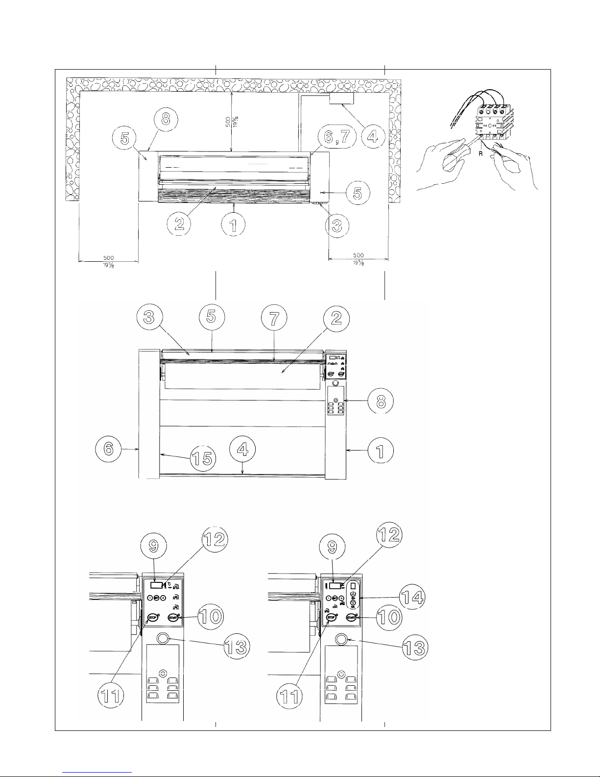
40
Fig. 3
Fig. 2
FIGURE, FIGURES, FIGURES, ABBILDUGEN, FIGURAS
LINEA, LINE, LIGNE,
LINIE, LÍNEA
Fig. 1

41
FIGURE, FIGURES, FIGURES, ABBILDUGEN, FIGURAS
41
Fig. 4
Fig. 6
Fig. 5

MODIFICHE SENZA PREAVVISO, CHANGES WITHOUT NOTICE, MODIFICATIONS SANS PRÉAVIS, ÄNDERUNGEN VORBEHALTEN, MODIFICACIONES SIN PREVIO AVISO
TARGHETTA TECNICA, RATING PLATE, PLAQUETTE
TECHNIQUE, GERÄTESCHILD, PLACA DE CARACTERÍSTICAS
RIVENDITORE, DISTRIBUTOR,
REVENDEUR, VERTRIEB, REVENDEDOR
ASSISTENZA TECNICA, AFTER-SALES SERVICE,
SERVICE APRES-VENTE, KUNDENDIENST,
SERVICIO DE ASISTENCIA TÉCNICA
MODELLO
MODEL
NR. MATR.
SERIAL NR.
ALIM. EL.
EL. POWER
POTENZA TOT.
TOTAL INPUT
PRESSIONE VAPORE
STEAM PRESSURE
ATTENZIONE! E' OBBLIGATORIO IL COLLEGAMENTO A TERRA
CAUTION! THE APPLIANCE MUST BE CONNECTED TO EARTH
 Loading...