

Page 1
Page 2

Limited warranty
Elektron synthesizers are sold with one year full warranty.This warranty covers all malfunctions that may occur from
normal use. Damage caused by careless handling (improper voltage connected, exposure to damp, abuse etc.) is not
covered. The unit can only be returned for repair after agreement from Elektron. Customer covers cost of shipping of
malfunctioning unit from customer to Elektron. Elektron covers shipping from Elektron back to customer. Elektron
agrees to offer spare parts and service for all synthesizer produced by Elektron also after the warranty expires as long
as is possible. The warranty applies to the physical unit and applies also for customers buying units second hand
where the warranty still is valid. The warranty is void without a readable serial number label.
Elektron offers ten days money back guarantee for all synthesizers sold directly by Elektron. A returned unit has to be
in condition "as new". The ten days are counted from arrival of the unit. The refund is transferred as we receive the
returned unit. The customer covers the cost of the return shipping.
FCC compliance statement
This device complies with part 15 of the FCC rules. Operation is subject to the following two conditions: (1) This device
may not cause harmful interference, and (2) this device must accept any interference received, including interference
that may cause undesired operation.
NOTE: This equipment has been tested and found to comply with the limits for a Class B digital device, pursuant to
Part 15 of the FCC Rules. These limits are designed to provide reasonable protection against harmful interference in
a residentpial installation. This equipment generates, uses and can radiate radio frequency energy and, if not installed
and used in accordance with the instructions, may cause harmful interference to radio communications. However,
there is no guarantee that interference will not occur in a particular installation. If this equipment does cause harmful
interference to radio or television reception, which can be determined by turning the equipment off and on, the user
is encouraged to try to correct the interference by one or more of the following measures:
• Reorient or relocate the receiving antenna.
• Increase the separation between the equipment and receiver.
• Connect the equipment into an outlet on a circuit different from that to which the receiver is connected.
• Consult the dealer or an experienced radio/TV technician for help.
European Union regulation compliance statement
This product has been tested to comply with the 2004/108/EC EMC Directive and the 72/23/EC Low Voltage directive.
This symbol indicates that your product must be disposed of properly according to local laws and regulations.
The included switched-mode power supply is CEC Level IV compliant.
The device contains a non rechargable lithium perchlorate battery cell that may need to be recycled separately depending on local environmental laws. If the battery needs replacing, please contact Elektron or a local professional
technician for servicing.
Page 3

INTRODUCTION...........................................................................................................1-1
CONVENTIONS IN THIS MANUAL..................................................................................................... 1-1
THE STORY OF THE MACHINEDRUM .......................................................................1-2
Machinedrum SPS-1 MKII/SPS-1UW MKII MAIN FEATURES............................................................ 1-2
USER INTERFACE AND CONNECTORS....................................................................1-4
FRONT PANEL .................................................................................................................................... 1-4
REAR CONNECTORS ........................................................................................................................ 1-6
RACK MOUNT KIT (ACCESSORY) .................................................................................................... 1-7
RACK MOUNT KIT ASSEMBLY..................................................................................................... 1-7
CONNECTING THE UNIT ................................................................................................................... 1-7
CARE INSTRUCTIONS ....................................................................................................................... 1-7
THE LCD USER INTERFACE ......................................................................................1-9
LAYER EDIT AND WINDOWS ............................................................................................................ 1-9
QUICK START ............................................................................................................1-10
PLAYING AND TWEAKING DRUM SOUNDS................................................................................... 1-10
USING THE TRACK EFFECTS......................................................................................................... 1-10
SELECTING AND PLAYING A PATTERN......................................................................................... 1-10
RECORDING A PATTERN USING GRID RECORDING................................................................... 1-11
SETTING THE ACCENT PATTERN .................................................................................................. 1-11
SETTING THE SWING PATTERN..................................................................................................... 1-11
PATTERN LIVE RECORDING........................................................................................................... 1-12
PARAMETER LOCKS........................................................................................................................ 1-12
THE SOUND SYNTHESIS OF MACHINEDRUM .......................................................1-13
MACHINEDRUM KITS....................................................................................................................... 1-14
LOADING A KIT............................................................................................................................ 1-14
SAVING AND NAMING A KIT ...................................................................................................... 1-15
UNDO KIT..................................................................................................................................... 1-16
COPY KIT ..................................................................................................................................... 1-16
CLEAR KIT ................................................................................................................................... 1-17
KIT ASSEMBLY............................................................................................................................ 1-17
SETTING MUTE AND TRIG RELATIONS OF A KIT.................................................................... 1-18
COPY MACHINE .......................................................................................................................... 1-19
CLEAR MACHINE ........................................................................................................................ 1-20
MACHINE PARAMETER EDITING.................................................................................................... 1-21
THE TRACK EFFECTS ..............................................................................................1-22
AMPLITUDE MODULATOR.......................................................................................................... 1-22
TRACK EQ ................................................................................................................................... 1-23
FILTER.......................................................................................................................................... 1-23
THE SAMPLE RATE REDUCER.................................................................................................. 1-24
THE ROUTING PAGE.................................................................................................1-25
DISTORTION................................................................................................................................ 1-25
VOLUME....................................................................................................................................... 1-25
PAN............................................................................................................................................... 1-26
DELAY SEND ............................................................................................................................... 1-26
REVERB SEND ............................................................................................................................ 1-26
LFO CONTROL ............................................................................................................................ 1-27
THE STEREO MASTER EFFECT SYSTEM .............................................................1-28
THE RHYTHM ECHO DELAY ...................................................................................................... 1-29
THE GATE BOX REVERB............................................................................................................ 1-30
MASTER EQ................................................................................................................................. 1-30
I of VI
Page 4

THE DYNAMIX DYNAMICS PROCESSOR ................................................................................. 1-31
LOW FREQUENCY OSCILLATORS (LFO’s) ............................................................ 1-32
THE PATTERN SEQUENCER...................................................................................1-35
CLASSIC VS EXTENDED ................................................................................................................. 1-35
CLASSIC EDITING ....................................................................................................................... 1-35
EXTENDED EDITING................................................................................................................... 1-35
TEMPO .............................................................................................................................................. 1-36
THE TEMPO SCREEN ................................................................................................................. 1-36
TAP TEMPO ................................................................................................................................. 1-36
EXTERNAL SYNCHRONIZATION ............................................................................................... 1-36
PATTERN MODE............................................................................................................................... 1-37
PATTERN SELECTION ................................................................................................................ 1-37
PATTERN CHAINING................................................................................................................... 1-37
PARAMETER TWEAKING............................................................................................................ 1-37
SCALE SETUP ............................................................................................................................. 1-38
COMPOSING A PATTERN................................................................................................................ 1-39
GRID RECORDING ......................................................................................................................1-39
PATTERN PAGE FUNCTIONALITY ON MKI UNITS.................................................................... 1-39
LIVE RECORDING ....................................................................................................................... 1-39
NOTE COPY................................................................................................................................. 1-40
CLEAR NOTE PARAMETER LOCKS........................................................................................... 1-40
TRACK COPY............................................................................................................................... 1-41
CLEAR TRACK............................................................................................................................. 1-41
TRACK PAGE COPY.................................................................................................................... 1-42
CLEAR TRACK PAGE.................................................................................................................. 1-42
PATTERN COPY .......................................................................................................................... 1-43
CLEAR PATTERN......................................................................................................................... 1-44
TRACK MUTING................................................................................................................................ 1-44
THE TRACK MUTE WINDOW...................................................................................................... 1-44
MINIMISING THE MUTE WINDOW ............................................................................................. 1-45
ACCENT TRACK ............................................................................................................................... 1-45
SWING............................................................................................................................................... 1-46
THE SWING WINDOW................................................................................................................. 1-46
PARAMETER LOCKS........................................................................................................................ 1-47
PARAMETER LOCKS IN GRID RECORDING MODE .................................................................1-47
PARAMETER LOCKS IN LIVE RECORDING MODE .................................................................. 1-48
PARAMETER LOCK SLIDE............................................................................................................... 1-49
SONG MODE..............................................................................................................1-51
LOAD SONG................................................................................................................................. 1-51
PLAYING A SONG........................................................................................................................ 1-52
NAVIGATING A SONG ................................................................................................................. 1-52
SONG EDITING............................................................................................................................ 1-52
SONG ROW OFFSETS AND LENGTHS...................................................................................... 1-54
SONG TRANSPORT .................................................................................................................... 1-54
SONG LOOP ................................................................................................................................ 1-54
SONG JUMP................................................................................................................................. 1-55
SONG HALT ................................................................................................................................. 1-55
SONG MUTE ................................................................................................................................ 1-55
SAVE SONG ................................................................................................................................. 1-56
GLOBAL SETTINGS ..................................................................................................1-57
MIDI ................................................................................................................................................... 1-57
BASE CHANNEL ............................................................................................................................... 1-58
II of VI
Page 5

MAP EDITOR..................................................................................................................................... 1-58
LOCAL CONTROL ............................................................................................................................ 1-59
SYSEX SEND.................................................................................................................................... 1-60
ALL DATA SYSEX SEND ............................................................................................................. 1-61
GLOBAL SYSEX SEND ............................................................................................................... 1-62
SONG + PATTERN (+ KIT) SYSEX SEND................................................................................... 1-62
PATTERN (+ KIT) SYSEX SEND ................................................................................................. 1-62
KIT SYSEX SEND ........................................................................................................................ 1-62
SYSEX RECEIVE ......................................................................................................................... 1-62
GENERAL SYSEX RECEIVE....................................................................................................... 1-63
ORIGINAL PLACE SYSEX RECEIVE .......................................................................................... 1-64
SPECIFIC PLACE SYSEX RECEIVE........................................................................................... 1-64
SYSEX VERIFY............................................................................................................................ 1-65
PROGRAM CHANGE ........................................................................................................................ 1-66
SAMPLE MANAGER (SPS-1UW/SPS-1UW MKII ONLY) ................................................................. 1-67
THE DIFFERENCE BETWEEN ROM AND RAM MACHINES..................................................... 1-68
RAM TO ROM COPY ................................................................................................................... 1-68
GENERAL SAMPLE RECEIVE .................................................................................................... 1-68
SPECIFIC PLACE SAMPLE RECEIVE ........................................................................................ 1-69
ORIGINAL PLACE SAMPLE RECEIVE ....................................................................................... 1-70
SEND SAMPLES.......................................................................................................................... 1-70
ERASE SAMPLES........................................................................................................................ 1-71
ROUTING .......................................................................................................................................... 1-72
TRIG .................................................................................................................................................. 1-73
SYNC................................................................................................................................................. 1-73
TEMPO IN .................................................................................................................................... 1-74
CTRL IN........................................................................................................................................ 1-74
TEMPO OUT ................................................................................................................................ 1-75
CTRL OUT.................................................................................................................................... 1-76
EARLY STARTUP MENU ...........................................................................................1-77
TEST MODE...................................................................................................................................... 1-77
EMPTY RESET.................................................................................................................................. 1-77
FACTORY RESET ............................................................................................................................. 1-77
SOFT RESET .................................................................................................................................... 1-77
MIDI UPGRADE ................................................................................................................................ 1-77
SEND UPGRADE .............................................................................................................................. 1-79
TECHNICAL INFORMATION......................................................................................1-80
SPECIFICATIONS ............................................................................................................................. 1-80
DIFFERENCES BETWEEN THE MKI AND MKII MODELS ......................................1-81
DESIGN ............................................................................................................................................. 1-81
POWER SUPPLY .............................................................................................................................. 1-81
S/N RATIO AND OUTPUTS .............................................................................................................. 1-81
SAMPLER SPECIFICATIONS (UW MODELS ONLY)....................................................................... 1-81
PATTERN LENGTH ........................................................................................................................... 1-81
CREDITS.....................................................................................................................1-82
PRODUCT DESIGN AND DEVELOPMENT...................................................................................... 1-82
ADDITIONAL DESIGN ...................................................................................................................... 1-82
FACTORY DEFAULT SOUND DESIGN ............................................................................................ 1-82
USER’S MANUAL.............................................................................................................................. 1-82
CONTACT INFORMATION .........................................................................................1-82
ELEKTRON SUPPORT ..................................................................................................................... 1-82
III of VI
Page 6

ELEKTRON WEBSITE ...................................................................................................................... 1-82
DELIVERY ADDRESS....................................................................................................................... 1-82
APPENDIX A: MACHINE REFERENCE
TRX......................................................................................................................................................A-1
BASS DRUM “TRX-BD”..................................................................................................................A-1
BASS DRUM “TRX-B2” ..................................................................................................................A-1
SNARE DRUM “TRX-SD” ...............................................................................................................A-1
TOM “TRX-XT”................................................................................................................................A-2
CLAP “TRX-CP”..............................................................................................................................A-2
RIM SHOT “TRX-RS”......................................................................................................................A-2
COW BELL “TRX-CB”.....................................................................................................................A-2
CLOSED HIHAT “TRX-CH”.............................................................................................................A-2
OPEN HIHAT “TRX-OH”.................................................................................................................A-2
CYMBAL “TRX-CY” ........................................................................................................................A-2
MARACAS “TRX-MA” .....................................................................................................................A-2
CLAVES “TRX-CL”..........................................................................................................................A-3
CONGAS “TRX-XC”........................................................................................................................A-3
EFM .....................................................................................................................................................A-4
BASS DRUM “EFM-BD” .................................................................................................................A-4
SNARE DRUM “EFM-SD”...............................................................................................................A-4
TOM “EFM-XT” ...............................................................................................................................A-4
CLAP “EFM-CP” .............................................................................................................................A-4
RIMSHOT “EFM-RS” ......................................................................................................................A-4
COWBELL “EFM-CB” .....................................................................................................................A-4
HIHAT “EFM-HH”............................................................................................................................A-5
CYMBAL “EFM-CY” ........................................................................................................................A-5
E12.......................................................................................................................................................A-6
BASS DRUM “E12-BD”...................................................................................................................A-6
SNARE DRUM “E12-SD”................................................................................................................A-6
HIGH TOM “E12-HT” ......................................................................................................................A-6
LOW TOM “E12-LT” ........................................................................................................................A-6
CLAP “E12-CP”...............................................................................................................................A-6
RIMSHOT “E12-RS” .......................................................................................................................A-6
COW BELL “E12-CB” .....................................................................................................................A-7
CLOSED HIHAT “E12-CH” .............................................................................................................A-7
OPEN HIHAT “E12-OH”..................................................................................................................A-7
RIDE CYMBAL “E12-RC” ...............................................................................................................A-7
CRASH CYMBAL “E12-CC” ...........................................................................................................A-7
BRUSHED SNARE “E12-BR” .........................................................................................................A-7
TAMBOURINE “E12-TA”.................................................................................................................A-8
TRIANGLE “E12-TR” ......................................................................................................................A-8
SHAKER “E12-SH” .........................................................................................................................A-8
BONGO CONGO “E12-BC” ............................................................................................................A-8
P-I ........................................................................................................................................................A-9
BASS DRUM “PI-BD”......................................................................................................................A-9
SNARE DRUM “PI-SD”...................................................................................................................A-9
TOM “PI-XT” ...................................................................................................................................A-9
RIMSHOT “PI-RS” ..........................................................................................................................A-9
METALLICA “PI-ML” .......................................................................................................................A-9
MARACAS “PI-MA”.........................................................................................................................A-9
HI HAT “PI-HH” ...............................................................................................................................A-9
RIDE CYMBAL “PI-RC” ................................................................................................................A-10
CRASH CYMBAL “PI-CC” ............................................................................................................A-10
GND ...................................................................................................................................................A-11
IV of VI
Page 7

SINUS “GND-SN” ......................................................................................................................... A-11
NOISE “GND-NS” ......................................................................................................................... A-11
IMPULSE “GND-IM” ..................................................................................................................... A-11
INP..................................................................................................................................................... A-11
INPUT GATE A/B “INP-GA/B” ...................................................................................................... A-11
INPUT FILTER FOLLOWER A/B “INP-FA/B” ............................................................................... A-11
INPUT ENVELOPE A/B “INP-EA/B” ............................................................................................. A-11
MID ....................................................................................................................................................A-12
CTR ...................................................................................................................................................A-12
CONTROL ALL “CTR-AL” ............................................................................................................A-12
CONTROL 8 PARAMETERS “CTR-8P” .......................................................................................A-13
CONTROL RHYTHM ECHO DELAY “CTR-RE”...........................................................................A-13
CONTROL GATE BOX REVERB “CTR-GB” ................................................................................A-14
CONTROL MASTER EQ “CTR-EQ”.............................................................................................A-14
CONTROL DYNAMIX PROCESSOR “CTR-DX” ..........................................................................A-14
ROM (SPS-1UW ONLY) ....................................................................................................................A-15
ROM MACHINES “ROM-1 - ROM-48”..........................................................................................A-15
RAM (SPS-1UW MKII ONLY) ............................................................................................................A-15
RAM RECORD “RAM-R1 - RAM-R4” ...........................................................................................A-15
RAM PLAY “RAM-P1 - RAM-P4”..................................................................................................A-16
RAM MACHINES TUTORIAL .......................................................................................................A-16
APPENDIX B: MIDI CONTROL REFERENCE
DEFAULT MIDI MAPPINGS ...........................................................................................................B-1
CTRL-CHANGE MAPPINGS..........................................................................................................B-1
APPENDIX C: SYSEX REFERENCE
INDEX
V of VI
Page 8

VI of VI
Page 9

INTRODUCTION
INTRODUCTION
Thank you for choosing the Machinedrum SPS-1 MKII/SPS-1UW MKII, Synthetic Percussion Sequencer. The Machinedrum is a powerful and intuitive tool for creating percussion
sounds and rhythm sequences. The Elektron development team would like to take this
opportunity to thank you for your choice of music creation tool. We hope that you will have
a lot of fun while exploring the vast possibilities of the Machinedrum. To make the most of
the SPS-1 MKII/SPS-1UW MKII, we would recommend you to carefully read the relevant
parts of this manual.
This manual is specifically written for the MKII versions of the Machinedrum family. However, although differences exist between the MKI and MKII models, this manual it is also
usable for MKI models. Please see “DIFFERENCES BETWEEN THE MKI AND MKII
MODELS” on page 81 for more details on exactly what differs between the two models.
CONVENTIONS IN THIS MANUAL
In this manual, we have used certain conventions to indicate input operations using knobs
nd buttons and output from the user interface. These conventions are listed below:
a
Buttons are written in upper case with bold style, and they are enclosed in brackets. For
instance, the button “function” on the main panel is written [FUNCTION].
Menu names, certain modes and operations will be written in upper case. The SYNTHESIS
menu is an example of that.
Messages visible on the screen will be written in upper case with quotation marks. Like
this, “RECEIVING DUMP”.
Parameter abbreviations as they appear on the screen are written in bold style, for example PTCH.
Knobs are written in upper case with bold, italic style. For instance, the knob “level” is written LEVEL.
LED indicators like the record light are written <RECORD>.
The following symbols are used throughout the manual:
This symbol indicates information that you need to pay attention to.
This symbol indicates a tip that might make it easier interacting with the Machinedrum.
This symbol is not used, but it shows a nice ear.
1
Page 10

THE STORY OF THE MACHINEDRUM
THE STORY OF THE MACHINEDRUM
The Machinedrum SPS-1 MKII/SPS-1UW MKII is a music instrument that presents new
methods for music synthesis and creation. It also traces its heritage to classic drum
machines.
The drum machine concept is more than 30 years old. Around the same time that Bob
Moog released his first commercial synthesizer for keyboard players, the first consumer
drum machines were also made available. Although primitive in design with only pre-programmed patterns to offer, they laid the foundation for a new area of electronically aided
music and sound creation.
What followed has formed a good part of the percussive basis for modern music. The drum
machines from Roland (the TR-series), Linn and Simmons are legendary and highly
regarded for their individual synthetic sound. The analogue drum machines were actually
advanced synthesizers, specially designed for creating a specific percussive sound. Today
respect is gained not by recreating the sound of an acoustic drum, but by adding to the
tonal palette of percussion. The method of “grid programming” has also offered a creative
approach to forming rhythms.
Percussion synthesis was a neglected area for many years. Straight static samples can
never replace the full possibilities of a powerful drum synthesizer / sequencer. With the
Machinedrum, we have incorporated the best ideas from the classic drum machines, using
specially designed “machines” for many types of percussion, combined with new rhythm
composing possibilities to make the SPS-1 MKII/SPS-1UW MKII the state of the art drum
synthesizer and sequencer.
For the sample enabled Machinedrum, the Machinedrum SPS-1UW MKII, where “UW” is
short for “UserWave”, inspiration was drawn from the 12-bit samplers of the 1980’s, for
example the EMU SP-1200. The sound from these instruments were often very characteristic and had a punch and grit that can be hard to obtain today. Combining samples with the
ease of use and flexibility that the Machinedrum environment offers will vastly expand the
sound shaping possibilities.
Not only getting inspiration from the past, the concept of the SPS-1UW MKII also makes it
possible to explore new sonic territories as it contains real time sampling features. All this
makes the Machinedrum UserWave an ideal companion for both forward-thinking DJ’s and
beat composers looking for a unique sound.
Machinedrum SPS-1 MKII/SPS-1UW MKII MAIN FEATURES
The SPS-1 MKII/SPS-1UW MKII is built from three parts - the percussion synthesizer, the
ffect system and the percussion sequencer.
e
The synthesizer holds 16 drum generating synthesizers - machines - simultaneously. Each
of the machines is designed for creating a specific drum sound, such as bass drum or
claves, from a set of parameters. The machines can belong to a varied set of MD-synths,
where every MD-synth have a different sound character.
The effect system consists of the TRACK EFFECT system and the STEREO MASTER
EFFECT System. The TRACK EFFECT system supplies Amplitude Modulation, 1-band
EQ, Resonant lo/band/hi-pass filter, Sample Rate Reduction and Distortion tied to each
2
Page 11

THE STORY OF THE MACHINEDRUM
audio track. These effects can be used tightly together with the machines to form the
sound.
The STEREO MASTER EFFECT system consists of a delay, a reverb, an EQ and a
dynamics compressor. These effects operate on the mixed main output signal.
• SPS-1 MKII/SPS-1UW MKII features the MD-synths TRX, EFM, E12, PI and GND
t
hat generate percussive sounds from different theories and practices. The SPS-
1UW MKII adds the sample handling ROM and RAM machines.
• The MD-synths offer specialised machines. Each machine is designed for creating
specific drum sound, such as bass drum or claves.
a
• A wide variety of special machines are available. These allow creative usage of
the external inputs and extensive control options.
• The machines are arranged in kits together with settings for the track and master
effects, giving a total of 16 fully user controlled real time synthesized percussion
sounds.
• Each machine has up to eight parameters, which can be tweaked in real time by
the user.
• A machine used in a kit is assigned to one of the 16 tracks controlled by the
sequencer.
• Each track has its own track effect, consisting of amplitude Modulation, 1-band
EQ, resonant lo/band/hi-pass filter, sample rate reduction and distortion.
• The sequencer has full control over the machines, as well as the Track Effects.
• The STEREO MASTER EFFECT system consists of the RHYTHM ECHO, the GATE
BOX REVERB, the MASTER EQ and the DYNAMIX compressor. Each track has
separate send routing for the RHYTHM ECHO and the GATE BOX reverb.
• In addition to the MD-synths, the SPS-1 MKII/SPS-1UW MKII can also function as a
very competent MIDI sequencer by using machines especially designed for controlling external MIDI instruments.
• The SPS-1UW MKII can contain up to 2,5 MB of samples, divided into 48 sample
lots.
s
Machinedrum SPS-1/SPS-1 UW/SPS-1 MKII/SPS-1UW MKII USER’S MANUAL for operating system version
1.52. This manual (rev I) is copyright © 2001-2009 Elektron Music Machines MAV AB. All reproduction without
written authorization is strictly prohibited. The information in this manual may change without notice. Elektron’s
product names, logotypes, titles, words or phrases may be registered and protected by Swedish and international
law. All other brand or product names are trademarks or registered trademarks of their respective holders.
3
Page 12
USER INTERFACE AND CONNECTORS
'
&*
&."'&
&)&'"&(
&,
&-
'*
')
,"&%
)
+
(
&
*
''
'(
&&
3 HT 4 MT 6 CP 7 RS 8 CB 10 OH 11 RC 12 CC 14 M2 15 M3 16 M4
1/64
1:4 2:4 3:4 4:4
5 LT 9 CH 13 M1
SONG SETUPGLOBAL
USER INTERFACE AND CONNECTORS
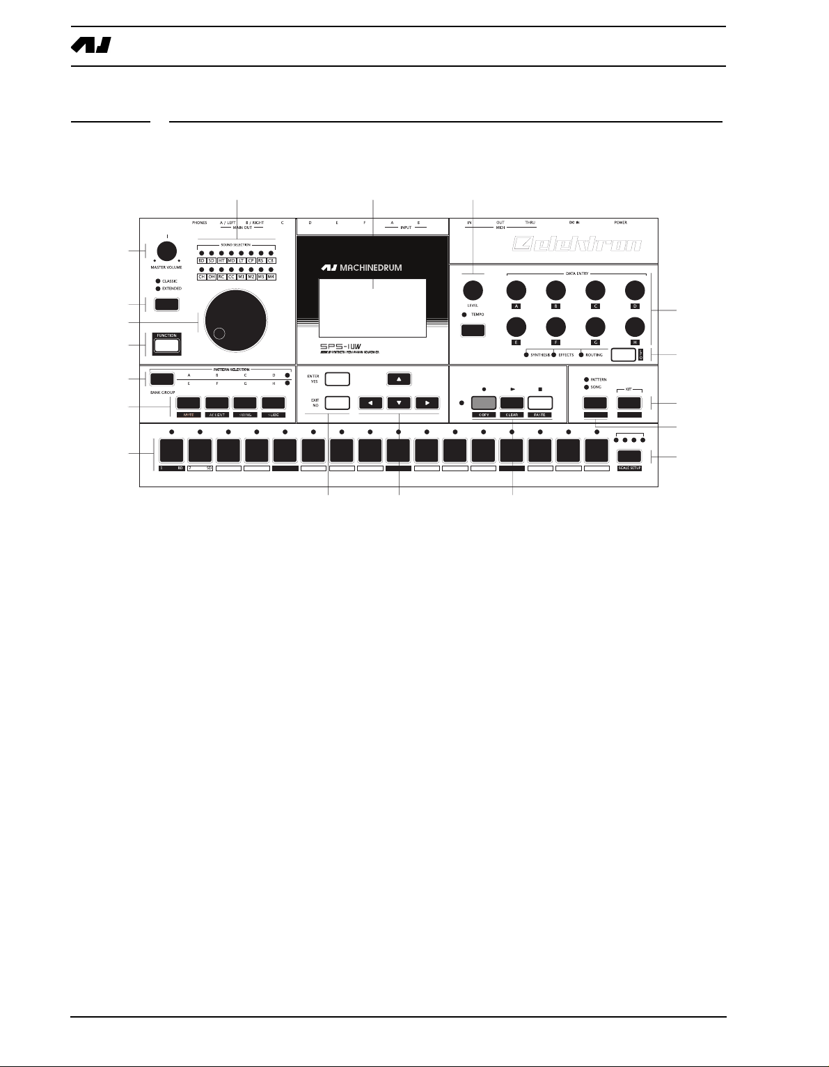
FRONT PANEL
The Machinedrum SPS-1 MKII/SPS-1UW MKII front panel:
. Master volume control. Sets the volume for the main output and headphone jack.
1
2. The <SOUND SELECTION> LEDs. Used for indicating the current track in focus and for
showing which tracks are triggered.
3. [CLASSIC/EXTENDED] m
ode change key. Changes current editing mode between
CLASSIC and EXTENDED.
4. SOUND SELECTION wheel. Selects tracks and changes values during editing. You can
also select tracks by holding the [FUNCTION] key while pressing the corresponding
[TRIG] key.
5. [FUNCTION] key. Press and hold it for accessing the secondary function of another key.
6. [BANK] key. Used for switching between bank group A to D and E to H.
7. [A/E] key. Hold this key while pressing one of the [TRIG] keys to select a pattern in
either the A or the E bank, depending on which bank group is selected. The secondary
function is track muting.
8. [B/F] key. Hold this key while pressing one of the [TRIG] keys to select a pattern in
either the B or the F bank, depending on which bank group is selected. The secondary
function is accent pattern editing.
9. [C/G] key. Hold this key while pressing one of the [TRIG] keys to select a pattern in
either the C or the G bank, depending on which bank group is selected. The secondary
function is the pattern swing settings.
10.[D/H] key. Hold this key while pressing one of the [TRIG] keys to select a pattern in
either the D or the H bank, depending on which bank group is selected. The secondary
function is slide pattern editing.
11.The LCD graphical interface.
12.[ENTER/YES] k
ey. Used for entering sub-menus and for confirming choices.
4
Page 13

USER INTERFACE AND CONNECTORS
13.[EXIT/NO] key. Used for exiting the current menu and for deselecting options.
1
4.The arrow keys. Used for menu navigation. They are called [UP], [DOWN], [LEFT] and
[RIGHT].
15.LEVEL knob. Sets the overall volume level of the track in focus.
16.[TEMPO] key. Brings up the tempo menu. The current tempo is always indicated by the
speed the <TEMPO> LED is flashing.
17.DATA ENTRY knobs. Used for tweaking parameters for the machines and effects.
18.[SYNTHESIS/EFFECTS/ROUTING] toggle key. Switches the editing focus for the
DATA ENTRY knobs. The active page is indicated by the <SYNTHESIS>, <EFFECTS>
and <ROUTING> LEDs. The secondary function is calling the LFO edit menu.
19.[RECORD] ke
y. Toggles grid edit mode on/off. Starts live recording if held while pressing
[PLAY]. In GRID RECORDING mode, the <RECORD> LED gives a steady light, while
in live recording it flashes. The secondary function is COPY.
20.[PLAY] key. Initiates playback of a pattern or song. Pressing [PLAY] a second time
pauses playback. The secondary function is the CLEAR operation.
21.[STOP] key. Stops the playback of a pattern or song. The secondary function is PASTE.
• The copy, clear and paste functions are tied to different data depending on the
context where they are used. Their use will be described in their respective parts
of this manual.
22.[PATTERN/SONG] key. Switches between pattern and song sequencer mode. The cur-
rent sequencer mode is indicated by the <PATTERN> and <SONG> LEDs. The secondary function is calling the GLOBAL EDIT menu.
23.[KIT] key. Opens the KIT menu. The secondary function is opening the SONG menu.
24.[TRIG] keys 1 to 16. Used for direct trigging of machine per track, and for placing notes
in th GRID RECORDING and LIVE RECORDING modes. Also used for choosing pattern, if pressed while holding [A-H] keys. They are also used for selecting track when
pressed while holding [FUNCTION]. Above each [TRIG] key is a <TRIG> LED.
25.[SCALE SETUP] ke
ent pattern pages, if the scale length is longer than 16 steps. Above the [SCALE
SETUP] key the four <PATTERN PAGE> LEDs are placed. If for example 64 steps is
used in a pattern, all four LEDs will be lit. The LEDs are used for indicating which page
of the pattern currently being played or edited. Note that MKI units can have a maximum of 32 steps per pattern.
y. Switches the editing focus of the [TRIG] keys between the differ-
For scale lengths up to 16 steps, the <1:4> LED will stay lit and pressing [SCALE
SETUP] will have no effect. The secondary function of the [SCALE SETUP] key is
calling the SCALE SETUP menu.
5
Page 14
USER INTERFACE AND CONNECTORS
&
HEH"&$HEH"&JL
'&)+",&'"&(-"&&("*
&'&)+",&'"&(-"&&("*
HEH"&B@>>$HEH"&JLB@>>
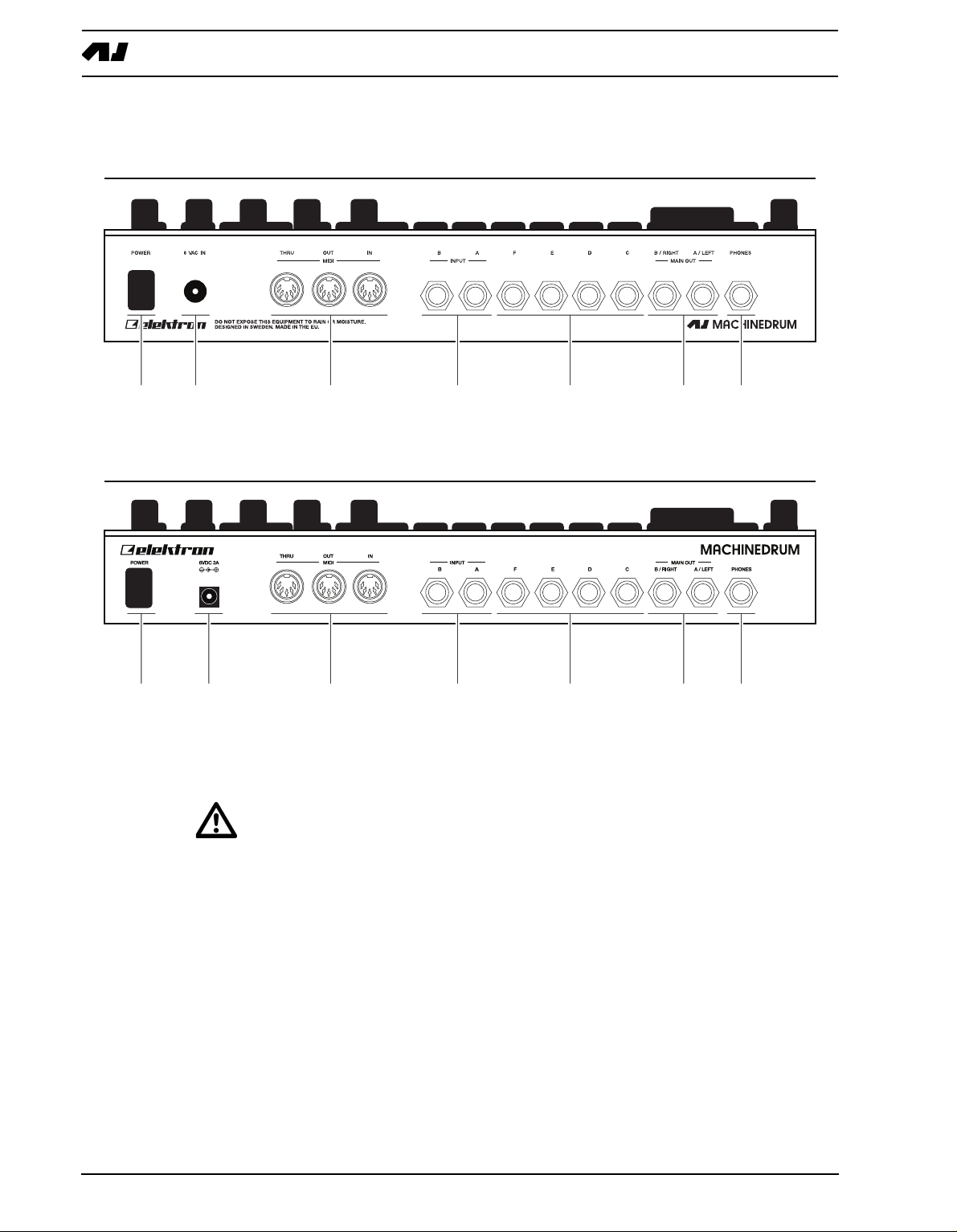
REAR CONNECTORS
The Machinedrum SPS-1 MKII/SPS-1UW MKII rear connectors:
. Power on/off switch.
1
2. 6V DC power in.
• Caution! Use only an Elektron-approved power supply with your Machinedrum
SPS-1 MKII/SPS-1UW MKII. A power supply is included with all MKII models. It
can be used all over the globe without the need of voltage converters using an
appropriate power cord. Using the wrong type of adapter may damage your unit.
Damage caused by the use of incorrect power supply is not covered by warranty.
Please see “TECHNICAL INFORMATION” on page 80 for details about the MKII
power supply.
• Note that the MKI models require a different power supply compared to the MKII
models. Please see “DIFFERENCES BETWEEN THE MKI AND MKII MODELS” on
page 81 for details about the power supply to be used with the MKI models.
3. MIDI Thru.
4. MIDI Out.
5. MIDI In.
6. Input B.
6
Page 15

USER INTERFACE AND CONNECTORS
7. Input A.
8. Individual output F.
9. Individual output E.
10. Individual output D.
11. Individual output C.
12. Main out right / Individual output B.
13. Main out left / Individual output A.
14. Stereo headphones output.
RACK MOUNT KIT (ACCESSORY)
The Machinedrum SPS-1 MKII/SPS-1UW MKII can be rack mounted in a standard 19”
rack, using the Machinedrum rack mount kit which is ordered separately. When rack
mounted, the unit occupies four standard height units plus whatever additional space is
needed to accommodate cables plugged into the unit at the back.
RACK MOUNT KIT ASSEMBLY
Make sure that you have a Philips screwdriver which is in good condition, and which is the
right size. Use the included M3x6mm size screws to secure the rack mount consoles on
each side of the Machinedrum. Make sure that all screws are fastened for secure operation
of the unit.
CONNECTING THE UNIT
Before you start connecting the Machinedrum to other units, make sure that everything is
switched off.
1. Insert the supplied DC adapter into the wall socket, and connect the small plug into the
rear of the Machinedrum unit.
2. Connect the main out L/R from the Machinedrum to your
3. If MIDI control is desired, connect MIDI OUT from the Machinedrum to the device that
mixer or amplifier.
you wish to send data to. Connect the MIDI IN to the device that you wish to receive data
from. The MIDI THRU port “echoes” the data arriving at the MIDI IN port, so it can be
used for chaining MIDI units together.
4. Switch on all units.
CARE INSTRUCTIONS
To ensure many years of trouble free operation, please follow the advice below:
• Never use any aggressive cleaners on the casing or the LCD overlay. Remove
dust, dirt and fingerprints with a soft dry cloth. More persistent dirt can be
removed with a slightly damp cloth using only water.
• Never use sharp objects near the display to avoid scratches or damage. Also
avoid applying any pressure to the display itself.
• When transporting the Machinedrum, try to use the box and padding the Machine-
drum originally shipped with, or comparable packaging.
• Make sure that you place the unit on a stable surface before use. If you mount the
unit in a rack, be sure to tighten all four screws in the rack mount holes.
• The memory used for storing patches and kits is powered by a battery inside the
nit. It will hold data at least 6 years before needing replacement. If the battery
u
7
Page 16

USER INTERFACE AND CONNECTORS
needs replacement, the “BATTERY LOW” message will appear in the display. Contact Elektron support or your nearest repair center.
• Turn off the machine when it is not in use.
8
Page 17
THE LCD USER INTERFACE
THE LCD USER INTERFACE
The center of Machinedrum SPS-1 MKII/SPS-1UW MKII editing is the LCD display. The
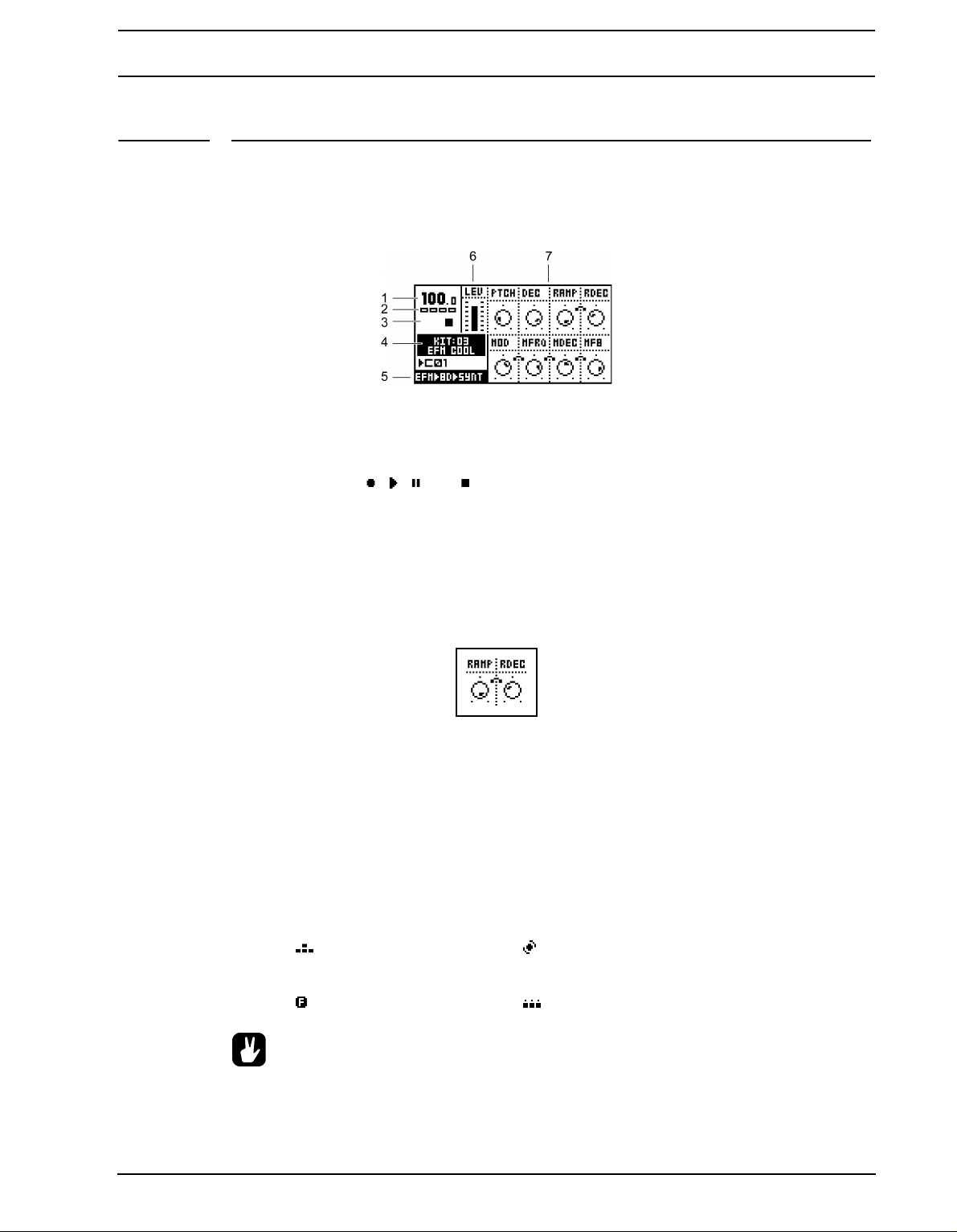
main interface screen is shown below:
1. The current tempo displayed with one decimal.
2. Four boxes showing the playback position in the patte
3. The playback/recording status shown by the standard “record”, “play”, “pause” and
“stop” symbols; , , and .
4. Name and number of the current kit.
5. Specification of the MD-synth, machine and current data entry focus.
6. Level bar showing the overall volume level of the machine on the active track.
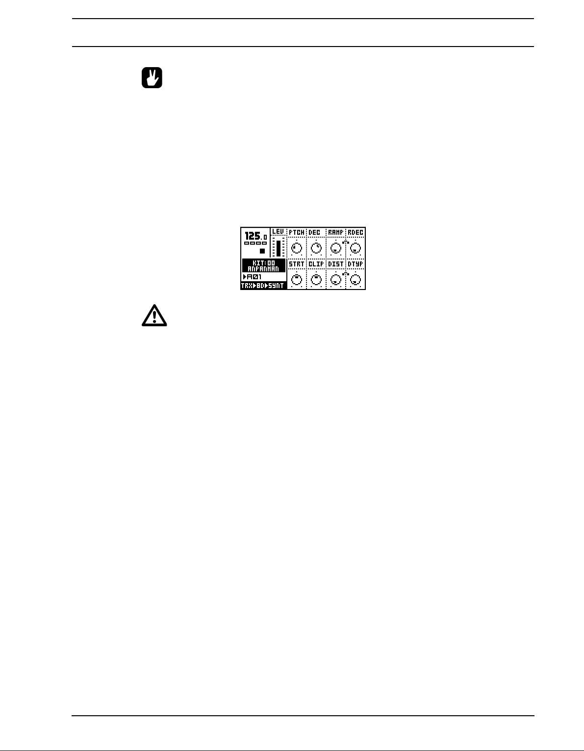
7. Up to eight control data entry values. They show what the DATA ENTRY knobs control
and also indicate the current data entry values. When two parameters depend on each
other in some way, they will have a small “clip” between them as shown below:
rn page.
LAYER EDIT AND WINDOWS
When a function which puts a window on top of the main interface screen is opened, the
unction of certain buttons and/or knobs will change. The buttons that are not used or
f
blocked can still be used to control the layer underneath. For example, when you have
called the tempo function it will make use of the SOUND SELECTION wheel, but you can
still use the DATA ENTRY knobs to control the track in focus. When a window has func-
tions mapped to such interface controls, help is provided at the bottom of the window in the
form of icons representing these controls. The icons are:
The arrow buttons The SOUND SELECTION wheel
The [FUNCTION] key The [TRIG] keys
• All windows can be closed using the [EXIT/NO] key.
9
Page 18

QUICK START
QUICK START
This quick start will guide you through some of the basic operations to allow you to start
using the SPS-1 MKII/SPS-1UW MKII right away. First connect it as described in section
“CONNECTING THE UNIT”, on page 7.
PLAYING AND TWEAKING DRUM SOUNDS
ress the [KIT] key.
1. P
2. Select the LOAD KIT icon in the menu and press [ENTER/YES]. You will now be pre-
sented with a list where you can select a kit name using the [UP] and [DOWN] keys.
3. Press [ENTER/YES] to load the kit. Exit the menu by pressing [EXIT/NO]
4. Now press any of the 16 [TRIG] keys to play the corresponding drum assigned to that
track. You will notice that the drum select LEDs in the upper left corner will light up
accordingly.
5. Turn the SOUND SELECTION wheel so that the <BD> LED is lit. <BD> is now the
“active track”, and every parameter that is being edited will be directed to the bass drum
track.
6. Make sure that the <SYNTHESIS> LED is lit by pressing the toggle key [SYNTHESIS/
EFFECTS/ROUTING].
7. Now, turn any of the DATA ENTRY knobs to tweak the corresponding bass drum
machine specific parameter. You can trigger the sound by pressing the first [TRIG] key
while you are turning the DATA ENTRY knob A to hear the pitch change.
• Instead of using the SOUND SELECTION wheel to choose the active track you can
hold the [FUNCTION] key while pressing the corresponding [TRIG] key.
• The DA
TA ENTRY knobs have accelerated editing when pressed. By default, the
knobs increase/decrease in steps of +1/-1. When pressed, the step length is
higher, allowing quicker adjustments.
USING THE TRACK EFFECTS
1. Press the [SYNTHESIS/EFFECTS/ROUTING] key until the <EFFECTS> LED is lit.
2. You can now edit the track effect parameters for the active track by turning the DATA
ENTRY knobs.
SELECTING AND PLAYING A PATTERN
1. Make sure you have loaded a kit. See the previous section for details on this.
2. Press the [CLASSIC/EXTENDED] key until the <CLASSIC> LED is lit. You are now in
CLASSIC mode. The difference between CLASSIC and EXTENDED mode is explained
in more detail on page 35.
3. Check the [PATTERN/SONG] key so that the <PATTERN> LED is lit.
4. Press the [BANK GROUP] key to select between banks A to D or E to H. Select pattern
bank A to D for this demonstration.
10
Page 19

QUICK START
5. To select pattern A01, press and hold the pattern sel
ection key [A/E] and then the
[TRIG] key 1. You can see the currently selected pattern in the lower left corner of the
display.
6. To play this pattern, simply press the [PLAY] key. The pattern will start playing and will
loop once it reaches the end. Pressing the [PLAY] key while playing pauses the playback. Holding the [STOP] key and pressing [PLAY] will immediately restart the playback
from the beginning. The amount of <SCALE> LEDs lit indicated the number of pages the
pattern consists of. For example, if two <SCALE> LEDs are lit, then the pattern consists
of two pages.
7. To change pattern during playback, simply select a pa
ttern the same way as in step 4.
The display will show the selected pattern beside the current one, but with an arrow
pointing towards it. This indicates that once the current pattern has come to its end, the
selected pattern will begin to play.
8. To stop the playback of the pattern, press the [STOP] key.
• There might be occasions when the Machinedrum keeps making noise after you
press the [STOP] button. This situation can especially occur when using samples
with an infinite decay in the Machinedrum UserWave. In order to force all the
tracks to go quiet, quickly press the [STOP] button twice.
• The pattern page currently playing is indicated by the flashing of the <PATTERN
PAGE> LED.
RECORDING A PATTERN USING GRID RECORDING
1. You can input notes into a pattern in the sequencer, both while it is playing or while it is
currently stopped. Press the [RECORD] key to start grid recording. The <RECORD>
LED will be lit the whole time during the process.
2. Select the active track using the SO
3. Press the [TRIG] keys to insert 16th notes where you wish to have the machine trig-
UND SELECTION wheel.
gered. Pressing the same [TRIG] key once more removes the note.
4. To edit other tracks, change the active track using the SOUND SELECTION wheel.
SETTING THE ACCENT PATTERN
1. Hold [FUNCTION] and press key [B/F] to access the ACCENT screen.
2. On this screen you can set the accent level for all of the accent trigs. Use the SOUND
SELECTION wheel to set the level.
3. The accent pattern is shown on all <TRIG> LEDs above the [TRIG] keys as long as you
are in the accent screen. To accent a note, simply select it by pressing the [TRIG] key.
To remove the accent, press the same key again.
SETTING THE SWING PATTERN
1. Hold [FUNCTION] and press key [C/G] to access the swing screen.
2. On this screen you can set the amount of swing on notes selected by the swing pattern.
Use the SOUND SELECTION wheel to set the level. A level of approximately 65%
should allow you to hear the effect.
3. The swing pattern is shown on all <TRIG> LEDs above t
swing screen is active. The default swing pattern affects every other note, starting with
he [TRIG] keys as long as the
11
Page 20

QUICK START
the second. The swing pattern can be changed using the [TRIG] keys, but for normal
rhythm styles the default pattern is better left as it is.
PATTERN LIVE RECORDING
1. The LIVE RECORDING mode of a pattern allows you to play the sounds in the kit while
the pattern is playing. To start this mode, hold [RECORD] and then press [PLAY].
2. You can now “play” all the machines in the kit directly on the [TRIG] keys. All played
notes will be quantised to 16th notes, and you will be able to hear them the next time the
pattern starts all over.
3. The pattern will loop until you press the [S
TOP] key.
PARAMETER LOCKS
1. Press the [CLASSIC/EXTENDED] key until the <EXTENDED> LED is lit. You are now in
extended mode. The difference between CLASSSIC and EXTENDED mode will be
explained on page 35.
2. Now it is possible to lock parameters to a specific note in the pattern. In GRID RECORD-
ING mode, hold a [TRIG] key and then tweak a parameter. The parameter adjusted will
be inverted on the LCD screen to indicate that it now is locked to the value you have set.
The corresponding <TRIG> LED will flash rapidly to indicate that a parameter is locked
for that step.
3. In LIVE RECORDING mode, you can lock parameters by tweaking the knobs while
recording.
4. Parameters can be locked for several tracks simultaneously. To lock parameters for a
new track, just repeat the sequence from step 2 above.
5. To remove a lock, enter grid edit mode and press the [TRIG] key on the locked note
twice. This removes the lock and restores the note to be triggered. You can also hold the
[TRIG] key while clicking the DATA ENTRY knob corresponding to locked parameter.
You will see that the inversion disappears and that the parameter lock is removed.
12
Page 21
THE SOUND SYNTHESIS OF MACHINEDRUM
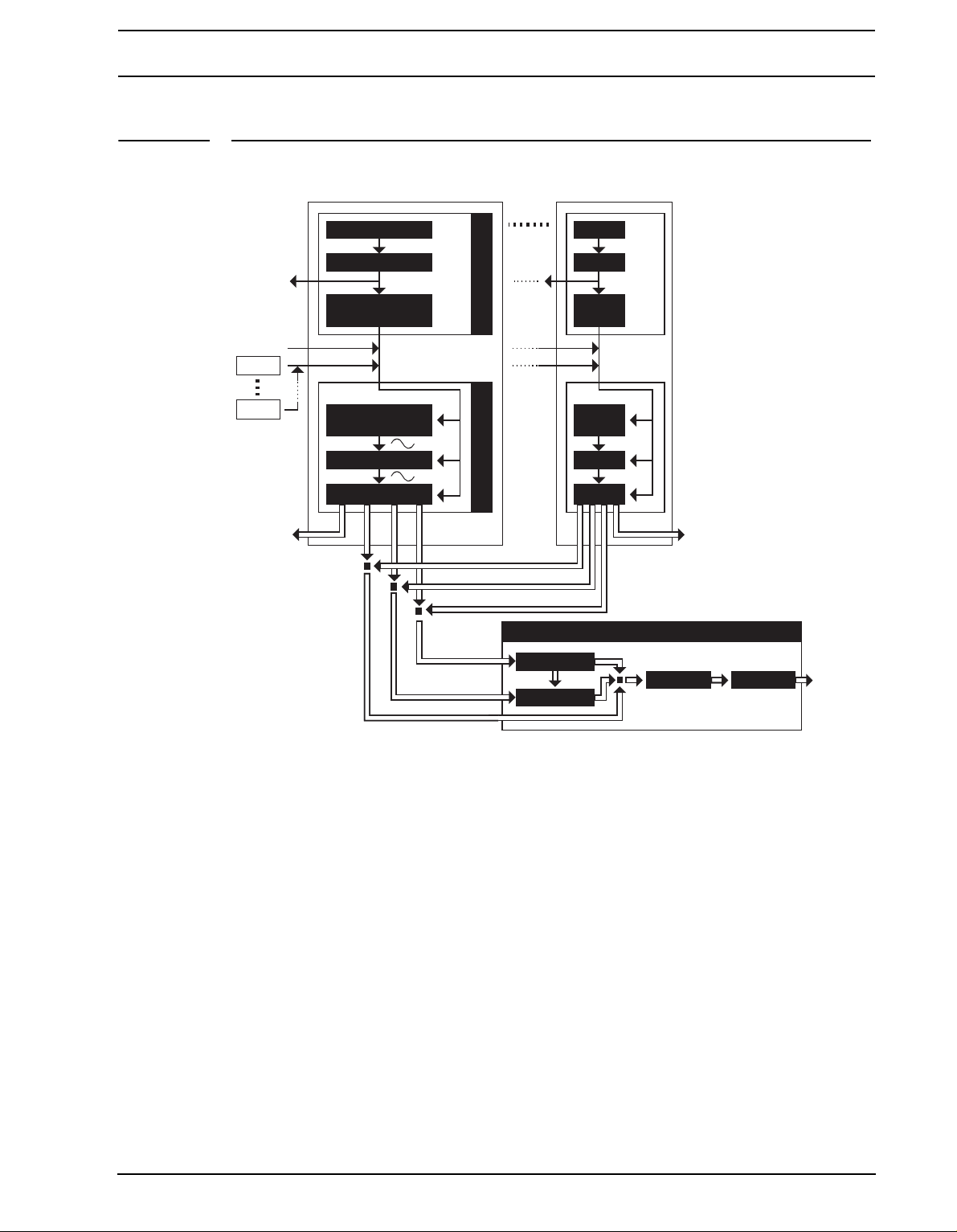
Stereo Master Effects System
Track 01
Step Seq
Accent Swing
Parameter Locks
& Slides
MIDI OUT
MD Pattern Sequencer
MD Machine
Synthesis
Track FX
Dynamix EQ
Routing
Synthesis
MIDI IN
OUT A—F OUT A—F
LFO 1
LFO 16
Track 16
MAIN MIX
Gate Box
Rhythm Echo
THE SOUND SYNTHESIS OF MACHINEDRUM
The basic sound generating unit in the Machinedrum is called a machine. Each machine is
designed for generating a specific drum sound such as bass drum, snare or claves. However, this does not mean that you only have to use it for generating the sound indicated by
its name. The flexible synthesis and effects system can transform a sound completely,
allowing you to come up with unique percussion sounds.
The machines are grouped in MD-synths. You could see it as if the machines in an MDsynth belong to the same family. In the EFM family for example, there are a total of 8
machines for bass drum, snare drum, closed hi-hat etc. Despite the fact that each machine
is based on the family synthesis, each machine has a unique synthesis parameter set. The
parameters have been carefully selected to give you the best sound shaping possibilities
for that particular machine.
The MD-synths and their machines are covered in “Appendix A: MACHINE REFERENCE“.
Each of the 16 tracks can have any machine assigned to it. The assignment of machines
and their parameter settings are collected in so called “kits”. Editing the kits is discussed in
section “KIT ASSEMBLY”, on page 17.
13
Page 22
THE SOUND SYNTHESIS OF MACHINEDRUM
Every track has its own dedicated effect module, called the TRACK EFFECT system. Each
track effect delivers hi/lo/band-pass resonant 24dB filter, amplitude modulation, 1-band eq
and sample rate reduction. The settings of effects are saved in the kit as well. The TRACK
EFFECT system is explained in section “THE TRACK EFFECTS”, on page 22.
The ROUTING page controls pan, delay send, reverb send, output distortion and volume.
The routing options are discussed in section “THE ROUTING PAGE”, on page 25.
The SPS-1 MKII/SPS-1UW MKII offers 16 assignable Low Frequency Oscillators (LFO’s)
that you can connect to any synthesis parameter, track effect or routing parameter. More
about the LFO’s can be found in section “LOW FREQUENCY OSCILLATORS (LFO’s)”, on
page 32.
The STEREO MASTER EFFECT system containing delay, reverb, EQ and compression
add further to the sound shaping possibilities of the Machinedrum. Read more about the
“THE STEREO MASTER EFFECT SYSTEM” on page 28.
MACHINEDRUM KITS
Machinedrum kits hold the information specified below:
• The machine selected for each of the 16 tracks
• Parameter settings for the 16 machines
• Parameter settings for the TRACK EFFECT system
• Parameter settings for routings to the STEREO MASTER EFFECT system.
• Parameter settings for the STEREO MASTER EFFECT system
• The kit name
ll kits are battery backed and user definable. A total of 64 user kits can be stored in mem-
A
ory. When in EXTENDED mode, kits are connected to patterns. Selecting a new pattern will
then automatically load the associated kit. In CLASSIC mode, kits and patterns are not
linked. Read more about this in the chapter “CLASSIC VS EXTENDED” on page 35.
• You can either assemble a kit from scratch or modify an existing one and then
save it to a new position. Building your kit from an existing one is often quicker.
LOADING A KIT
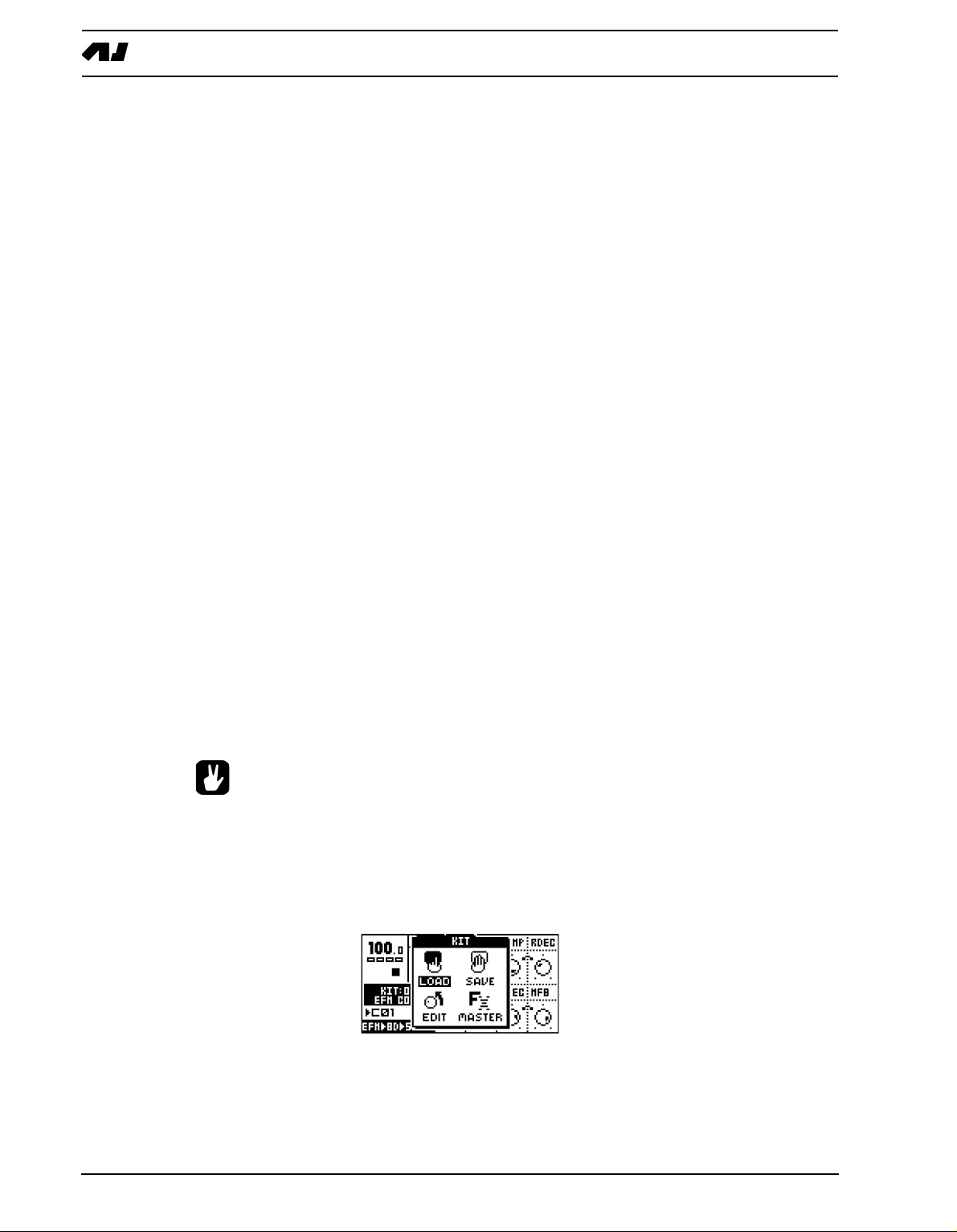
1. Open the KIT window by pressing the [KIT] key
2. Use the arrow keys to move to the LOAD icon. Press [ENTER/YES] to open the LOAD
KIT menu.
14
Page 23
THE SOUND SYNTHESIS OF MACHINEDRUM
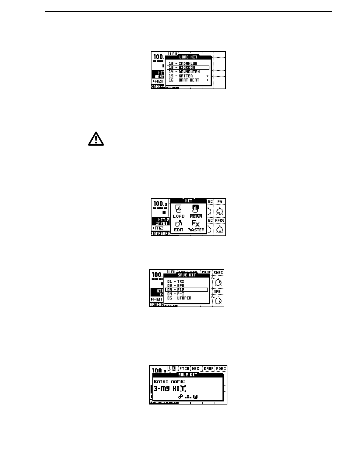
3. The screen presents a list of the kits stored in memo
ry. Use the [UP] and [DOWN] keys
to choose among the 64 kit slots. Press [ENTER/YES] to load the kit of your choice.
If you want to exit without loading a kit, press [EXIT/NO].
• Kits that are not associated with any pattern are distinguished by a little star after
the kit name.
SAVING AND NAMING A KIT
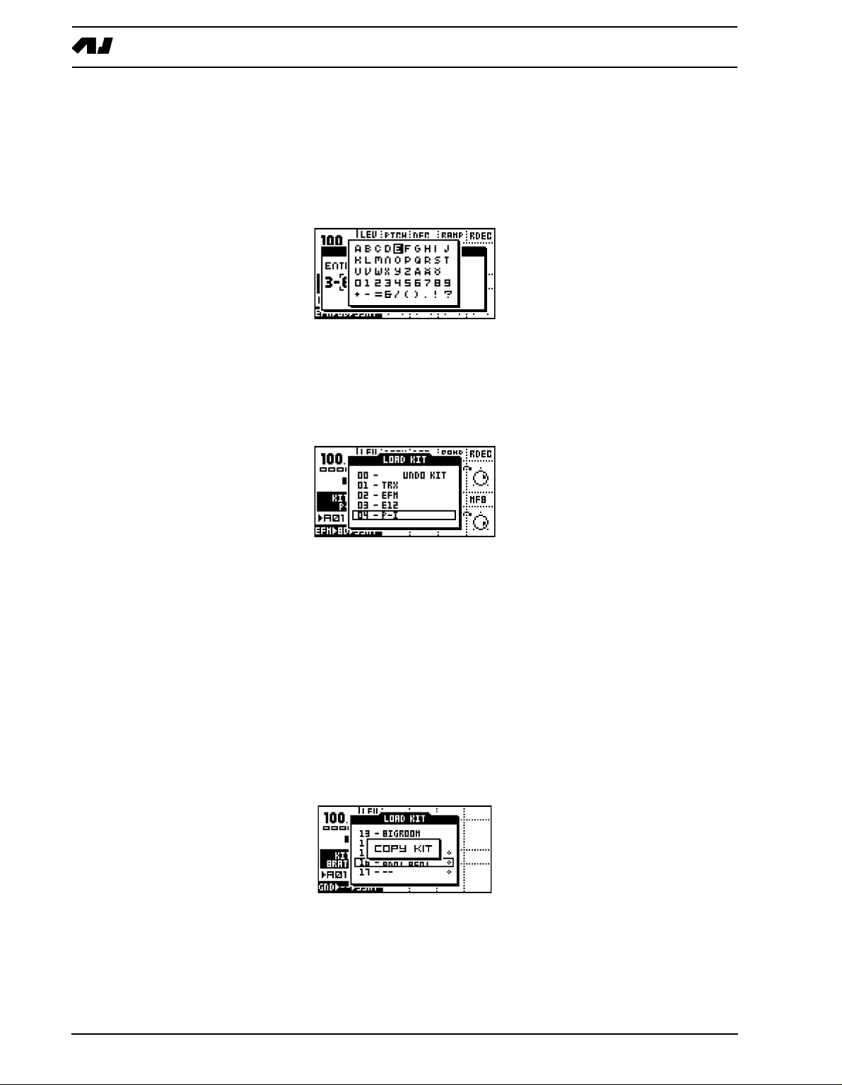
1. Open the KIT window by pressing the [KIT] key.
2. Use the arrow keys to move to the SAVE icon. Press [ENTER/YES] to open the SAVE
KIT menu.
3. The screen presents a list of the kits stored in memo
ry. Use the [UP] and [DOWN] keys
to choose among the 64 kit slots. Press [ENTER/YES] to select the slot where you want
to save your kit.
4. The window opening will allow you to name the kit:
15
Page 24
THE SOUND SYNTHESIS OF MACHINEDRUM
Use the SOUND SELECTION wheel or the [UP] and [DOWN] keys to cycle through the
letters. The [LEFT] and [RIGHT] keys move the cursor backwards and forwards on the
line.
5. Pressing the [FUNCTION] key gives access to the “high score” selection method, in
which you see all characters at the same time. Keep the [FUNCTION] key held while
navigating using the [LEFT], [RIGHT], [UP] and [DOWN] buttons. Release the [FUNC-
TION] key, when you have found the right letter.
6. When the kit naming procedure is completed, press [E
7. If you want to exit without saving the kit, press [EXIT/NO].
UNDO KIT
NTER/YES] to save it.
There is a special kit in the first position of the kit list called the “UNDO KIT”.
When you have made unsaved changes to a kit and a new one is loaded, the unsaved old
kit will be stored in the UNDO KIT position. When saving a kit over an occupied position in
the kit list, the overwritten kit will also be saved in the UNDO KIT.
You can load the UNDO KIT to restore your most recent unintentionally lost kit. This can
often be useful in EXTENDED mode, where a pattern change automatically can change
kits. When you have needed to restore your kit using the UNDO kit, don’t forget to save it.
COPY KIT
When in the SAVE KIT or LOAD KIT menus you can copy a
nd paste kits.
16
When you are in either the SAVE KIT or LOAD KIT menus, select the kit you want to copy,
hold down the [FUNCTION] key and press the [RECORD] button. A message saying
“COPY KIT” appears.
8. Use the [UP] and [DOWN] keys to scroll to the slot you want to copy the kit to.
Page 25
THE SOUND SYNTHESIS OF MACHINEDRUM
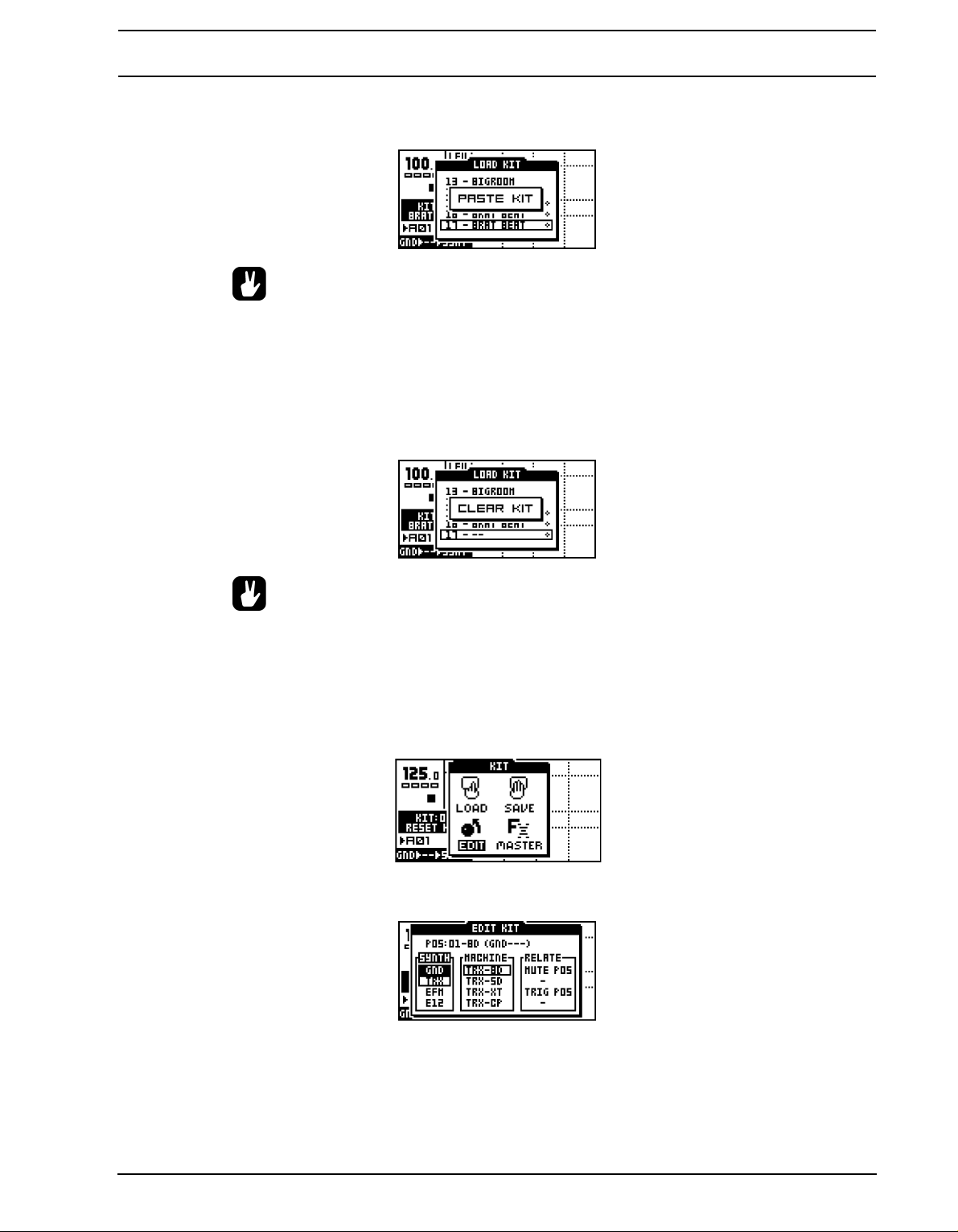
9. To paste the kit into the slot, hold [F
UNCTION] and press the [STOP] button. The mes-
sage “PASTE KIT” appears.
• If you want to undo the action, press the [FUNCTION] + [STOP] buttons again. The
message saying “UNDO KIT” indicates that the paste operation has been undone.
CLEAR KIT
You can also clear kits while in the SAVE or LOAD KIT menus.
1. Select the kit you want to clear, hold down the [FUNCTION] key and press the [PLAY]
button. A message saying “CLEAR KIT” appears.
• It is also possible to undo this operation. To undo the action, hold the function
[FUNCTION] button and press the [PLAY] button. The message saying “UNDO
KIT” indicates that the clear operation has been undone.
KIT ASSEMBLY
To assemble a kit, you need to select and assign your
the KIT window by pressing the [KIT] key.
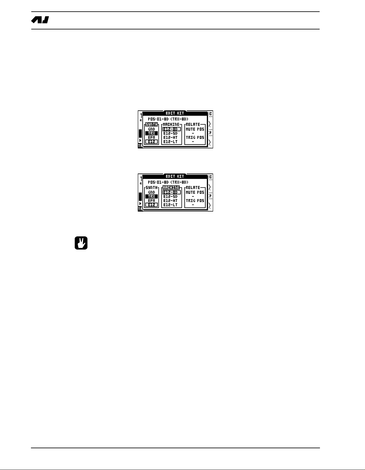
1. Use the arrow keys to move to the EDIT icon. Press [ENTER/YES] to open the edit win-
dow.
2. The EDIT KIT menu is used for both selecting which machine to load to a track and for
specifying mute and trig groups. The <SOUND SELECTION> LEDs indicate which track
you are editing, also shown at the top of the EDIT KIT window. To change track position,
turn the SOUND SELECTION wheel left or right, or hold down the [FUNCTION] key and
press the corresponding [TRIG] key.
machines for each track. First open
17
Page 26
THE SOUND SYNTHESIS OF MACHINEDRUM
3. After choosing what track you want to change, use [LEFT] and [RIGHT] to choose
between the SYNTH, MACHINE and RELATE columns. [LEFT] and [RIGHT] are also
used for selecting MUTE/TRIG POS focus in the RELATE column. Once you have
entered a column, it will be highlighted and now you can use [UP] and [DOWN] to
choose from the available options.
Select the MD-synth by first selecting the SYNTH column with the [LEFT] and [RIGHT]
keys. Then move the focus using [UP] and [DOWN] to select the MD-synth of your
choice.
4. When you are satisfied with your choice, press [RI
GHT] once to move the focus to the
MACHINE column. Select the machine using [UP] and [DOWN].
5. Finally you need to press the [ENTER/YES] key to confirm your selection. This will load
the machine with every value set to default.
• If you want to load a machine and keep the previous settings of the TRACK
EFFECT and ROUTING pages, hold [FUNCTION] while pressing the [ENTER/YES]
key.
• You can preview sounds without loading them. While in the EDIT KIT menu, make
ure that the <RECORD> LED is not lit and that the focus is on the MACHINE col-
s
umn. Then press the [TRIG] key corresponding to the active track. You will now
hear the default sound of the chosen machine.
• The MD-synth and the machine currently selected are shown as inverted text. The
focus, when moved away from the original selection, is a square window. Once
[ENTER/YES] is pressed, the current focus will be selected, thus changing the
focus to inverted text.
18
SETTING MUTE AND TRIG RELATIONS OF A KIT
Mute groups are useful for interleaving drums such as open and closed hi-hats. Trig groups
can be used for making layered drums, consisting of two drums on different tracks that are
triggered by one drum trig only.
Page 27
THE SOUND SYNTHESIS OF MACHINEDRUM
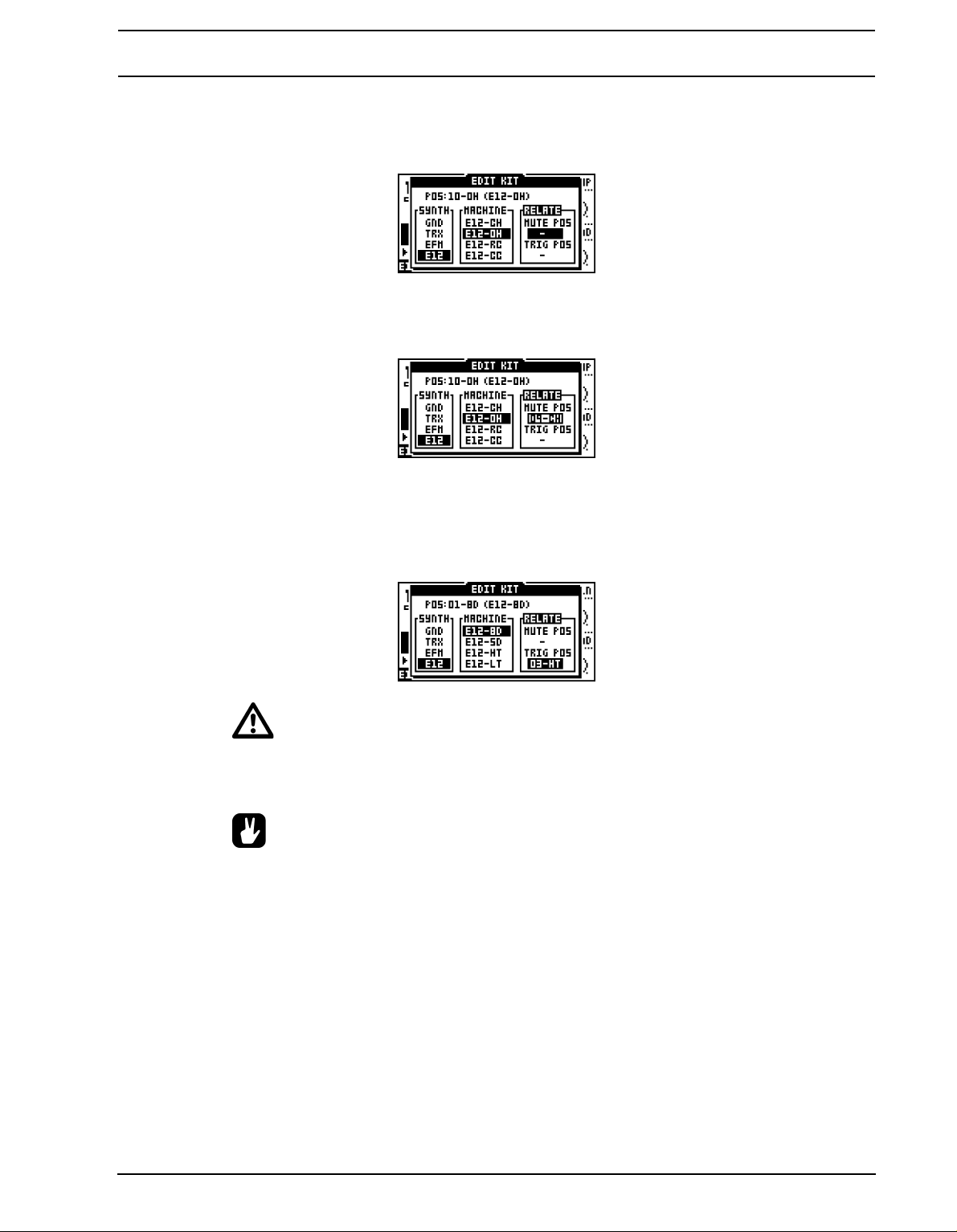
1. In the EDIT KIT menu, move the focus using the [L
EFT] and [RIGHT] keys to the
RELATE column. [LEFT] and [RIGHT] are also used for selecting the MUTE/TRIG POS
focus.
2. The mute relation is used for interleaving drums, suc
h as open and closed hi-hats which
are supposed to stop the sound of each other when played. Use the [UP] and [DOWN]
keys to select which track is muted when the current machine is triggered.
3. The trigger relation is used for layering sounds. It can either be used to make a sound
richer or to combine two entirely different machines to make a new type of percussion.
Use [LEFT] and [RIGHT] to move to the TRIG POS position. Use the [UP] and [DOWN]
keys to select which track will be played in addition to the current when it is trigged. Confirm the selection by pressing the [ENTER/YES] key
• You can not use TRIG relations in a chain. If the bass drum is set to trigger the
snare, and the snare is set to trigger the cymbal, only the bassdrum and snare will
be played when the bass drum is triggered.
• Layering is a very powerful way to expand the sound palette of the SPS-1 MKII/
SPS-1UW MKII. Try using filtering to obtain the low frequency characteristics from
one sound and combine it with the higher frequencies from another. This is especially useful when creating new and interesting bass drum sounds.
COPY MACHINE
You can copy one machine and its settings from one track to another. It is also possible to
copy the current machine and its settings to another kit.
19
Page 28
THE SOUND SYNTHESIS OF MACHINEDRUM
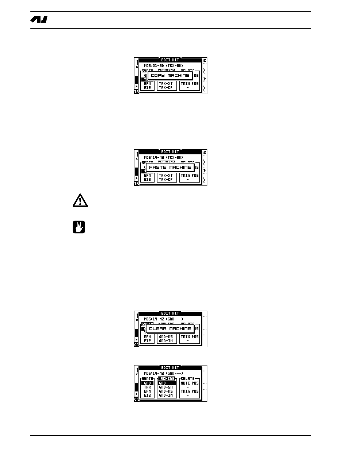
1. In the edit kit menu, press and hold [FUNCTION] and then press [RECORD]. A mes-
sage saying “COPY MACHINE” appears.
2. The settings are placed in the machine copy buffer. Now you can either change track
using the SOUND SELECTION wheel, or load a new kit and select a target track in
there.
3. Once the target track is selected, press and hold [F
UNCTION] and then press [STOP] to
paste the machine settings from the copy buffer. A message saying “PASTE MACHINE”
appears.
• Any previous machine settings will be overwritten when pasting.
• Once the machine is copied into the copy buffer, it can be pasted many times to
several tracks or kits. It will stay in the buffer until it is replaced by a new one.
• The UNDO command is available for this operation. Press the [FUNCTION] +
STOP] once more to undo the paste operation.
[
CLEAR MACHINE
It is possible to clear a track, so no machine is connected to it.
1. In the EDIT KIT menu, press and hold [FUNCTION] and then [PLAY] to clear the
machine. A message saying “CLEAR MACHINE appears.
2. A track that you have used the clear machine function on will be displayed like this:
20
Page 29
THE SOUND SYNTHESIS OF MACHINEDRUM
• The clear machine operation can be undone by performing the operation one
more time. The message “UNDO MACHINE” will be shown in the display.
MACHINE PARAMETER EDITING
Machines are controlled by up to eight synthesis parameters that are accessed with the
DATA ENTRY knobs.
Press the [SYNTHESIS/EFFECTS/ROUTING] key until the <SYNTHESIS> LED is lit. The
rightmost text of the machine information area at the bottom left will show “SYNT” for synthesis. The machine parameters are now controlled by the DATA ENTRY knobs.
• Changes are not stored to the kit unless it is saved. Please see section “SAVING
AND NAMING A KIT”, on page 15 for information about saving kits.
For more information on specific parameters of the different machines, please see “Appendix A: MACHINE REFERENCE“.
21
Page 30
THE TRACK EFFECTS
THE TRACK EFFECTS
The TRACK EFFECT system is available for all 16 tracks as an extension to the machine
percussion synthesis. The track effects consist of individual effects for every track.
The effects that are available for each track are:
• Amplitude modulator
• 1-band parametric EQ
• Adjustable lo/hi/bandpass Filter
• Sample rate reduction
o access the track effects, press the [SYNTHESIS/EFFECTS/ROUTING] key until the
T
<EFFECTS> LED is lit. The rightmost text of the machine information area at the bottom
left will show “TFX” for effects. The TRACK EFFECT parameters for the active track are
now controlled by the DATA ENTRY knobs.
• The TRACK EFFECT system is a very powerful sound shaping tool. Use it to either
dramatically alter or subtly change the sound of a machine.
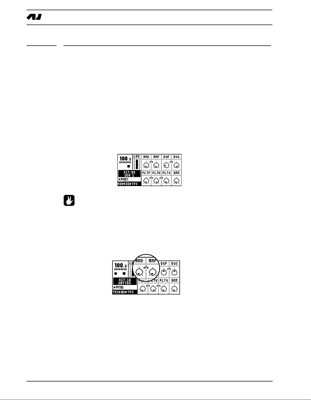
AMPLITUDE MODULATOR
The amplitude modulator is essentially a volume contr
quency oscillator. It is also known as a tremolo. The frequency of the Machinedrum amplitude modulator can be very high, allowing extreme effects.
AMD controls the the modulation depth.
AMF controls the modulation frequency.
ol which is controlled by a low fre-
22
Page 31

THE TRACK EFFECTS
TRACK EQ
Using the 1-band parametric EQ, you can boost or redu
ce a certain frequency band.
EQF controls which center frequency that will be affected by the EQ gain.
EQG controls the EQ gain. If set to a negative value, the volume of the frequency centered
around the EQF parameter will be reduced.
• If you find a bass drum lacking in punch, try adding a little EQ-gain in the lower
frequencies.
FILTER
The TRACK EFFECT system offers a resonant 24dB lo/hi/band-pass filter. The parameters
are untraditional, giving the user control of both the low and high filter cutoffs, as well as a
variable gap bandpass filter.
FLTF controls the base filter cutoff frequency. When the FLTW parameter is set to its highest value, changing the FLTF parameter has the function of a high-pass filter. When the
FLTF parameter is set to zero, the highpass-Q is disabled.
The illustration below shows the function of the filter.
FLTW controls the filter gap width, that is the distance between the highpass and lowpass
cutoff frequencies. When the FLTF is set to its minimum value, changing the FLTW param-
23
Page 32

THE TRACK EFFECTS
eter has the function of a low-pass filter. When the FLTW parameter is set to its maximum,
the lowpass-Q is disabled.
FLTQ controls the filter quality Q parameter. The Q value controls how much the volume is
boosted around the low pass and high pass filter cut off frequencies.
THE SAMPLE RATE REDUCER
The sample rate reduction reduces the sample rate usi
ng sample and hold.
SRR controls the amount of sample rate reduction.
24
Page 33

THE ROUTING PAGE
THE ROUTING PAGE
The ROUTING page controls routing of the sound through the distortion, volume and pan,
to the effect buses and also basic LFO control.
To access the ROUTING page, press the [SYNTHESIS/EFFECTS/ROUTING] key until the
<ROUTING> LED is lit. The rightmost text of the machine information area at the bottom
left will show “ROUT” for routing. The routing parameters for the active track are now controlled by the DATA ENTRY knobs.
DISTORTION
The distortion is applied after the TRACK EFFECTS but
before volume and pan.
The DIST parameter controls the signal overload distortion.
VOLUME
This volume control is separate from the LE
V overall gain control. You can control track
volume by parameter locks or by using the LFO system. The ACCENT feature can also be
used to affect volume of a track.
VOL controls the volume of the track
See section “LOW FREQUENCY OSCILLATORS (LFO’s)”, on page 32 for more information on LFO’s.
See section “PARAMETER LOCKS”, on page 12 for more information on parameter locks.
See section “ACCENT TRACK”, on page 45 for more information on the accent feature.
25
Page 34

THE ROUTING PAGE
• The LEVEL overall gain control can not be locked or controlled by an LFO.
Instead, use the VOL parameter.
PAN
Here you control the stereo pan for the main stereo outputs. The default value is 0, which
places a sound in the center. When a track is assigned to an individual output, the PAN
parameter has no effect.
PAN positions the sound in the stereo field. A value of -64 will pan the sound hard left, a
value of +63 will pan the sound hard right.
• To get a more spacious sound, try to spread out the tracks in the stereo field using
the PAN parameter. Note though that the normal placement of the bass drum is
almost always in the center.
DELAY SEND
This is a send to the RHYTHM ECHO DELAY of the STEREO MASTER EFFECT system.
When a track is assigned to an individual output, no delay will be applied to the sound.
DEL controls the amount of signal that will be sent to the RHYTHM ECHO delay.
See page 29 for more information on the RHYTHM ECHO delay.
REVERB SEND
This is a send to the GATE BOX reverb of the STEREO M
a track is assigned to an individual output, no reverb will be applied to the sound.
ASTER EFFECT system. When
26
REV controls how much signal will be sent to the Machinedrum GATE BOX reverb.
See page 30 for more information on the GATE BOX Reverb.
Page 35

THE ROUTING PAGE
LFO CONTROL
These parameters are identical to those found in the
LFO menu.
LFOS controls the speed of the LFO
LFOD controls the modulation depth of the LFO
LFOM controls the mix between the two selectable LFO waveforms.
See section “LOW FREQUENCY OSCILLATORS (LFO’s)”, on page 32 for more information about the LFO’s.
27
Page 36

THE STEREO MASTER EFFECT SYSTEM
THE STEREO MASTER EFFECT SYSTEM
The STEREO MASTER EFFECT system includes the RHYTHM ECHO delay, the GATE
BOX reverb, the MASTER EQ equalizer and the DYNAMIX dynamic processor (compressor).
The MASTER EQ and DYNAMIX processor effect the final stereo main out signal. The
RHYTHM ECHO and GATE BOX reverb can be fed signals from each of the 16 tracks
using the delay and reverb send parameters All master effect settings are saved as a part
of the kit. The MASTER EFFECTS is only available on the main outputs. You can’t use
them on the individual outputs.
• Even though you can’t parameter lock the master effects, you can still control
them using CTRL-machines. For more info about this, please see “Appendix A:
MACHINE REFERENCE“.
To access the STEREO MASTER EFFECT menu, follow the steps below.
1. Press the [KIT] key to open the kit menu.
2. Move to the MASTER FX icon, and press [E
menu.
3. Use the [LEFT] and [RIGHT] arrow keys to select the effect you wish to edit.
NTER/YES] to open the master effect
• Since the master effect settings are stored in the kit, it is important to save the kit
if you wish to keep the changes.
28
Page 37

THE STEREO MASTER EFFECT SYSTEM
THE RHYTHM ECHO DELAY
The RHYTHM ECHO delay is a multi-functional single ta
delay time. Some of its functionality can resemble tape loops and solid state CCD delays.
The delay time is synced to the tempo setting.
TIME controls the actual delay time. It is relative to the current tempo, and it is measured in
128th notes. For instance, for a two beat delay (8 16th notes) TIME should be set to 64.
MOD controls the delay time modulation depth.
MFRQ controls the delay time modulation frequency.
FB controls the delay feedback amount. The feedback is taken after the filter but before the
out gain control. FB set to central position with filter totally open gives unity feedback.
p delay with realtime adjustable
FILTF is the filter base frequency parameter. Please refer to section “FILTER”, on page 23
for a description of the functionality of the filter.
FILTW is the filter width parameter. Please refer to section “FILTER”, on page 23 for
description of the function.
MONO is the feedback panning control parameter. A low value gives ping pong style delay,
a high value preserves the stereo information, and a central position brings the delay feedback into the central panning position.
LEV is the out gain level control of the RHYTHM ECHO delay.
• Watch out if you are using FB levels greater than 63. The sound level of the
delayed signal will then constantly increase.
• To get a robotic effect on your drum sounds, turn up the delay send parameter
(DEL) for all sounds, set TIME to 1 and turn up FB to 55.
• You can use the RHYTHM ECHO delay to obtain pseudo stereo effects. Turn up the
DEL send of the sound you want to affect and in the RHYTHM ECHO delay menu,
turn TIME to 1, FB to zero and the MONO parameters to zero. Then set the PAN
parameter of the sound to either hard left or hard right.
29
Page 38

THE STEREO MASTER EFFECT SYSTEM
THE GATE BOX REVERB
The GATE BOX reverb brings HiQ reverb tailored for percussion, with gating possibilities
for extra effects.
DVOL is the delay to reverb level parameter. This parameter allows the output of the
RHYTHM ECHO to be routed into the GATE BOX reverb.
PRED is the pre-delay parameter. The direct and delay signal mix is delayed by an amount
of time to give the impression of the reverbation arriving after the sound.
DEC is the decay time parameter. Decay time is the time it takes for the reverbation to die
out after a sound has ended. The decay parameter has a span of 0.5 to 3 seconds.
DAMP is the damping control parameter. Damping decreases the high frequencies to give
the impression of soft walls.
HP is a high-pass filter, filtering the output from the reverb.
LP is a low-pass filter, filtering the output from the reverb.
GATE sets the gate time. The reverbated signal is gated after this time, if the signal level is
low. The maximal value for this parameter gives infinite time - in other words, the gate is off.
LEV is the output level parameter of the GATE BOX reberb.
• Sometimes a small amount of gated reverb can be used on snare drums to make
them more distinct. If you are looking for the sound popular in the 1980’s, apply a
fairly large amount of gated reverb to the drum sounds.
MASTER EQ
The MASTER EQ equalizer is the final frequency shaping tool. It supplies one low shelf
and one high shelf filter that allow you to boost or reduce the high and low frequencies. It
also brings one parametric equalizer with frequency and Q-control.
30
LF is the cut/boost frequency parameter of the low shelf filter.
LG is the low shelf gain parameter that controls how much the low frequencies should be
boosted / reduced between -15dB and +15dB.
Page 39

THE STEREO MASTER EFFECT SYSTEM
HF is the cut/boost frequency parameter of the high shelf filter.
HG is the high shelf gain parameter that controls how much the high frequencies should be
boosted / reduced between -15dB and +15dB.
PF is the parametric EQ frequency parameter, that is the center frequency of the parametric EQ band.
PG is the parametric EQ gain parameter. It controls how much the parametric EQ should
boost or reduce between -15dB and +15dB, at the frequency set by the “PF” parameter.
PQ is the parametric EQ Q factor. The Q controls the width of the band that is boosted or
reduced by the parametric EQ. High Q-values give a narrow band.
GAIN is the final out volume control. This parameter allows you to adjust the out volume of
the main stereo out.
THE DYNAMIX DYNAMICS PROCESSOR
The DYNAMIX dynamics processor is specially designed for compressing percussive
sounds.
ATCK controls the attack time, which is the time it takes the volume detector to react to the
Attack part of the sound signal. Long attack times let fast transients through the compressor.
REL controls the release time. This is the time it takes the volume detector to react to the
Release part of the sound signal. A long release time lifts the signal level as a sound
decays, flattening the dynamics.
TRHD sets the threshold level where the signal starts getting compressed (from -48 to
0dB).
RTIO controls the ratio by which the signal is compressed, when the threshold level is
reached. The ratio has a value in the range 1:1 to 1:256.
KNEE controls the soft knee transition. It makes the transition between compressed and
uncompressed signal smoother, by softening the knee. A low value gives a hard knee.
HP is the side chain High pass filter. This parameter highpass filters the sidechain signal of
the Compressor, so that it does not react to bass.
OUTG out gain raises the signal level. This is used to make up for the gain lost in the compressor.
MIX controls the cross mix between the compressed signal and the original signal. A high
value bypasses the DYNAMIX processor.
31
Page 40

LOW FREQUENCY OSCILLATORS (LFO’s)
LOW FREQUENCY OSCILLATORS (LFO’s)
Each kit in the Machinedrum has 16 assignable low frequency oscillators (LFO), which can
be used to modulate track parameters. The speed of the LFO is synchronized to the global
tempo.
Each of the 16 LFO’s offers two synchronized waveforms. A mix control allows the output
to be set to any mix between the two waveforms. LFO EDIT
To edit an LFO, follow the steps described below.
Press [FUNCTION] and hold it, then press [SYNTHESIS/EFFECTS/ROUTING] to open
the LFO edit window. Use the SOUND SELECTION wheel to select the LFO to edit.
TRACK displays the target track for the chosen LFO. The LFO’s are by default mapped to
control their own tracks, but they can be set to modulate any track, including other LFO’s
for extra complex modulation waveforms.
PARAM selects the parameter you wish the LFO to modulate. All SYNTHESIS, TRACK
EFFECTS and ROUTING parameters are accessible by the LFO. You can modulate
another LFO by targeting the track it is assigned to, and select either its SPEED, DEPTH or
SHMIX parameters with the PARAM control.
SHP1 selects which waveform shape that can be used by the LFO. There are six types of
available LFO waveforms:
• Triangle
• Saw
• Square
• Linear decay
• Exponential decay
• Random
HP2 offers inverted waveforms of the ones available in SHP1.
S
UPDTE controls the behaviour of the LFO. If the UPDTE parameter is set to “FREE”, the
LFO will never retrig. It will then continue to run regardless if new notes are trigged. If
UPDTE is set to “TRIG” the LFO is re-started each time the track is triggered. “HOLD” is a
sample and hold function, which freezes the value of the waveform at the time when the
track is triggered. It will remain frozen until trigged again. Note that LFO’s are only ever
restarted by trigging the corresponding track.
32
SPEED sets the update speed relative to the tempo in 1/128 note steps.
Page 41

LOW FREQUENCY OSCILLATORS (LFO’s)
DEPTH controls how much the LFO will affect the sound.
SHMIX is a balance control. When set to zero the LFO only uses the SHP1 waveform as
modulation. At its maximum, only modulation by the SHP2 waveform is used.
Below is an illustration showing the behaviour of the waveforms of the LFO’s when set to
the different UPDTE options.
• As the LFO settings are stored in the kit, it is important to save the kit if you wish
to keep the changes.
• The SPEED, DEPTH and SHMIX parameters are also available from the ROUTING
page. As the parameters of the ROUTING page can be controlled by parameter
locks and even by other LFO’s, this can be a source for highly advanced LFO setups.
33
Page 42

LOW FREQUENCY OSCILLATORS (LFO’s)
• If you select the same destination for two different LFO tracks their outputs will be
added, making advanced layered LFO’s possible.
• You can let a number LFO’s control several parameters of a machine. This allows
for percussion sounds that are constantly changing.
• Note that an LFO can modulate another LFO’s parameters as well, as long as the
modulated LFO is on a higher track. The LFO 03 can modulate the parameters of
the LFO 04, but not vice versa.
• Copy, paste, clear and undo functions are available for the LFO’s.
34
Page 43

THE PATTERN SEQUENCER
THE PATTERN SEQUENCER
The sequencer is a central part of the Machinedrum. It is designed to be an inspirational
tool for pattern based rhythms.
The sequencer is designed both for live and studio use. The patterns can either be trigged
individually from the user interface, trigged by MIDI commands or they can be linked
together to form a song.
The sequencer has two main modes of operation, called PATTERN mode and SONG
mode. We will start by taking a look at the PATTERN mode and move on to the SONG
mode, but first we will take a look at a very central concept of the Machinedrum.
CLASSIC VS EXTENDED
The sequencer is tied to parameter control and kit selection in different ways, depending on
he editing mode currently selected.
t
The key [CLASSIC/EXTENDED] switches between the CLASSIC and the EXTENDED
mode, and the adjacent LED indicates which mode is currently active.
CLASSIC EDITING
In CLASSIC mode, the SPS-1 MKII/SPS-1UW MKII will behave much like a traditional
drum machine. In this mode, patterns simply keep trig information and have no associated
kits or parameter locks. Changing patterns will not recall any kit.
EXTENDED EDITING
In EXTENDED mode, each pattern is associated with a certain kit, which will be recalled
when the pattern is played. This way, you know playing a certain pattern always gives the
same result. In this mode, patterns also keep parameter lock data. See section “PARAMETER LOCKS”, on page 47 for more information about parameter locks. Working with
parameter locks in EXTENDED mode is the key to many unique Machinedrum possibilities.
• In EXTENDED mode, be careful to save any changes you have made to your kit
that you want to keep. Changing a pattern might change kit and then you will lose
the old kit settings.
• In EXTENDED mode, if two patterns use the same kit, the kit will not be reloaded
when changing pattern.
35
Page 44

THE PATTERN SEQUENCER
TEMPO
THE TEMPO SCREEN
The TEMPO screen is opened by pressing the [TEMPO] key.
Now you can use the SOUND SELECTION wheel to change the current tempo in integer
steps. The [UP] and [DOWN] arrow keys change the decimal part of the tempo. Holding
[FUNCTION] while editing the tempo will delay the actual change of tempo until you
release the key.
• You can temporarily shift the tempo up or down by 10% by pressing the [LEFT] or
[RIGHT] arrow keys. This is very handy when manually syncing your Machinedrum to a turntable. Note that you do not need to be in the tempo screen to perform this tempo shift.
TAP TEMPO
To tap a tempo, hold the [FUNCTION] key and tap the [TEMPO] key at a steady rhythm.
After four consecutive taps the average tempo of the taps will be set as the new tempo and
it will be showed in the TAP TEMPO window. You can continue tapping the [TEMPO] key,
the tapped tempo average will continue updating.
EXTERNAL SYNCHRONIZATION
The Machinedrum SPS-1 MKII/SPS-1UW MKII can be set to
either internal or external syn-
chronization.
When in internal clock mode the Machinedrum outputs a high quality MIDI clock on the
MIDI OUT port. This can be used for keeping external gear in sync with the Machinedrum.
When in external midi clock synchronization mode the SPS-1 MKII/SPS-1UW MKII will stay
in sync with an external MIDI clock if present. When in external clock mode the tempo in
the upper left corner of the base LCD screen will show “EXT” for external synchronization.
The tempo screen will show the current average tempo. For more information about this,
see section “SYNC”, on page 73.
36
• The tempo is not stored in a pattern or a kit. However, songs can store tempo
changes.
Page 45

THE PATTERN SEQUENCER
PATTERN MODE
To edit a pattern, first make sure that the <PATTERN> LED is lit by toggling the [
SONG] key. Then select a pattern as described below. Load a kit that you want to use.
Then edit the pattern, either by using GRID RECORDING or LIVE RECORDING.
PATTERN SELECTION
The Machinedrum has 8 banks of 16 patterns each. The banks are named
A,B,C,D,E,F,G,H. The [BANK] key selects between pattern banks A to D and E to H.
To select a pattern, press and hold the bank name key while pressing the [TRIG] key. For
selecting pattern A05, first make sure the <BANK> LEDs indicate that banks A to D are
selected, then press and hold key [A/E] while pressing the fifth [TRIG] key.
While the [BANK] keys are pressed you can tell which patterns are uninitialised by the 16
<TRIG> LEDs. LEDs that are lit indicate that the corresponding pattern contains data. You
will also see which pattern that is currently selected. The <TRIG> LED corresponding to
the active pattern will give off a rapid double blink.
The [BANK] keys are “sticky”, which means that if you let them go without pressing any
[TRIG] key you still have around two seconds for selecting your pattern. This simplifies one
hand operation of the Machinedrum. A message on screen will indicate that the [BANK]
key still is active and a graphic represantation will tell how much time is left for selecting
your pattern.
PATTERN/
If pattern selection is done while the sequencer is playing, the selected pattern will not be
actived until the current pattern has played to its end. You will see the change in the display
as described in section “THE LCD USER INTERFACE”, on page 9.
PATTERN CHAINING
You can use pattern chaining to cue up patterns to be
played after each other in a loop, like
a simple live sequencer for patterns. In PATTERN mode, hold a [BANK] button and then
press the [TRIG] keys corresponding to the patterns you want to chain. The patterns will be
chained in the order you select them. It is only possible to chain patterns from one bank,
and each pattern may only be chained once. Chaining is indicated by a double arrow
between the current and the next pattern.
[STOP] changes pattern if a pattern was previously selected as next pattern. That means
that if pattern A01 is started and A02 is cued to play after pattern A01, pressing [STOP]
and then [PLAY] will start playing at A02.
PARAMETER TWEAKING
By pressing the [F
UNCTION] key and turning one of the DATA ENTRY knobs, the actual
parameter will be changed for every track. This is a quick way to make patterns sound dramatically different. Note that the values of the manipulated parameters may not be restored
when you turn them back the same amount of steps you first changed them. If track 1 has
a FLTW setting of 0 and track 2 has a FLTW setting of 127 and you change the FLTW
parameter 10 steps clockwise using [FUNCTION] + DATA ENTRY knob, track 1 will display
a FLTW value of 10 while track 2 still will have a value of 127.
• [FUNCTION] + DATA ENTRY knob will not affect UW RAM Recording Machines or
MIDI machines. However, if the active track contains a MIDI machine, [FUNCTION]
+ a DATA ENTRY knob will only affect other tracks containing MIDI machines. The
37
Page 46

THE PATTERN SEQUENCER
same condition applies if the active track is a UW RAM Recording machine. Note
that CTRL machines are not affected by this function as active track or otherwise.
• When in the TRACK EFFECTS section, use [FUNCTION] + DATA ENTRY knob E or
F to apply a filter sweep to the whole pattern.
• By pressing [FUNCTION] + [CLASSIC/EXTENDED] the saved kit will reload
instantly. This comes in handy when a pattern has been heavily manipulated and
you want to quickly revert it back to its original settings.
SCALE SETUP
It is possible to change the length and step resoluti
4 bars (16 steps) of length.
By pressing the [FUNCTION] key and then the [SCALE SETUP] key, you can set the scale
length and replay speed mode.
on of a pattern. By default a pattern is 4/
There are three values that can be changed in the SCALE SETUP screen. The focus is
moved with the [LEFT] and [RIGHT] keys.
• The leftmost number selects the number of steps in the pattern. The maximum
number of steps is determined by the total length. Use [UP] and [DOWN] to
increase/decrease the number of steps. The [TRIG] keys can also be used to set
the end step.
• The second value selects the total length of the scale. This is either 16, 32, 48 or
4 steps. If you use 17 steps or more in a pattern, the [SCALE SETUP] key is used
6
in GRID RECORDING mode to toggle the focus between the different pattern
pages.
• The third parameter is the tempo multiplier. There are four possible settings, “1X”,
“2X”, “3/4X” and “3/2X”. 2X allows a pattern to be played back at twice the global
tempo. 3/4X allows a pattern to be played back at three quarters of the global
tempo. 3/2X will play back a pattern twice as fast as the 3/4X setting. Double speed
is useful for increasing the step resolution to 32th notes. Three quarter-speed is
useful when the Machinedrum is playing alongside other instruments set to the
same BPM and you want the Machinedrum to play triplets.
• Even though you set a pattern to have a certain length using scale setup, you can
change this row by row in the song editor. See section “SONG MODE”, on page 51
for more information.
• When changing pattern length from 16 to 64 steps, the first 16-step pattern page
will be copied to all the subsequent pages, if the last other pages previously have
not been programmed.
38
Page 47

THE PATTERN SEQUENCER
COMPOSING A PATTERN
GRID RECORDING
G
RID RECORDING is a method of percussion composing that was first developed in vin-
tage drum machines. In its default state, the 16 [TRIG] keys represent 1 bar of 16th notes.
1. To start recording, press the [RECORD] key. The <RECORD> LED on the left side of the
key is now firmly lit.
2. Select the track you wish to edit using the SOUND SELECTION wheel.
3. You can press [P
The LEDs above the [TRIG] keys will start to run to indicate the current step in the pattern. It will loop over and over, until you press [STOP] to stop the playback or [PLAY] to
pause it. The pattern page being played is indicated by the flashing of the corresponding
<PATTERN PAGE> LED.
4. Press the [TRIG] keys to toggle percussion trigging for the corresponding step. The
LEDs above the [TRIG] keys will indicate what steps will be triggered.
5. If the pattern contains more than 16 steps, switch to the pattern page you want to edit by
pressing the [SCALE SETUP] key. The active pattern page is being indicated by a firmly
lit <PATTERN PAGE> LED.
LAY] if you would like to have the pattern playing during composing.
• In the Machinedrum, you work directly in the pattern memory. There is no need to
save patterns. If you wish to keep the data in a pattern, you will have to copy it to
another pattern before you begin editing it. See section “PATTERN COPY”, on
page 43 for more information on copying pattern data.
• If you exit the recording mode, you will not get the running LEDs above the [TRIG]
keys during playback.
• The copy, clear, paste and undo functions operate on a specific track when in
GRID RECORDING mode. See section “TRACK COPY” on page 41.
• The copy, clear, paste and undo functions operate on the full pattern when not in
GRID RECORDING mode. See section “PATTERN COPY” on page 43.
• An easy way to experiment with a pattern is to move all the trigged notes of a track
forwards or backwards. While in record mode, hold down [FUNCTION] while
pressing the [LEFT] or [RIGHT] arrow keys to perform this move. This is especially useful on tracks containing snare drums.
PATTERN PAGE FUNCTIONALITY ON MKI UNITS
On the MKI the pattern page is indicated by the LEDs <1/16>,<1/32:1> and <1/32:2>.
When patterns are up to 16 steps in length only the <1/16> LED is lit. When the pattern is
longer the <1/32:1> LED indicates the editing position being on the first page and <1/32:2>
indicates the second page.
LIVE RECORDING
Live recording is the second method of recording drum trigs. In this recording mode, the
[TRIG] keys are played like a drum set. The current kit is assigned to all [TRIG] keys, so all
16 tracks can be accessed at once.
1. To start recording using direct composing, hold [RE
CORD] while pressing [PLAY]. This
starts the sequencer recording and the <RECORD> LED starts to flash.
39
Page 48

THE PATTERN SEQUENCER
2. You can now lay down your beat in real time by triggering the machines in your kit with
the [TRIG] keys.
3. To stop recording, press [STOP]. To exit recording but keep the sequencer playing the
pattern, press [PLAY].
4. To remove notes recorded, hold [EXIT/NO] and a [TRIG] key. All notes will be removed
for the part of the track that is played while the [EXIT/NO] and [TRIG] keys are held.
5.
• All live recorded data will be quantised to the current scale resolution (16th or
32nd notes).
NOTE COPY
It is possible to copy a note trig, complete with all parameter lock settings, and paste it to a
new location in the track.
1. Make sure you are in GRID RECORDING mode, indicated by the <RECORD> LED giv-
ing off a steady light.
2. Press and hold the note trig you want to copy and press the [RECORD] key. A window
saying “COPY NOTE” will appear.
3. Hold the [TRIG] key correspondning to the location you want to paste the note to and
press the [STOP] key to complete the paste operation. A window showing “PASTE
NOTE” will be shown.
CLEAR NOTE PARAMETER LOCKS
Instead of removing the parameter locks from a note y
ou can also use the clear note locks
command.
1. Make sure you are in GRID RECORDING mode. The <RECORD> LED should be lit.
2. Hold and press the [TRIG] key you whose content you want to clear. Then press [PLAY]
to clear the note. The message “CLEAR NOTE LOCKS” will appear.
40
Page 49

THE PATTERN SEQUENCER
• The clear note lock operation can be undone by performing the clear note opera-
tion one more time. The message “UNDO NOTE LOCKS” will be shown in the display.
TRACK COPY
In GRID RECORDING mode, it is possible to copy the contents of one track to another.
1. Make sure you are in GRID RECORDING mode, indicated b
y the <RECORD> LED giv-
ing off a steady light. Select the source track using the SOUND SELECTION wheel.
2. Hold [FUNCTION] while pressing [RECORD] to copy the data in the track.The message
“COPY TRACK” will be shown in the display.
3. Select the destination track using the SOUND SELECTION wheel.
4. Paste the data by pressing and holding [FUNCTION] and then pressing the [STOP] key.
A message saying “PASTE TRACK” will be shown in the display.
• The track data that is pasted consists of notes, the machine association, LFO set-
tings and, if in EXTENDED mode, parameter locks. If the LFO is set to affect a
parameter on the same track it is remapped as it is pasted. If the LFO is set to
affect a parameter of another track the destination is kept but the LFO depth is set
to zero to avoid confusing results.
• Pasting a track overwrites any previous notes, data and parameter locks.
• The paste track operation can be undone by holding down the [FUNCTION] key
while pressing the [STOP] key. A message saying “UNDO TRACK” will be shown
in the display.
CLEAR TRACK
While in GRID RECORDING mode, it is possible to clear a track.
1. Make sure you are in GRID RECORDING mode. The <RECORD> LED should be lit.
41
Page 50

THE PATTERN SEQUENCER
2. When you are in the track you wish to clear, press and hold [FUNCTION]. Then press
[PLAY] to clear the track. The message “CLEAR TRACK” will appear.
• The clear track operation can be undone by performing the clear track operation
one more time. The message “UNDO TRACK” will be shown in the display.
TRACK PAGE COPY
In GRID RECORDING mode you can also copy one page of trig data and paste it to
another page.
1. Make sure you are in GRID RECORDING mode, indicated by the <RECORD> LED giv-
ing off a steady light. Select the source track using the SOUND SELECTION wheel.
2. Go to the page you want to copy by pressing the [SCALE SETUP] key.
3. Hold the [SCALE SETUP] key and press [RECORD]. A message saying “COPY PAGE”
page will appear.
4. Go to the pattern page you want to paste the copied page into by pressing the [SCALE
SETUP] key. Paste the data by holding [SCALE SETUP] while pressing the [STOP] key.
A message saying “PASTE PAGE” will be shown in the display
• Pasting a track page overwrites any previous notes, data and parameter locks.
• The track page paste operation can be undone by holding down the [SCALE
SETUP] key while pressing the [STOP] key. A message saying “UNDO PAGE” will
be shown in the display.
CLEAR TRACK PAGE
It is also possible to clear a track page.
1. Make sure you are in GRID RECORDING mode.
42
Page 51

THE PATTERN SEQUENCER
2. When you are in the track you wish to clear, press an
d hold [SCALE SETUP]. Then
press [PLAY] to clear the track. The message “CLEAR PAGE” will appear.
• The clear track page operation can be undone by holding the [SCALE KEY] and
pressing the [PLAY] key directly after the clear operation. The message “UNDO
PAGE” will be shown in the display.
PATTERN COPY
To copy the contents of a a pattern to another, follow the steps below.
1. Make sure you are not in GRID RECORDING mode, indicated by the <RECORD> LED
being unlit.
2. Select the source pattern. Hold [FUNCTION] while pressing [RECORD]. A message
“COPY PATTERN” will be shown in the display.
3. Change pattern to the destination where you wish to paste your pattern data by using the
[BANK] and [TRIG] keys.
4. Paste the data by pressing and holding [F
UNCTION] and then pressing the [STOP] key.
The message “PASTE PATTERN” will be shown in the display.
• The pattern data that is copied consists of notes, the kit association (in
EXTENDED mode) and parameter locks.
• Pasting a pattern overwrites any previous notes, data and parameter locks.
• The copy pattern operation will copy the whole pattern including unsaved kit
changes.
• You can undo the paste operation by holding the [FUNCTION] key and pressing
the [STOP] key.
43
Page 52

THE PATTERN SEQUENCER
CLEAR PATTERN
It is possible to clear a whole pattern of its contents.
1. Make sure you are not in GRID RECORDING mode.
2. Select the pattern you want to clear. Press and hold [FUNCTION]. Then press [PLAY] to
clear the pattern. A message “CLEAR PATTERN” will be shown in the display.
• The clear pattern operation can be undone by immediately performing the opera-
tion one more time. A message saying “UNDO PATTERN“ will be shown in the display.
TRACK MUTING
THE TRACK MUTE WINDOW
Tracks can be individually muted from the MUTE window. This is useful in a live setting,
you can mute out sounds in a looping pattern, thus creating variations.
1. Hold [FUNCTION] while pressing [A/E] to call forth the MUTE window.
2. In this window, there are 16 squares representing the
16 tracks. Use the [TRIG] keys to
toggle muting of the corresponding tracks. A muted track will be displayed as a “-” sign.
3. While holding [FUNCTION] and pressing the [TRIG] keys, the mute changes will be held
until [FUNCTION] is released. A track that is currently muted but will be unmuted when
[FUNCTION] is released is displayed as a “+” sign. A track that is currently not muted
but will be muted when [FUNCTION] is released is displayed as an “X” sign.
44
4. Release the [F
UNCTION] key to perform all the prepared mute operations.
Page 53

THE PATTERN SEQUENCER
MINIMISING THE MUTE WINDOW
While the MUTE window is active it occupies a large p
ortion of the LCD screen. This can
be disturbing if you want to work with mutes at the same time as you want to access the
sound parameters.
To avoid this problem, the MUTE window transforms to a small centered window when a
DATA ENTRY knob is accessed while in MUTE mode. To return to the big MUTE window,
press the [ENTER/YES] button.
• In songs, mutes can be programmed specifically per row. For more information,
see section “SONG MUTE” on page 55.
• A muted track remains muted, even when the pattern is changed or if SONG mode
is entered or exited.
• Drums already trigged and still making sounds will continue to sound when
muted, but further trigs will be masked. This allows the drums to fade out in a natural way.
ACCENT TRACK
The Accent feature is used for quickly changing the accentuation for either a pattern as a
whole or for individual tracks. Accent raises the volume at selected positions within a pattern or a track.
1. Hold down the [F
ACCENT window.
2. The accent value is set in steps up to 15, using [UP] and [DOWN] or the SOUND
SELECTION wheel.
3. Toggle the steps to be accented by pressing the [TRIG] keys. Accent is per default set to
ALL and will therefore affect the whole pattern. Place accents by pressing the [TRIG]
keys. Press the [RIGHT] arrow key if you want to accent individual tracks.
UNCTION] key while pressing the [B/F] key. This brings forth the
4. Move on to the next accent track by holding down [F
UNCTION] and pressing the [TRIG]
key corresponding to the track whose accent you want to set.
45
Page 54

THE PATTERN SEQUENCER
• You can copy, paste, clear and undo accent patterns, tracks and track pages.
Press [FUNCTION] + either the [RECORD], [PLAY] or [STOP] keys while the
ACCENT window is open to perform these operations on the accent pattern or
track. Press [SCALE SETUP] + either the [RECORD], [PLAY] or [STOP] keys if you
want affect the accent track page with these operations.
SWING
THE SWING WINDOW
wing is used for adding a rhythmic “shuffle” to a pattern or to individal tracks. By default,
S
the swing will affect every second 16th note, starting on step 2. This is how the swing pattern will be restored after a clear pattern operation and will give the traditional shuffle-style
swing for a 4/4 single speed pattern.
When changing to double speed mode in the SCALE SETUP menu (see page 38) you
need to modify the swing pattern to get the same result in single speed mode. In double
speed mode, activate swing for every fourth note, starting with the third note.
More advanced swing effects can of course be made with other swing pattern setups, but
that is outside the scope of this manual. To add swing to a pattern, follow the steps below.
1. Hold [FUNCTION] while pressing [C/G] to open the SWING window.
2. Use the SOUND SELECTION
wheel to set the desired amount of swing. The amount of
swing is set in percent. 50% is the default value, meaning that no swing will be applied,
and the maximum value is 80%.
3. The [TRIG] keys are used for toggling which pattern steps the swing will influence.
You can also have different swing settings for individual tracks. Note though that every
swing track will share the same percentage of swing. Here is how you set individual swing
tracks.
1. Hold [FUNCTION] while pressing [C/G] to open the SWING window.
2. Use the SOUND SELECTION wheel to set the desired amount of swing.
3. The [TRIG] keys are used for toggling which steps the swing will influence. Swing is per
default set to ALL which will affect the whole pattern. Press the [RIGHT] arrow key in
order to select individual swing tracks.
46
4. Once you have set the swing track and are satisfied,
move on to the next swing track by
holding down [FUNCTION] and pressing the [TRIG] key corresponding to the track
Page 55

THE PATTERN SEQUENCER
9 13
whose swing you want to set. Note though that all swing tracks use the same percentage of swing.
Below is a figure illustrating how notes are affected by various amounts of swing.
• You can copy, paste, clear and undo swing patterns and tracks. Press [FUNCTION]
+ either [RECORD], [PLAY] or [STOP] while the SWING window is open to perform
these operations. You can also copy, paste, clear and undo a swing track page by
pressing [SCALE SETUP] + either the [RECORD], [PLAY] or [STOP] keys.
• Try to swing only one or two tracks, for example the hi-hats, for creating rhythms
ith a different feel compared to un-swinged patterns.
w
• Experiment with using only a few swing trigs in a swing pattern. This will create
just a few notes that are slightly off beat which can add a great deal of movement
to a pattern.
PARAMETER LOCKS
A parameter lock is a parameter locked to a certain value for a specific step. Parameter
locks can be programmed in GRID RECORDING mode and recorded in LIVE RECORDING mode. For parameter locks to come into effect, you need to be in EXTENDED mode.
All SYNTHESIS, TRACK EFFECT and ROUTING parameters can be locked. Parameter
locks are a very important part of creating unique and dynamic patterns with the Machinedrum.
PARAMETER LOCKS IN GRID RECORDING MODE
To program parameter locks in GRID RECORDING mode, follow the steps below.
1. First make sure you are in GRID RECORDING mode, by verifying that the <RECORD>
LED is firmly lit.
47
Page 56

THE PATTERN SEQUENCER
2. Select the track you wish to do parameter locks for, using the SOUND SELECTION
wheel. Select a parameter page (SYNTHESIS, EFFECTS or ROUTING) for the DATA
ENTRY knobs.
3. Press and hold the [TRIG] key for the step where you want to add a lock. While holding
the [TRIG] key, you can now tweak the parameter of your choice with the DATA ENTRY
knobs. You can tell that the parameter has been locked by it being inverted on the LCD
screen. When the [TRIG] key is released, the trig for that position will hold the parameters that you just programmed. You can also click an unlocked DATA ENTRY knob once
to lock it to its current value.
4. You can verify which steps have parameter locks by lo
oking at the <TRIG> LEDs. A
firmly lit <TRIG> LED means that it is not locked, whereas a rapid interval flash indicates
it does have one or more parameter locks.
5. If you want to view the current parameter lock settings for a step, hold the [TRIG] key.
You can tell which parameters are locked by them being inverted on the screen.
6. To remove all parameter locks for a step, hold the [TRIG] key and press the [PLAY] key.
You can also remove the locks by deleting the trig and reinserting it.
7. To remove one of more parameter lock for a step, hold the [TRIG] key and click the
DATA ENTRY knob you want to remove the lock for. You can tell that the lock has been
removed by the inversion disappearing for the parameter clicked.
• A lock is a snapshot of a parameter setting. It changes the parameter value from
its original value stored in the kit, but only for that note trig. The parameter will
change back to its default state on the next trig if no further parameter locks are
made for that note and parameter.
• A pattern can have a total of 64 individually locked parameters divided freely
between all tracks and parameters. When a parameter is locked on one step, that
parameter can be locked to individual values on all the steps of the track.
• Parameter locks only work in EXTENDED mode, but changing mode to CLASSIC
ill not affect any pre-recorded locks. They will remain in the pattern, but they will
w
have no effect until the mode is set to EXTENDED again.
PARAMETER LOCKS IN LIVE RECORDING MODE
In LIVE RECORDING mode, you can record parameter locks live. To do this, follow the
steps below:
1. Go into live recording mode by holding down the [REC] button and then pressing the
[PLAY] key.
2. Select the track for which you wish to enter parameter locks by using the SOUND
SELECTION wheel or by pressing [FUNCTION] + the corresponding [TRIG] key. Select
a parameter page (SYNTHESIS, EFFECTS or ROUTING) for the DATA ENTRY knobs.
3. Record parameter locks by changing the corresponding DATA ENTRY knob while live
recording. When changing a parameter, the parameter lock will be set on the next note
played on the track. If a parameter is not changed between two drum trigs no parameter
lock will be made.
4. To remove specific parameter locks, press and hold [EXIT/NO] and a DATA ENTRY
knob. All parameter locks will be removed for that specific parameter and track on the
steps of the track that is played.
48
Page 57

THE PATTERN SEQUENCER
• It is often a good idea to edit and fine tune the parameter locks in GRID RECORD-
ING mode, after recording them in LIVE RECORDING mode.
PARAMETER LOCK SLIDE
The default behaviour for parameter locks is that the value changes exactly when the step
is played and not in between. By using slides, you can have the value of a parameter
locked on one step slide gradually to the value on the next. This behaviour is controlled by
the slide pattern or the slide tracks.
For a parameter to slide it needs to be parameter locked at two separate steps. If a slide
trig is set to the same step as there is a parameter lock, the parameter will slide to the next
parameter locked value. The speed of the slide is relative to the current tempo and the
slide is completed when the next position with a drum trig is reached.
To set slide trigs, follow the instructions below.
1. Hold [FUNCTION] wh
2. Use the [TRIG]
ile pressing [D/H] to open the SLIDE window.
keys to select the steps for which parameter locks will slide to their next
locked value.
To set individual swing tracks, just follow the instructions below.
1. Hold [FUNCTION] while pressing [D/H] to open the SLIDE window.
2. Slide is per default set to ALL which will affect the whole pattern. Press the [RIGHT]
arrow key to be able to set individual slide tracks.
3. Once you have set the slide track and are satisfied, move on to the next slide track by
holding down [FUNCTION] and pressing the [TRIG] key corresponding to the track
where you want to place slide notes. Use the [TRIG] keys to select the steps for which
parameter locks will slide to their next locked value.
49
Page 58

THE PATTERN SEQUENCER
• The speed of the slide is relative to the current tempo. The slide is always com-
pleted exactly when the next position with a drum trig is reached.
• Only parameters that are locked on the steps selected in the slide mode will slide
to their destination. Parameters that are unlocked will not slide.You can copy,
paste and clear slide patterns and tracks. Press [FUNCTION] + either [RECORD],
[PLAY] or [STOP] while the SLIDE window is open to perform these operations.
You can also copy, paste and clear a slide track page by pressing [SCALE SETUP]
+ either the [RECORD], [PLAY] or [STOP] keys. The paste and clear actions can be
undone.
50
Page 59

SONG MODE
SONG MODE
A song is basically a number of patterns which are played in sequence. Each step in a
song can have its own settings for pattern start position, pattern length, tempo, and mute
information. You can also loop segments of a song or jump between locations within a
song. All this makes for a very powerful way of arranging your patterns. A song can be up
to 256 steps long, and the memory holds 32 songs.
You enter song mode by pressing the [PATTERN/SONG] key, so that the <SONG> LED is
lit. The screen will change to make room for the song list:
LOAD SONG
o load a song from memory, you first need to open the SONG window by pressing
1. T
[FUNCTION] and the [KIT] key.
2. Move to the LOAD icon and press [ENTER/YES].
3. Choose the song you wish to load from the list by usi
keys, and press [ENTER/YES] to execute.
ng the [UP] and [DOWN] arrow
• Loading a song will destroy any unsaved current song settings. Make sure to
store unsaved work you wish to keep before loading a song.
• The song only holds the information on what patterns should be played in
sequence. Accurate playback of a song depends on the patterns it uses being
unchanged since saving. Otherwise the song might sound differently.
• Machinedrum SPS-1 MKII/SPS-1UW MKII recognises MIDI Song Pointer Position,
which means that you can control the position in the song list from an external
sequencer. Note that you cannot reach song positions inside loops.
51
Page 60

SONG MODE
PLAYING A SONG
1. Make sure that you are in SONG mode, and that a song is presently loaded.
2. To start the playback of a song, press [PLAY]. Pressing [PLAY] again pauses the play-
back.
3. To stop the playback, press [STOP].
NAVIGATING A SONG
The [UP]
and [DOWN] keys can be used to manoeuvre the two indicators on the left and
right sides of the new song list. Pressing [ENTER/YES] will move the song pointer to the
position of the arrows.
When playing the song the arrows will blink and at every fourth blink they point in the direction of the song position pointer. When repeating a row in a song the number of turns left is
indicated to the right of the current pattern display.
In song mode [STOP] holds the position and another [STOP] moves the position pointer to
the beginning of the song.
• Songs are played until the end and will then stop. Of course, infinite loops can
make songs that never end.
• The current tempo will change, if the song has tempo changes in it.
SONG EDITING
The Machinedrum song editor is where the song is built. Here patterns are assigned to the
song. The behaviour of the patterns is also set in the song editor.
52
1. Hold the [FUNCTION] key and press the [KIT] key to open the SONG window.
Page 61

SONG MODE
2. Move to the EDIT icon and press [E
NTER/YES] to open the EDIT SONG screen.
This is where you arrange your patterns into a song. You can edit the song while it is
playing. The two filled arrows on each side of one of the steps are the song position
pointers. They indicate which song step the sequencer is currently playing. In the header
of the menu, next to the text “EDIT SONG” there is a counter, indicating how many bars
and beats the song has played.
3. Use the [UP]
and [DOWN] keys to select the song row you wish to edit. The [LEFT] and
[RIGHT] keys allow you to move the focus between the pattern, repeat, offset, length,
BPM and mute settings. The SOUND SELECTION wheel alters the value of each setting.
4. The pattern settings are located in the PAT column. The SOUND SELECTION wheel is
used for choosing between patterns and functions. You can also select a pattern by holding the [BANK A-H] key and pressing a [TRIG] key.
5. The END mark indicates the end of the song. When this point is reached, the sequencer
will stop. You can also program loops in this column. See section “SONG LOOP”, on
page 54 for more information on loops.
6. The REP column controls how many times the current pattern will be repeated for that
particular row in the song.
7. Each row in the song can have its own BPM setting. Yo
u set the tempo in the BPM column. If you do not specify a BPM value on a step, the sequencer will use the last one
used in the song. If a song does not have any tempo settings, the sequencer will use the
current tempo.
• To insert a step in the song, use [FUNCTION] together with the [DOWN] key.
• To remove a step in the song, use [FUNCTION] together with the [UP] key.
• Copy, paste, clear and undo functions operate on rows in song edit
53
Page 62

SONG MODE
SONG ROW OFFSETS AND LENGTHS
The OF LEN column can be used to override the default start offset and length settings for
the pattern assigned to that row.
The default start of a pattern is always zero. This means it will start to play from the beginning. The default length is set from scale setup (see section “SCALE SETUP”, on page 38).
The song row offset and length functions can be used to build complex rhythm structures. It
can also be used for exchanging certain parts of a pattern for certain song rows in order to
add, for example, a fill at the end of a pattern.
SONG TRANSPORT
It is possible to start playback from any row positio
n in a song. To do this, move the editing
focus to the row you wish to start the playback from and press the [ENTER/YES] button. If
not in play mode, you will see the two filled arrows indicating the replay position move to
the current row.
If the song is currently playing when you select another row, you will first get two hollow
arrows on each side of the current row. The hollow arrows indicate which row will play next
once the current row reaches its end.
SONG LOOP
Song loops are a useful tool when creating a song. By
using this command you can limit
the number of rows and make the structure of the song clearer. They can also be used for
setting up pattern loops in order to extend the Machinedrum’s limit of maximum 64 steps
per pattern.
To create a loop, turn the SOUND SELECTION wheel in the PAT column to right before the
A01-pattern, after the END indicator. When a loop is selected the second edit column controls which row to loop from. Use the SOUND SELECTION wheel or [BANK A-H] together
with a [TRIG] button to change what row to loop to. The third column selects how many
times the loop should be executed. Use the SOUND SELECTION wheel to select how
many times the loop shall be executed. The loop count can also be set to infinity.
54
Page 63

SONG MODE
• Loops can be nested.
• A set of infinite loops can be very useful in a live setting. With a set of infinite
loops, the song transport functions can be used to jump between the looping patterns.
SONG JUMP
A loop can also be converted into a jump. A jump will
the row that you select. Insert a jump by turning the SOUND SELECTION wheel so that the
number of the second loop row becomes a number that is greater than the current row
number. The jump command will appear and no loop count column will be available. Use
the [RIGHT] arrow key to move the focus to the column where you insert which song row
you want the song position pointer to jump to.
refer to the song pointer position to
SONG HALT
If you set the loop to loop to the current row it will change to a HALT statement. When the
song pointer reaches a HALT statement it will pause the playback. You then need to use
the song transport controls as described on page 54 to select a new position to start from.
SONG MUTE
In songs, you can mute individual tracks for each row
. The mute pattern for each row is
accessed by moving the cursor to the MUT column and then pressing [ENTER/
YES].Tracks muted using song mute can not be unmuted using pattern mute.
This takes you to the familiar MUTE window as seen below.
55
Page 64

SONG MODE
In this window you can set the tracks that will be muted for the row. The standard pattern
mute, set by [FUNCTION] + [A/E], applies as well, so tracks muted there as well as in the
song mute are silent.
SAVE SONG
1. Open the SONG window by holding [FUNCTION] and pressing the [KIT] key.
2. Use the [LEFT]
and [RIGHT] keys to move to the SAVE icon. Press [ENTER/YES] to
call the SAVE SONG menu.
3. On the screen, you can find a list of the songs stored in memory. Use the [UP] and
[DOWN] keys to choose among the 32 song slots. Press [ENTER/YES] to select the slot
where you want to save your song.
4. A window opens where you can name the song:
Select characters using the SOUND SELECTION wheel. The arrow [LEFT] and
[RIGHT] keys move the cursor backwards and forwards on the line.
5. Pressing the [F
UNCTION] key gives access to the “high score” selection method, in
which you see all characters at the same time. Keep the [FUNCTION] key held while
navigating using the [LEFT], [RIGHT], [UP] and [DOWN] buttons. Release the [FUNC-
TION] key, when you have found the right letter.
56
6. Once you are done naming the song, press [ENTER/YES] to save it.
7. If you want to exit without saving a song, press [EXIT/NO].
• The commands copy, paste, clear and undo are available in the SAVE SONG and
LOAD SONG menus.
Page 65

GLOBAL SETTINGS
GLOBAL SETTINGS
The SPS-1 MKII/SPS-1UW MKII offers 8 different global settings positions. The multiple
global setups are useful for using the Machinedrum in more than one setup. You can have
one setup for studio use and another for live use, or maybe several different setups for different parts of your live set.
The items listed below are available in a the GLOBAL SETTINGS menu.
• MIDI base channel
• TRACK/PATTERN mappings for a MIDI keyboard
• Local control on or off
• Sysex send of pattern, song and kit data
• Sysex receive of pattern, song and kit data
• Program change settings
• Sample manager (Machinedrum UserWave only!)
• Output routings of tracks
• Trig in settings for external pads
• Sync settings
o select a global setting and edit it:
T
1. Press [FUNCTION] and then the [PATTERN/SONG] key to open the GLOBAL SET-
TINGS menu.
2. Go to the global setting slot you wish to use, and pr
3. If you wish to enter the menu for the selected slot, you can either press [ENTER/YES]
once more or move the focus to the ENTER field and press [ENTER/YES].
ess [ENTER/YES] to select it.
MIDI
Here you set how the Machinedrum will handle both MIDI and SYSEX data. For the
Machinedrum UserWave, the sample manager is also found here.
57
Page 66

GLOBAL SETTINGS
BASE CHANNEL
Here you set which MIDI channels the Machinedrum will respond and send data to.
Follow these steps to set the MIDI base channel.
1. Select the MIDI row in the GLOBAL EDIT menu. Then sel
ect BASE CHANNEL and
press [ENTER/YES].
2. Select base channel using the [UP] and [DOWN] arrow keys. Press [ENTER/YES] to
make the actual selection.
The MIDI base channel is the first MIDI channel that the SPS-1 MKII/SPS-1UW MKII will
listen to and send data to. If the base channel is set to 1, the Machinedrum will use channels 1 through 4 to send and recognise MIDI data. The reason for using four channels is to
allow for easy access of control change messages to all parameters.
By using four channels in total, we have avoided using “non-registered parameters”
(“NRPN”), which are usually hard to make good use of from keyboards and from many
computer sequencers. In appendix B and C, we will look closer at how to control the
Machinedrum externally.
• If the MIDI base channel is turned below “1-4” it will display “--”. The Machine-
drum will the not send out or react to MIDI data. System common and System real
time MIDI messages, such as MIDI timing and MIDI synchronization, are not
affected. Use the “--” setting when you want to control other synthesizers but not
have them react to the internal sequencer of the Machinedrum. You can of course
still control other synths using the MIDI machines.
58
MAP EDITOR
You can use the MAP EDITOR to setup MIDI control over the playback of drum sounds and
patterns when receiving external MIDI notes. External MIDI notes can also be used to trigger drum sounds, patterns and to start and stop playback of the sequencer.
Page 67

GLOBAL SETTINGS
1. Select the MIDI row in the GLOBAL EDIT menu. Then sel
ect MAP EDITOR and press
[ENTER/YES].
2. In the GROUP column, choose what trig category you want to edit the mapping for.
TRACK allows you to assign which MIDI notes that should trig which track sounds, PAT
A-H maps MIDI notes to specific patterns and finally CTRL allows you to let MIDI notes
control the transport control of the SPS-1 MKII/SPS-1UW MKII. Then press the [RIGHT]
key to enter the MAPPING column for the chosen group.
3. From here you set the actual mappings for the options
available for the group. Use the
SOUND SELECTION wheel to select a MIDI note to map to track, pattern, etc. Then
press [ENTER/YES] to confirm your choice. Please note that each MIDI key only can be
mapped to one function at once. If you select a MIDI key that is already in use, the previous mapping will be removed. You can also teach the MIDI mapper by moving to the row
for which you want to change mapping, and then send a NOTE ON message to the MIDI
IN port (i.e. playing the note on a connected keyboard).
4. In the TRIG window you set how the Machinedrum should react when receiving a trig
signal. When set to GATE the Machinedrum pattern will start to play once receiving a
MIDI NOTE ON command and stop when receiving a MIDI NOTE OFF command. This
basically means that a pattern will play for as long as a key is being held on the external
trigging device. START will immediately initiate the new pattern once trigged. QUE functions much like how the internal Machinedrum sequcencer works, if a pattern is playing
and a new MIDI note is received, the pattern currently playing will play to its end before
patterns are switched.
• If you map a track to “--” it will neither respond to nor send out MIDI NOTE ON or
NOTE OFF messages.
LOCAL CONTROL
This menu is used for turning local control off or on.
1. Select the MIDI row in the GLOBAL EDIT menu. Then select LOCAL CTRL and press
[ENTER/YES].
2. The default setting is ON. When set to OFF, the Machi
sounds when using the sequencer or pressing the [TRIG] keys. It will not react to the
nedrum will not trig internal
59
Page 68

GLOBAL SETTINGS
USB CORD
MIDI INTERFACE IN
MD MIDI OUT
DATA ENTRY knobs either. The unit will only make sounds when trigged by incoming
MIDI data. However, MIDI data is still being sent out from the Machinedrum.
SYSEX SEND
The sysex send function is used for dumping patterns, songs, kits, global settings or everything at once. It is also possible to dump specific ranges of patterns, kits or songs.
Before sending, make sure the connections are correct. See the figure below for an example of what the connections could look like when sending sysex data to a computer.
60
1. Select the MIDI row in the GLOBAL EDIT menu. Then sel
ect SYSEX SEND and press
[ENTER/YES].
2. Select the preferred data send method using the [UP] and [DOWN] arrow keys.
3. If the selected send method has the option to select ranges or a specific number, you
can now move the focus to the right. After that, you use [UP] and [DOWN] or the
Page 69

GLOBAL SETTINGS
SOUND SELECTION wheel to select the lower and upper limit of the range. For pattern
selection [BANK A-H] together with [TRIG] buttons can also be used.
4. Make sure that the device you are sending the data to
5. To perform the send, press [E
bottom of the screen indicating how many sysex messages have been sent out of the
total amount of messages.
NTER/YES]. You will see a sysex message counter on the
is ready and waiting.
• You can always cancel the SYSEX SEND operation by pressing the [EXIT/NO] but-
ton.
ALL DATA SYSEX SEND
Use this option when you need to back up the entire memory of your Machinedrum. All patterns, songs, kits and global settings will be transmitted.
• No range can be selected for this send method.
• Because of the large amount of data transmitted, it may take several minutes to
complete the operation.
• On SPS-1UW/SPS-1UW MKII units the samples are NOT sent using ALL DATA
SYSEX SEND. Please refer to section “SAMPLE MANAGER (SPS-1UW/SPS-1UW
MKII ONLY)”, on page 67
• Speed up sysex dump times tenfold by using the Elektron TM-1 MIDI interface.
61
Page 70

GLOBAL SETTINGS
GLOBAL SYSEX SEND
Sends all or a specific global setting from the 8 slots available.
SONG + PATTERN (+ KIT) SYSEX SEND
Sends the song or songs with the patterns used in the
m. If you are in EXTENDED mode,
you will also send the kits that are used in the patterns. In CLASSIC mode, you will only
send patterns and song data. Even if you currently are in CLASSIC mode, parameter locks
will still be transmitted. The range selects what song(s) will be sent.
PATTERN (+ KIT) SYSEX SEND
Sends a pattern or several patterns. If you are in EXTENDED mode, you will also send the
kits that are used in the patterns. In CLASSIC mode, you will only send patterns. Although
sent from CLASSIC mode, existing parameter locks will be transmitted. The range selects
the span of consecutive patterns that you wish to send.
KIT SYSEX SEND
Sends a kit or several kits. The range selects the sp
SYSEX RECEIVE
an of consecutive kits.
The sysex receive function makes it possible to restore previously stored data back into the
Machinedrum.
62
• Note that it is also possible to receive sysex data without being in the SYSEX REC
menu. In fact, you can receive sysex data anytime without having to be in a spe-
Page 71

GLOBAL SETTINGS
USB CORD MD MIDI IN
MIDI INTERFACE OUT
cific menu. For more info about this, please see “GENERAL SYSEX RECEIVE” on
page 63.
Before receiving data, make sure you have connected the SPS-1 MKII/SPS-1UW MKII
properly to the external device. See the figure below for an example of what the connections could look like when receiving sysex data from a computer.
There are two methods for storing received sysex data, ORIGINAL PLACE and SPECIFIC
PLACE. There is also an additional method called VERIFY, which only verifies that the
messages received are correct.
• Receiving data works the same in both the CLASSIC and the EXTENDED edit
modes. If, for instance, patterns are saved with their kits (in EXTENDED mode),
and you receive them back while in CLASSIC mode, you will get the kits as well.
• To ensure that your data was received and stored correctly, please use the VER-
IFY option.
GENERAL SYSEX RECEIVE
You can send sysex data at any time to the Machinedrum. The playback of the sequencer
will not even halt. This applies to sysex data containing information about patterns, kits and
songs. Note that the only indication of a general sysex receive taking place is the blinking
pixel in the upper left corner of the LCD signalling activity on the MIDI in port. This general
transfer method works just like the original place sysex receive described below.
63
Page 72

GLOBAL SETTINGS
If you need to place the sysex data at a certain location in the Machinedrum, you still need
to enter the SYSEX REC menu as described in the section “SPECIFIC PLACE SYSEX
RECEIVE” on page 64.
ORIGINAL PLACE SYSEX RECEIVE
You don’t have to enter this menu for receiving sysex data. Just send the data to the
Machinedrum at any time and it will store it where it was originally saved. If you still want to
use this menu, follow the instructions below.
To load sysex data into the same place as it was originally saved, follow the steps below:
1. Make sure you have connected the Machinedrum MIDI IN
port to the MIDI OUT port of
the device that is sending the sysex data.
2. Select the MIDI row in the GLOBAL EDIT menu. Then select SYSEX REC and press
[ENTER/YES].
3. Select the ORIG receive method using the [UP] and [DOWN] arrow keys.
4. Press [ENTER/YES] to start receiving data. A message displaying “WAITING...” shows
up in the menu.
5. Now initiate the data send from the sending device.
6. A counter will display how many messages have been re
ceived, and, if you have a bad
connection, how many erroneous messages have been received and ignored.
64
• Received data will overwrite any previous data in the memory in the positions
where it is placed. Make sure you have backed up any important data using sysex
send.
• Receiving sysex data may take a while, depending on the size of the transmitted
data.
SPECIFIC PLACE SYSEX RECEIVE
To relocate the data that you send to the Machinedrum, you need to use the SPECIFIC
receive method. You can specify starting positions for each category of data. Since the
Machinedrum does not know in advance what kind of and how much data you will send, it
will place the data beginning with the start position you specify. For example, if you specify
Page 73

GLOBAL SETTINGS
KIT:03 and receive four kits, positions 3 to 7 will be written over no matter where the
received kits were originally placed.
To receive the data starting from a specified position, you need to:
1. Make sure that you have connected the Machinedrum MIDI
IN port to the MIDI OUT port
of the device that is sending the sysex data.
2. Select the MIDI row in the GLOBAL EDIT menu. Then select SYSEX REC and press
[ENTER/YES].
3. Select the SPEC receive method using the [UP
4. Move to the box to the right where you can select the starting position for the sysex data
] and [DOWN] arrow keys.
that you will send to the Machinedrum. The first position, KIT, is the kit number that you
wish to start from. The second, PAT, is the pattern start position. The third, SONG, is the
song start position, and finally there is GLOB, which is the global setting start slot. You
set the parameters with the [UP] and [DOWN] keys. You can leave the other parameters
blank and only specify the KIT parameter if, for instance, you only want to transfer kits.
Columns which are not specified are treated as they would be in ORIG mode.
5. Press [ENTER/YES] to start receiving data. The message “WAITING...” shows up in the
menu.
6. Now initiate the data send from the sending device.
7. A message is shown on screen for each chunk of data r
SYSEX VERIFY
eceived.
When the verify function receives a sysex dump it will check if the dump contains any
errors. Since it is only a diagnostics tool, it will not overwrite any already existing data
inside the Machinedrum.
1. Make sure that you have connected the Machinedrum MIDI
IN port to the MIDI OUT port
of the device that is sending the sysex data.
65
Page 74

GLOBAL SETTINGS
2. Select the MIDI row in the GLOBAL EDIT menu. Then select SYSEX REC and press
[ENTER/YES].
3. Select the VERF receive method using the [UP] and [DOWN] arrow keys.
4. Press [ENTER/YES] t
o start receiving data. The message “WAITING...” shows up in the
menu.
5. Initiate the data send from the sending device.
6. When the dump is finished you will see how many messages that were received and if
the dump contained any errors. No information has been overwritten.
PROGRAM CHANGE
The SPS-1 MKII/SPS-1UW MKII can both transmit and receive MIDI Program change
messages. Here you decide how the Machinedrum should react to these messages.
66
1. Select the MIDI row in the GLOBAL EDIT menu. Then sel
ect PRG CHANGE and press
[ENTER/YES].
2. You will be presented with available alternatives for handling program changes. When
the program change setting is set to OFF, the Machinedrum will neither transmit nor
receive program change messages. If set to IN the Machinedrum will respond to incoming program changes, but will not send out any program change data when a new pattern is selected. If set to OUT the Machinedrum will send program change messages
when a new pattern is selected, but will not respond to incoming program changes.
Page 75

GLOBAL SETTINGS
SAMPLE MANAGER (SPS-1UW/SPS-1UW MKII ONLY)
This menu is where samples can be loaded, sent, erased, etc.
S
amples are transferred to and from the SPS-1UW/SPS-1UW MKII via the MIDI ports. The
Machinedrum UserWave uses the MIDI sample Dump Standard (M-SDS) to transfer samples. This standard is supported by various sample editors, but we recommend our free
sample dump program C6, which you can find on the Elektron website. For more information about how to use C6, please check the C6 manual which is also available at the Elektron homepage.
There are two methods available for transferring samples: Closed loop and open loop.
Closed loop needs both the MIDI IN and OUT ports from the sending device connected to
the MIDI IN and OUT ports of the Machinedrum UserWave. Closed loop offers resending
and correction of erroneous data. If only the MIDI OUT port on the sending device is connected to the MIDI IN port on the Machinedrum UserWave, the transmission will resort to
open loop transfer which offers no error correction. During transmission of the samples the
method used will be stated at the bottom of the screen.
In the MODE column you choose which action you want to perform. You can RECEIVE,
SEND and ERASE samples. In the POS/SIZE column all loaded samples and their respective sizes are listed. A slot that displays “--“ is empty. To the right of the POS/SIZE column
you can see what percentage of the DSP memory remains unused.
• All sample speeds from 4 kHz to 48 kHz are accepted and handled by the Machine-
drum UserWave. Higher rates are accepted but the samples are downsampled to
half the sampling speed. The Machinedrum UserWave does not handle stereo
samples. All bit depths are accepted but will be played back at 12 bit.
• To preview a sample, move the focus to the POS/SIZE column and press [FUNC-
TION] + [ENTER/YES] when the sample you want to preview is higlighted. The previewed sample will be replayed using the track currently selected.
• The commands copy, clear, paste and undo are available in the sample manager.
You can, for example, copy content from the RAM machines and paste it into the
ROM slots. This is an easy way to permanently store a RAM machine recording.
• Note that you actually don’t have to be in the SAMPLE MGR menu in order to
receive samples. It is possible to send the samples to the Machinedrum UW at any
time. Note that playback of the sequencer will be halted when transmitting samples.
67
Page 76

GLOBAL SETTINGS
THE DIFFERENCE BETWEEN ROM AND RAM MACHINES
The Machinedrum offers two types of machines for storing samples: ROM and RAM
machines. The ROM machines keep the samples in memory even after the unit is switched
off. When the unit is turned on the samples stored in the ROM machines will be loaded
instantly.
The RAM machines on the other hand function a bit different. Their content is erased every
time the unit is switched off. You then have to fill them with sound data by either sampling
the internal engine or sample from the external inputs. They are best used for real time
sampling. Read about how they can be used in the “RAM MACHINES TUTORIAL” on
page A-16, found in APPENDIX A.
RAM TO ROM COPY
If you want to permanentely store the content of a RA
M machine, you can copy it and paste
it to a ROM machine.
1. While in the SAMPLE MANAGER menu, move the focus to the RAM machine whose
content you wish to copy and then press [FUNCTION] + [REC].
2. Choose the ROM slot you want to copy the RAM machine to and then press [FUNC-
TION] + [STOP]. Since you can’t undo this operation you will be asked whether you
want to perform the action or not. Press [ENTER/YES] if you want to proceed with the
copy operation.
3. A prompt will ask if you want to "RELOAD SAMPLES NOW?".
4. If you press the [E
NTER/YES] button the content of all other RAM machines will be
erased. If you want to copy the other RAM machines as well it is very important that you
instead press the [EXIT/NO] key.
5. When you have copied all the RAM machines you can either press the [ENTER/YES]
key when being asked if you want to reload the samples, or exit the SAMPLE MANAGER. In either way, all the RAM machines will be emptied.
GENERAL SAMPLE RECEIVE
You don’t have to be in SAMPLE MGR menu to receive samples. This is possible to do at
any time and in any menu. This method of receiving samples functions exactly the same
way as the ORG option described in “ORIGINAL PLACE SAMPLE RECEIVE” on page 70.
1. Connect the MIDI cables correctly to the Machinedrum UserWave. The MIDI OUT port
on the MIDI interface should be connected to the MIDI IN port on the Machinedrum
UserWave. If you want to use the closed loop transfer method, connect the MIDI OUT of
the UserWave to the MIDI IN of the MIDI interface.
2. Load the samples you want to send to the Machinedrum
into a suitable program, for
example C6.
68
Page 77

GLOBAL SETTINGS
3. Send the samples. A message will appear saying “RECEI
VING SAMPLE”. The bar
below the text shows the progress of each sent sample. Playback of the sequencer will
be halted.
4. When the Machinedrum senses that no more samples are
sent a new message may
appear stating “CLEANING”. When the cleaning is done the message “LOADING” will
appear and the samples are transferred to the DSP system.
SPECIFIC PLACE SAMPLE RECEIVE
If you want to receive samples using the specific location method, please follow the instructions below.
1. Connect the MIDI cables correctly to the Machinedrum UserWave. The MIDI OUT port
on the MIDI interface should be connected to the MIDI IN port on the Machinedrum
UserWave. If you want to use the closed loop transfer method, connect the MIDI OUT of
the UserWave to the MIDI IN of the MIDI interface.
2. Load the samples you want to send to the Machinedrum into a suitable program, for
example C6.
3. Select the MIDI row in the GLOBAL EDIT menu. Then select SAMPLE MGR and press
[ENTER/YES].
4. Select RECEIVE by using the [U
P] and [DOWN] keys. Once the RECEIVE option is
highlighted, press the [ENTER/YES] button. The cursor will automatically jump to the
POS/SIZE window.
5. In the POS/SIZE window, choose the slot where you want the Machinedrum to receive
the sample by pressing the [UP] or the [DOWN] keys. Confirm by pressing [ENTER/
YES]. A message saying “WAITING” will start to blink, indicating that the unit is ready to
receive samples. Note that you can always cancel any operation by pressing the [EXIT/
NO] button.
6. Send the samples from your program.
69
Page 78

GLOBAL SETTINGS
7. When the Machinedrum UserWave is receiving samples, a bar at the bottom of the
screen will appear along with a message saying “RECEIVING”.
8. When the bar has been filled up the sample has been transferred. If there was a sample
in the slot before the new one was transferred, a message saying “CLEANING” will
appear.
ORIGINAL PLACE SAMPLE RECEIVE
The Machinedrum UserWave can also receive several sub
sequent samples. To do this,
either just send the samples at any time to the unit, as described under “GENERAL SAMPLE RECEIVE” on page 68, or choose the ORG option located at the bottom in the POS/
SIZE menu.
After receiving the first sample the Machinedrum UserWave checks if there are more samples coming. If so, the subsequent samples will be placed after the first one in the order
they are received. Note that these subsequent samples will overwrite any samples that
might be stored in these slots.
• The MIDI Sample Dump Standard offers Sample Position to be included in the
dump. This is handy to use with the ORG method, as you can select any ROM slot
as the starting point for the sample transfer.
• The SPS-1UW/SPS-1UW MKII is always sysex device 0 when receiving data. Typi-
cally, you don’t have to bother about this.
• Use the Elektron TM-1 USB MIDI interface for up to 10x faster sample transfer
speed.
SEND SAMPLES
You can send samples from the Machinedrum UserWave to an external device, which will
most likely be a computer. You can use our program C6 for this task as well.
1. Make sure you have conneced the MIDI cables correctly. The MIDI IN port on the MIDI
interface should be connected to the MIDI OUT port on the Machinedrum UserWave. If
you want to use the closed loop transfer method, connect the MIDI IN of the UserWave
to the MIDI OUT of the MIDI interface.
2. Select the MIDI row in the GLOBAL EDIT menu. Then select SAMPLE MGR and press
[ENTER/YES]
70
Page 79

GLOBAL SETTINGS
3. Choose SEND in the MODE menu and press the [E
NTER/YES] key. The cursor will
automatically jump to the POS/SIZE window.
4. Set the program you are using to receive the samples with to listen for incoming data.
5. Choose which sample you want to send by using the [UP
] and [DOWN] arrow keys.
Confirm the selection by pressing the [ENTER/YES] button. A bar will appear and when
it has filled up the sample has been transmitted. You will also see whether a closed loop
or an open loop transfer method is being used.
• You can send every stored sample to make a complete sample dump. Scroll down
in the POS/SIZE window until you find the option that says ALL.
• You can also transmit samples stored in the RAM machines. Doing this you can
sample sounds from the Machinedrum UserWave and store them externally.
ERASE SAMPLES
Every sample loaded into the UserWave can also be erased. Erasing samples frees up
sample memory.
1. Select MIDI row in the global edit row. Then select S
AMPLE MGR and press [ENTER/
YES].
2. Select ERASE by using the [UP] and [DOWN] arrows. Confirm the selection by pressing
the [ENTER/YES] button.
3. Choose which sample you want to erase by using the [UP] and [DOWN] arrows and
then press [ENTER/YES]. You will be prompted to confirm the removal of the sample.
Press the [ENTER/YES] button again to erase the sample. If you do not want to erase it,
press the [EXIT/NO] button.
71
Page 80

GLOBAL SETTINGS
• You can erase all samples at once. Just choose the ALL option located at the bot-
tom of the scroll list in the POS/SIZE window.
ROUTING
The default routing is to send all tracks to the main mix. In the ROUTING EDIT menu you
can instead route tracks to the individual outputs A through F. This is useful for placing certain tracks on separate mixer channels, or affecting certain tracks with external effects.
You have six physical outputs at your disposal. Any of the 16 tracks can be sent to any specific output. By default all tracks are routed to the main output. The main output consists of
the outputs A and B configured as a stereo pair.
Once you route a track to a single output (A,B,C,D,E or F) you bypass the STEREO MASTER EFFECT system, which is only available for sound leaving the main output. You can
route more than one track to an output if you want to.
To change the track routing to the outputs, follow these steps:
1. Select ROUTING in the GLOBAL EDIT menu. Press the [E
NTER/YES] key to move the
focus to EDIT.
2. Press [ENTER/YES]
3. Use the [UP] and [DOWN] arrow keys to select the track that you wish to route.
4. Select the output that you wish to route, using the [LEFT] and [RIGHT] keys.
to open the routing menu.
72
Page 81

GLOBAL SETTINGS
• It is possible to route some tracks to the main outputs and others to A or B. This is
probably not very useful, as the tracks routed to A or B will appear as noneffected tracks hard panned to either left or right. If you use A and/or B as individual outputs, you probably do not want to use the MAIN A+B stereo out at all.
TRIG
Machinedrum SPS-1 MKII/SPS-1UW MKII allows the two audio inputs to be used for con-
ecting external drum pads. The trig system is prepared for standard piezo elements as
n
used by most pads and require no amplification before being handled by the Machinedrum.
1. Select the TRIG row in the GLOBAL EDIT menu. Move the focus to IN A by pressing the
[ENTER/YES] key.
2. Press [ENTER/YES]. This will open the trig setting menu for the external input A.
GATE sets the input gate sensitivity. A low value makes the trig more sensitive.
SENS sets the sensitivity of the inputs. The higher the sensitivity the higher the reaction to
weak signals.
VMIN and VMAX sets the minimum and maximum velocity mapping. This controls the
dynamic range of the connected trig pads.
DEST defines which track sound will be trigged by the incoming signal.
SYNC
The Machinedrum can be synchronized to either internal or external MIDI clock. It can also
e configured to react to and transmit different kinds of control messages which is useful in
b
73
Page 82

GLOBAL SETTINGS
a studio environment where the SPS-1 MKII/SPS-1UW MKII is synchronized to other MIDI
devices.
TEMPO IN
The Machinedrum can either follow its internal clock
or follow the tempo of an external
source.
1. Select the SYNC row in the GLOBAL EDIT menu. Then select TEMPO IN and press
[ENTER/YES].
When TEMPO IN is set to EXTERNAL the Machinedrum is synced to incoming tempo via
MIDI. When locked to external clock signal, the BPM will display “EXT”. If the Machinedrum
does not receive a clock signal for a couple of seconds, it will revert back to following its
own internal clock.
Note that the internal clock of the SPS-1 MKII/SPS-1UW MKII is extremely precise. If you
are unsure about the timing of the incoming signal, we recommend that you leave the
TEMPO IN setting set to INTERNAL.
• When the Machinedrum is synced to an external clock signal and no longer
detects it, the SPS-1 MKII/SPS-1UW MKII will fall back to its internal clock. In this
situation, the sync source in the global settings will not change. Once the
Machinedrum begins to receive an external clock signal again, it will synchronize
to that signal.
CTRL IN
Here you decide how the Machinedrum should react to incoming MIDI control data.
74
Page 83

GLOBAL SETTINGS
1. Select the SYNC row in the GLOBAL EDIT menu. Then sel
ect CTRL IN and press
[ENTER/YES].
When CTRL IN is set to ON the Machinedrum will respond to MIDI start, stop and continue
messages. Use this setting if you want to control the playback of the Machinedrum from an
external sequencer.
When the CTRL IN option is set to off the Machinedrum will ignore MIDI start, stop and
continue. With this setting the SPS-1 MKII/SPS-1UW MKII can have its tempo synchronized to an external source without having to stop the pattern currently playing if “stop” is
pressed on the external sequencer. This is practical if you want to use the Machinedrum as
a sound module and still have the LFO’s and the Rhythm Echo tempo synchronized.
TEMPO OUT
The Machinedrum can be set to send out tempo informat
ion.
1. Select the SYNC row in the GLOBAL EDIT menu. Then select TEMPO OUT and press
[ENTER/YES].
2. When set to ON the Machinedrum will send out MIDI clo
ck. If you are going to tempo
sync other devices to your Machinedrum, make sure this setting is set to ON, otherwise
you can leave it set to OFF.
75
Page 84

GLOBAL SETTINGS
CTRL OUT
The Machinedrum can be set to send out MIDI control data.
1. Select the SYNC row in the GLOBAL EDIT menu. Then select CTRL OUT and press
[ENTER/YES].
2. If you want to control for example an external sequen
cer from your Machinedrum you
will need to have CTRL OUT set to ON. The SPS-1 MKII/SPS-1UW MKII will then send
out MIDI start, stop and continue messages. Pressing the [PLAY] key on the Machine-
drum will then start the external sequencer, pressing the [STOP] key will stop the external sequencer and so on.
76
Page 85

EARLY STARTUP MENU
EARLY STARTUP MENU
To access this menu, hold down the [FUNCTION] key while powering up the Machinedrum.
From here you can perform a variety of maintenance tasks. To choose the different alternatives, press the corresponding [TRIG] key.
TEST MODE
To enter this mode, press the first [
drum and suspect it may be due to a hardware problem, perform this self test. Everything
should come up as shown below. If not, contact Elektron support.
TRIG] key. If you have any trouble with your Machine-
Here you can also check that every button and knob work as intended. Press the buttons
and turn the knobs and the <SOUND SELECTION> LEDs should light up. If something
does not work as supposed, please contact Elektron Support.
EMPTY RESET
To perform this operation, press the second [
terns, songs and global settings. If you have a Machinedrum UserWave, an empty reset
will still retain the ROM samples in memory.
TRIG] key. This reset will clear all kits, pat-
FACTORY RESET
To perform this operation, press the third [TRIG] key. This reset restores all patterns, kits,
songs and globals to the factory presets that was preinstalled when the Machinedrum originally shipped. For the Machinedrum UserWave, all ROM samples will also be reverted to
the factory defaults.
SOFT RESET
To perform this operation, press the fourth [TRIG] key. This is a milder form of reset which
will retain all data inside your Machinedrum. After a SOFT RESET no ROM samples will be
loaded for the Machinedrum UserWave. This might fix potential sample-related problems in
the sample manager.
MIDI UPGRADE
By choosing this option, the Machinedrum prepares itself to receive an OS upgrade via
IDI.
M
77
Page 86

EARLY STARTUP MENU
1. Check that all MIDI cables are connected correctly.
2. Load the new OS in an appropriate program capable of sending sysex files. We recom-
mend the program C6 which can be found on the Elektron website. You can also use
another Machinedrum with a more up to date OS. Connect it to the Machinedrum that is
supposed to be upgraded, and transmit the OS. Read more about this procedure in the
“SEND UPGRADE“ section.
3. Choose MIDI UPGRADE by pressing the fifth [TRIG] key. The Machinedrum will wait for
an OS to be transmitted to it and a message stating “READY TO RECEIVE MIDI
UPGRADE” will appear on the screen.
4. Once the Machinedrum senses that an OS is being sent
to it, the <SOUND SELECTION> and the <TRIG> LEDs will light up one after another. Please note that this procedure takes a while.
5. When the transfer is finished the message “PREPARING FLASH” appears.
6. “PREPARING FLASH” is shortly followed by “UPDATING FLASH”. When this process is
finished the OS is updated. After the upgrade the operating system may upgrade the
bootstrap, do not turn off the unit before it has completed its start up sequence or
explicitely tells you to restart!
78
Page 87

EARLY STARTUP MENU
SEND UPGRADE
With this option you can send the OS installed in your Machinedrum to a friend’s unit.
1
. Connect the MIDI OUT on the Machinedrum with the latest OS to the MIDI IN on the
Machinedrum that is going to be upgraded. Enter the EARLY STARTUP menus on both
machines.
2. Enter the MIDI UPGRADE mode in the Machinedrum that is supposed to be upgraded
by pressing the fifth [TRIG KEY]. Make sure you see the message “READY TO
RECEIVE MIDI UPGRADE” on the screen.
3. Press the sixth [T
RIG] key of the Machinedrum that is used to send the OS upgrade.
This will start the transmission of the OS to the other Machinedrum.
• If you have installed OS 1.31 or above you can experience the speed of the Elek-
tron TurboCharge protocol. You will need to have the MIDI IN port of the receiving
machine connected to the MIDI OUT port of the transmitting machine and vice
versa for this to function.
79
Page 88

TECHNICAL INFORMATION
Ω
Ω
TECHNICAL INFORMATION
SPECIFICATIONS
PERCUSSION CONTROL SEQUENCER
16 tracks
128 x 64 step patterns
32 songs
Supports swing, slide and accent
64 possible parameter locks on each pattern step
Full realtime control
Full MIDI support
384 MIDI controllable (MIDI CC) parameters
SOUND GENERATION SYSTEM
4 MD Synths
46 individual audio generating machines
5 effects on each track
4 stereo master effects
16 part synthesis
64 user programmable kits
SPS-1UW MKII ONLY
48 ROM slots for storing samples
4 RAM machines for real time sampling
TRACK EFFECTS
Amplitude modulation
1-Band EQ
Resonant 24dB lp/bp/hp filter
Sample rate reduction
Distortion
MASTER EFFECTS
Rhythm Echo delay
Gatebox reverb
Hi/Lo-shelf + parametric EQ
Dynamix processor
ELECTRICAL SPECIFICATIONS
Impedance balanced audio outputs:
Main out level: +15dBu
Assignable outs level: +10dBu
Output impedance: 100 unbalanced
S/N ratio: 100dBFS (20-20.000Hz)
Unbalanced audio inputs:
Input level: +7dBu maximum
Audio input impedance: 9 k
SNR inputs: 98dBFS (20-20.000Hz)
Unit power consumption: 10W typical, 18W maximum.
Recommended power supply: 6V DC, 3A
HARDWARE
128x64 pixel backlit LCD
MIDI In/Out/Thru
6 x 1/4” impedance balanced audio out jacks
2 x 1/4” audio in jacks
1 x 1/4” stereo headphone jack
Advanced dual DSP system
44.1kHz, 24-bit D/A and A/D converters
Flash-EEPROM upgradable OS
USERWAVE ONLY
2,5 megabytes of non volatile sample memory
PHYSICAL SPECIFICATIONS
Steel casing with brushed aluminium panel
Dimensions: W340xD176xH63mm
(height including knobs and rubber feet)
Weight: approximately 2.8 kg
POWER SUPPLY (PSU-2) ELECTRICAL SPECIFICATIONS
Input voltage range: 100-240V (43-60Hz)
Input connector: IEC320-C8 (2 prong)
In-rush current: 50A maximum
Output voltage: 5.7-6.3V DC
Output current: 3.5A maximum
Output connector: 5.5x2.5mm DC plug, power at center
80
Page 89

DIFFERENCES BETWEEN THE MKI AND MKII MODELS
DIFFERENCES BETWEEN THE MKI AND MKII MODELS
There exist a number of hardware differences between the MKI and MKII models of the
Machinedrum. Below is a compilation of the most important changes.
DESIGN
The height of the Machinedrum MKII is 63mm including rubber feet and knobs.
he height of a MKI unit including rubber feet and knobs is 77mm.
T
POWER SUPPLY
A switched-mode power supply is used for the MKII models which allow the units to be
used all over the globe without the need of voltage converters. The MKI models use an AC
power supply.
The output specification of the MKI power supply is: 6V AC, 2.5A, 50/60Hz. The plug size
of the MKI supply is the same as a MKII power supply.
S/N RATIO AND OUTPUTS
The S/N ratio of the outputs on the Machinedrum MKII is 100dB. The outputs of the MKII
units are impedance balanced.
The S/N ratio for a MKI unit outputs is 91dB and the outputs are unbalanced.
SAMPLER SPECIFICATIONS (UW MODELS ONLY)
The MKII has 48 ROM slots, 4 RAM machines and 2.5MB of sampling memory.
he MKI has 32 ROM slots, 2 RAM machines and 2.0MB of sampling memory.
T
PATTERN LENGTH
The pattern length of the MKII units can be up to 64 steps.
The MKI can have patterns containing a maximum of 32 steps.
81
Page 90

CREDITS
CREDITS
PRODUCT DESIGN AND DEVELOPMENT
Anders Andersson
Magnus Forsell
Anders Gärder
Daniel Hansson
David Möllerstedt
Mikael Räim
ADDITIONAL DESIGN
Göran Finnberg
esper Kouthoofd
J
Erik Larsson
Charlie Storm
Fredrik Åhfeldt
FACTORY DEFAULT SOUND DESIGN
Daniel Troberg
USER’S MANUAL
Thomas Ekelund
Daniel Hansson
Jon Mårtensson
CONTACT INFORMATION
ELEKTRON SUPPORT
support@elektron.se
ELEKTRON WEBSITE
http://www.elektron.se
DELIVERY ADDRESS
Elektron Music Machines MAV AB
Erik Dahlbergsgatan 3
SE-411 26 Gothenburg
Sweden
82
Page 91

Appendix A:
MA
CHINE
REFERENCE
In this appendix, the MD-synths of the SPS-1 MKII/SPS
introduced. The individual machine parameters are presented for reference.
TRX
TRX is inspired by classic analogue drum
machine synthesis. With TRX we have not
tried to recreate any specific existing drum
machine, but to create a classic sound with
extended and relevant controls.
BASS DRUM “TRX-BD”
-1UW MKII will be
HOLD - Controls the initial hold time for the volume.
TICK - Adds a tick to make the start harder.
NOIS - Adds noise to the start of the sound.
DIRT - Controls a bit reduction function for the bassdrum.
DIST - A special type of distortion.
SNARE DRUM “TRX-SD”
PTCH - Controls the basic pitch of the drum.
DEC - Controls the decay time.
RAMP - Ramps the pitch.
RDEC - Speed of pitch ramp.
STRT - Makes the start harder.
NOIS - Adds noise to the start of the sound.
HARM - Adds extra harmonics.
CLIP - A special type of distortion.
BASS DRUM “TRX-B2”
PTCH - Controls the basic pitch of the drum.
DEC - Controls the decay time.
RAMP - Ramps the pitch.
PTCH - Controls the basic pitch of the drum.
DEC - Controls the decay time.
BUMP - Adds a pitch shift at the start.
BENV - Controls the envelope of the bump.
SNAP - Amount of snap.
TONE - Changes tonal quality.
TUNE - Detunes the drum.
CLIP - A special type of distortion.
A-1
Page 92

TOM “TRX-XT”
CLOSED HIHAT “TRX-CH”
PTCH - Controls the basic pitch of the drum.
DEC - Controls the decay time.
RAMP - Ramps the pitch.
RDEC - Speed of pitch ramp.
DAMP - Dampens the decay.
DIST - Distortion.
DTYP - Hardness of the distortion.
CLAP “TRX-CP”
CLPY - Density of the clap.
TONE - Changes tonal quality.
HARD - Harder claps.
RICH - Enhances the richness of the sound.
RATE - Rate of the individual claps.
ROOM - Adds a room sound.
RSIZ - Changes the size of the room.
RTUN - Changes the tonal quality of the room.
GAP - Changes the hi-hat gap.
DEC - Controls the decay time.
HPF - High pass filters the sound.
LPF - Low pass filters the sound.
MTAL - Adds extra metal character to the sound.
OPEN HIHAT “TRX-OH”
GAP - Changes the hi-hat gap.
DEC - Controls the decay time.
HPF - High pass filters the sound.
LPF - Low pass filters the sound.
MTAL - Adds extra metal character to the sound.
CYMBAL “TRX-CY”
RIM SHOT “TRX-RS”
PTCH - Controls the basic pitch.
DEC - Controls the decay time.
DIST - Distortion.
COW BELL “TRX-CB”
PTCH - Controls the basic pitch.
DEC - Controls the decay time.
ENH - Enhances the body of the sound.
DAMP - Dampens the decay part.
TONE - Changes tonal quality.
BUMP - Adds a pitchshift at the start of the sound.
RICH - Adds extra richness to the sound.
DEC - Controls the decay time.
TOP - Amount of high frequency harmonics.
TTUN - Tunes the top.
SIZE - Changes the size of the cymbal.
PEAK - Gives the sound more edge.
MARACAS “TRX-MA”
ATT - Length of the attack.
SUS - Length of the sustain.
REV - Reverses movement of the maracas.
DAMP - Dampens the sound to make it more sparse.
RATL - Adds extra rattle to the sound.
RTYP - Type of rattle.
TONE - Changes tonal quality.
HARD - Gives the sound a harder character.
A-2 Appendix A: MACHINE REFERENCE
Page 93

CLAVES “TRX-CL”
PTCH - Controls the basic pitch.
DEC - Controls the decay time.
DUAL - Introduces a dual attack.
ENH - Enhances the tone.
TUNE - Detunes the sound.
CLIC - Adds a click at the start.
CONGAS “TRX-XC”
PTCH - Controls the basic pitch of the drum.
DEC - Controls the decay time.
RAMP - Ramps the pitch.
RDEC - Speed of the pitch ramp.
DAMP - Dampens the decay part of the sound.
DIST - Distortion.
DTYP - Hardness of the distortion.
Appendix A: MACHINE REFERENCE A-3
Page 94

EFM
The EFM MD-synth introduces Elektron’s
“Enhanced Feedback Modulation” algorithms.
The generated sound ranges from realistic
acoustic drums to wild, chaotic effects.
BASS DRUM “EFM-BD”
PTCH - Controls the basic pitch of the drum.
DEC - Controls the decay time.
RAMP - The pitch ramp depth.
RDEC - The pitch ramp decay time. A higher value gives a
longer decay.
MOD - The frequency modulation depth.
MFRQ - The modulation frequency.
MDEC - The modulation decay time.
MFB - Modulation feedback.
SNARE DRUM “EFM-SD”
MFRQ - The modulation frequency.
MDEC - The modulation decay time.
CLIC - Adds a click to the start of the drum.
CLAP “EFM-CP”
PTCH - Controls the basic pitch of the drum.
DEC - Controls the decay time.
CLPS - The number of claps.
CDEC - The clap decay time. A higher value gives a longer
decay.
MOD - The frequency modulation depth.
MFRQ - The modulation frequency.
MDEC - The modulation decay time.
HPF - High pass filter frequency.
RIMSHOT “EFM-RS”
PTCH - Controls the basic pitch of the drum.
DEC - Controls the decay time.
NOISE - The amount of noise in the snare drum.
NDEC - Noise decay time.
MOD - The frequency modulation depth.
MFRQ - The modulation frequency.
MDEC - The modulation decay time.
HPF - High pass filter frequency.
TOM “EFM-XT”
PTCH - Controls the basic pitch of the drum.
DEC - Controls the decay time.
RAMP - The pitch ramp depth.
RDEC - The pitch ramp decay time. A higher value gives a
longer decay.
MOD - The frequency modulation depth.
PTCH - Controls the basic pitch of the drum.
DEC - Controls the decay time.
MOD - The frequency modulation depth.
HPF - High pass filter frequency.
SNAR - Adds snare drum timbre to the sound.
SPTC - The pitch of the snare drum timbre.
SDEC - The decay of the snare drum timbre.
SMOD - The modulation depth of the snare drum timbre.
COWBELL “EFM-CB”
PTCH - Controls the basic pitch.
DEC - Controls the decay time.
SNAP - The amount of snap in the beginning of the sound.
FB - Feedback amount.
MOD - The frequency modulation depth.
MFRQ - The modulation frequency.
MDEC - The modulation decay time.
A-4 Appendix A: MACHINE REFERENCE
Page 95

HIHAT “EFM-HH”
PTCH - Controls the basic pitch of the hihat.
DEC - Controls the decay time.
TREM - Depth of the added tremolo.
TFRQ - Frequency of the tremolo.
MOD - The frequency modulation depth.
MFRQ - The modulation frequency.
MDEC - The modulation decay time.
FB - Feedback amount.
CYMBAL “EFM-CY”
PTCH - Controls the basic pitch of the cymbal.
DEC - Controls the decay time.
FB - Feedback amount.
HPF - High pass filter frequency.
MOD - The frequency modulation depth.
MFRQ - The modulation frequency.
MDEC - The modulation decay time.
Appendix A: MACHINE REFERENCE A-5
Page 96

E12
E12 is built on carefully processed sampled
percussion sounds with individual control.
RTIM - The time between each retrig. The time is relative
to the tempo.
BEND - Pitch bend depth. Bends the pitch of the drum up
or down into the basic pitch.
BASS DRUM “E12-BD”
PTCH - Controls the basic pitch of the drum.
DEC - Controls the decay time.
SNAP - Depth of the snap. Introduces a more harsh
attack.
SPLEN - Length of the snap.
START - Moves the start point of the drum forward.
RTRG - Number of drum retrigs.
RTIM - The time between each retrig. The time is relative
to the tempo.
BEND - Pitch bend depth. Bends the pitch of the drum up
or down into the basic pitch.
SNARE DRUM “E12-SD”
PTCH - Controls the basic pitch of the drum.
DEC - Controls the decay time.
HP - High pass filter frequency.
RING - Introduces ringing overtones to the sound.
STRT - Moves the start point of the drum forward.
RTRG - Number of drum retrigs.
RTIM - The time between each retrig. The time is relative
to the tempo.
BEND - Pitch bend depth. Bends the pitch of the drum up
or down into the basic pitch.
HIGH TOM “E12-HT”
LOW TOM “E12-LT”
PTCH - Controls the basic pitch of the drum.
DEC - Controls the decay time.
HP - High pass filter frequency.
HPQ - High pass filter “Q“ value.
STRT - Moves the start point of the drum forward.
RTRG - Number of drum retrigs.
RTIM - The time between each retrig. The time is relative
to the tempo.
BEND - Pitch bend depth. Bends the pitch of the drum up
or down into the basic pitch.
CLAP “E12-CP”
PTCH - Controls the basic pitch of the clap.
DEC - Controls the decay time.
HP - High pass filter frequency.
HPQ - High pass filter “Q“ value.
STRT - Moves the start point of the drum forward.
RTRG - Number of drum retrigs.
RTIM - The time between each retrig. The time is relative
to the tempo.
BEND - Pitch bend depth. Bends the pitch of the drum up
or down into the basic pitch.
RIMSHOT “E12-RS”
PTCH - Controls the basic pitch of the drum.
DEC - Controls the decay time.
HP - High pass filter frequency.
HPQ - High pass filter “Q“ value.
STRT - Moves the start point of the drum forward.
RTRG - Number of drum retrigs.
PTCH - Controls the basic pitch.
DEC - Controls the decay time.
HP - High pass filter frequency.
RRTL - Adds “ringing” to the sound.
STRT - Moves the start point of the drum forward.
RTRG - Number of drum retrigs.
RTIM - The time between each retrig. The time is relative
to the tempo.
A-6 Appendix A: MACHINE REFERENCE
Page 97

BEND - Pitch bend depth. Bends the pitch of the drum up
or down into the basic pitch.
BEND - Pitch bend depth. Bends the pitch of the drum up
or down into the basic pitch.
COW BELL “E12-CB”
PTCH - Controls the basic pitch.
DEC - Controls the decay time.
HP - High pass filter frequency.
HPQ - High pass filter “Q“ value.
STRT - Moves the start point of the drum forward.
RTRG - Number of drum retrigs.
RTIM - The time between each retrig. The time is relative
to the tempo.
BEND - Pitch bend depth. Bends the pitch of the drum up
or down into the basic pitch.
CLOSED HIHAT “E12-CH”
PTCH - Controls the basic pitch of the hihat.
DEC - Controls the decay time.
HP - High pass filter frequency.
HPQ - High pass filter “Q“ value.
STRT - Moves the start point of the drum forward.
RTRG - Number of drum retrigs.
RTIM - The time between each retrig. The time is relative
to the tempo.
BEND - Pitch bend depth. Bends the pitch of the drum up
or down into the basic pitch.
OPEN HIHAT “E12-OH”
RIDE CYMBAL “E12-RC”
PTCH - Controls the basic pitch of the cymbal.
DEC - Controls the decay time.
HP - High pass filter frequency.
BELL - Introduces the sound from the inner bell of a ride
cymbal.
STRT - Moves the start point of the drum forward.
RTRG - Number of drum retrigs.
RTIM - The time between each retrig. The time is relative
to the tempo.
BEND - Pitch bend depth. Bends the pitch of the drum up
or down into the basic pitch.
CRASH CYMBAL “E12-CC”
PTCH - Controls the basic pitch of the drum.
DEC - Controls the decay time.
HP - High pass filter frequency.
HPQ - High pass filter “Q“ value.
STRT - Moves the start point of the drum forward.
RTRG - Number of drum retrigs.
RTIM - The time between each retrig. The time is relative
to the tempo.
BEND - Pitch bend depth. Bends the pitch of the drum up
or down into the basic pitch.
BRUSHED SNARE “E12-BR”
PTCH - Controls the basic pitch of the cymbal.
DEC - Controls the decay time.
HP - High pass filter frequency.
STOP - Sets the length of the sound until it gets stopped
abruptly.
STRT - Moves the start point of the drum forward.
RTRG - Number of drum retrigs.
RTIM - The time between each retrig. The time is relative
to the tempo.
Appendix A: MACHINE REFERENCE A-7
PTCH - Controls the basic pitch of the drum.
DEC - Controls the decay time.
HP - High pass filter frequency.
REAL - Enhances the effect of the brush.
STRT - Moves the start point of the drum forward.
RTRG - Number of drum retrigs.
RTIM - The time between each retrig. The time is relative
to the tempo.
Page 98

BEND - Pitch bend depth. Bends the pitch of the drum up
or down into the basic pitch.
TAMBOURINE “E12-TA”
PTCH - Controls the basic pitch of the tambourine.
DEC - Controls the decay time.
HP - High pass filter frequency.
HPQ - High pass filter “Q“ value.
STRT - Moves the start point of the drum forward.
RTRG - Number of drum retrigs.
RTIM - The time between each retrig. The time is relative
to the tempo.
BEND - Pitch bend depth. Bends the pitch of the drum up
or down into the basic pitch.
TRIANGLE “E12-TR”
BONGO CONGO “E12-BC”
PTCH - Controls the basic pitch of the drum.
DEC - Controls the decay time.
HP - High pass filter frequency.
BC - Varies the sound between a bongo and congo drum.
STRT - Moves the start point of the drum forward.
RTRG - Number of drum retrigs.
RTIM - The time between each retrig. The time is relative
to the tempo.
BEND - Pitch bend depth. Bends the pitch of the drum up
or down into the basic pitch.
PTCH - Controls the basic pitch of the triangle.
DEC - Controls the decay time.
HP - High pass filter frequency.
HPQ - High pass filter “Q“ value.
STRT - Moves the start point of the drum forward.
RTRG - Number of drum retrigs.
RTIM - The time between each retrig. The time is relative
to the tempo.
BEND - Pitch bend depth. Bends the pitch of the drum up
or down into the basic pitch.
SHAKER “E12-SH”
PTCH - Controls the basic pitch of the shaker.
DEC - Controls the decay time.
HP - High pass filter frequency.
SLEW - Controls the effect of shaking back and forth.
STRT - Moves the start point of the drum forward.
RTRG - Number of drum retrigs.
RTIM - The time between each retrig. The time is relative
to the tempo.
BEND - Pitch bend depth. Bends the pitch of the drum up
or down into the basic pitch.
A-8 Appendix A: MACHINE REFERENCE
Page 99

P-I
P-
I is the physically informed MD-synth which
simulates the behaviour of acoustic drums.
BASS DRUM “PI-BD”
PTCH - Controls the basic pitch of the drum.
DEC - Controls the decay time.
HARD - A higher value gives a harder strike.
HAMR - A higher value gives a softer mallet.
TENS - Regulates the effect of the high tension in the skin
from a hard hit.
DAMP - Regulates the damping in the drum body.
RIMSHOT “PI-RS”
PTCH - Controls the basic pitch of the rim shot.
DEC - Controls the decay time.
HARD - A higher value gives a harder strike.
RING - The drum’s metallic ringing.
RVOL - The volume of the snares’ rattling.
RDEC - The decay time of the rattling.
METALLICA “PI-ML”
SNARE DRUM “PI-SD”
PTCH - Controls the basic pitch of the drum.
DEC - Controls the decay time.
HARD - A higher value gives a harder strike.
TENS - Regulates the effect of the high tension in the skin
from a hard hit.
RVOL - The volume of the snares’ rattling.
RDEC - The decay time of the rattling.
RING - The drum’s metallic ringing.
TOM “PI-XT”
PTCH - Controls the basic pitch of the drum.
DEC - Sets the decay time of the drum.
HARD - A higher value gives a harder strike.
HAMR - A higher value gives a softer mallet.
TUNE - Emulates different tuning of skins.
DAMP - Regulates damping in the drum body.
SIZE - Regulates the size of the drum body.
POS - Moves the striking point from the center to the edge.
PTCH - Controls the basic pitch of the sound.
DEC - Controls the decay time.
HARD - A higher value gives a harder strike.
TENS - Regulates the effect of a hard hit.
MARACAS “PI-MA”
DEC - Sets the decay time of the maraca.
GRNS - Adjusts the number of grains in the maraca.
GLEN - Adjusts the decay time for the individual grains.
SIZE - Regulates the size of the maraca.
HARD - Regulates the hardness of the grains.
HI HAT “PI-HH”
PTCH - Controls the basic pitch of the hi hat.
DEC - Sets the decay time of the hi hat.
CLSN - Simulates slight contact between the two cymbals
of the hihats.
RING - Controls the amount of ringing in the sound.
AG - Enhances the high frequencies of the sound.
AU - Decreases the high frequencies of the sound.
BR - Controls the low frequences of the sound.
CLOS - Sets the time to closing the hi hat. A value of 127
means that that the hi hat does not close.
Appendix A: MACHINE REFERENCE A-9
Page 100

RIDE CYMBAL “PI-RC”
PTCH - Controls the basic pitch of the ride.
DEC - Sets the decay time of the ride.
HARD - Adds the impression of a hard hit.
RING - Controls the amount of ringing in the sound.
AG - Enhances the high frequencies of the sound.
AU - Decreases the high frequencies of the sound.
BR - Controls the low frequences of the sound.
GRAB - Sets the time to grabbing the cymbal. A value of
127 means that that the cymbal is never grabbed.
CRASH CYMBAL “PI-CC”
PTCH - Controls the basic pitch of the crash.
DEC - Sets the decay time of the crash.
HARD - Adds the impression of a hard hit.
RING - Controls the amount of ringing in the sound.
AG - Enhances the high frequencies of the sound.
AU - Decreases the high frequencies of the sound.
BR - Controls the low frequences of the sound.
GRAB - Sets the time to grabbing the cymbal. A value of
127 means that that the cymbal is never grabbed.
A-10 Appendix A: MACHINE REFERENCE
 Loading...