

Page 1

E-COAT Master
User’s Manual
Powder Coating Equipment Kits User’s Manual
Page 2

© 2017 Sistem Teknik Makina A.Ş.
All rights reserved.
10010 St. No: 10
35470
İTOB Menderes
Izmir TURKEY
No part of this document may be reproduced or transmitted in any form or by any means, electronic or mechanical, for any purpose, without the express written
permission of Sistem Teknik Makina San. Ve Tic. A.Ş. Under the law, reproducing includes translating into another language or format.
As between the parties Sistem Teknik Makina San. Ve Tic. A.Ş. retains title to, and ownership of, all proprietary rights with respect to the software contained within
its products. The software is protected by International copyright laws and international treaty provision. Therefore, you must treat the software like any other
copyrighted material (e.g. a book or sound recording).
Every effort has been made to ensure that the information in this manual is accurate. Sistem Teknik Makina San. Ve Tic. A.Ş. is not responsible for printing or clerical
errors. Information in this document is subject to change without notice.
2
Page 3

Table of Contents
1- Safety Regulations ...................................................................................................................................................... 4
1-1 Safety Symbols .............................................................................................................................................. 4
1-2 Conformity of Use ......................................................................................................................................... 4
1-3 Technical Safety Regulations for Stationary Electrostatic Powder Spraying Equipment ....................................................... 5
1-3-1 General Information ............................................................................................................................... 5
1-3-2 Consciously Working Safe ......................................................................................................................... 5
1-3-3 Safety Regulations for the Operating Firm and/or Personnel ................................................................................ 5
1-3-4 Special Type of Hazards ........................................................................................................................... 6
1-3-5 Safety Requirements for Electrostatic Powder Coating............................................................................................ 6
1-4 Product Specic Safety .................................................................................................................................... 7
1-5 Scope of Delivery ......................................................................................................................................... 7
1-6 Conformity Between Products ........................................................................................................................... 8
2- Technical Data ............................................................................................................................................................ 8
2-1 Electrical Data ............................................................................................................................................ 8
2-2 Pneumatic Data ......................................................................................................................................... 9
2-3 Powder Paint Output References ..................................................................................................................... 9
2-4 E-COAT Master with E-FEED V2 Output ................................................................................................................. 9
2-5 E-COAT Master Air Flow Rates ........................................................................................................................... 9
2-6 General View ............................................................................................................................................. 9
2-7 Front Panel and Input Buttons ........................................................................................................................ 10
2-8 Back Panel and Connections .......................................................................................................................... 11
2-9 General Instructions .................................................................................................................................... 12
3- Start Up ........................................................................................................................................................................ 15
3-1 Installation ................................................................................................................................................. 15
3-2 Start Up ................................................................................................................................................... 18
3-3 Operation ................................................................................................................................................. 19
3-4 Trigger ..................................................................................................................................................... 24
3-5 Fluidization ............................................................................................................................................... 24
4- Cleaning and Maintenance .................................................................................................................................. 25
5- Troubleshooting ....................................................................................................................................................... 25
6- Parts and Accessories ........................................................................................................................................... 27
7- Service and Maintenance Table .......................................................................................................................... 60
8- Product Life and Warranty ................................................................................................................................... 61
3
Page 4

1. Safety Regulations
This section sets out the fundamental safety regulations that must be followed by the user and third parties using the E-COAT
Master. These safety regulations must be read and understood before the E-COAT Master is used.
1.1. Safety Symbols
The following warnings with their meanings can be found in the Sistem Teknik Makina operating instructions. The general safety
precautions must also be followed as well as the regulations in the operating instructions.
Live electricity or moving parts are dangerous.
Possible Consequences: Death or serious injury.
WARNING!
Improper use of the equipment could damage the machine or cause it to malfunction.
Possible consequences: Minor injuries or damage to equipment
DANGER!
1.2. Conformity Of Use
• E-COAT Master Manual Coating Equipment is built to the latest specication and conforms to the recognized technical
safety regulations. It is designed for the normal application of powder coating.
• Any other use is considered as non-conform. The manufacturer is not responsible for damage resulting from improper use
of this equipment; the end-user alone is responsible. If the E-COAT Master is to be used for other purposes or other substances
outside of our guidelines then Sistem Teknik Makina A.Ş. should be consulted.
• Observance of the operating, service and maintenance instructions specied by the manufacturer is also part of
conformity of use. The E-COAT Master should only be used, maintained and started up by trained personnel, who are informed
about and are familiar with the possible hazards involved.
• Start-up is forbidden until it has been established that the E-COAT Master has been set up and wired according to the
guidelines for machinery EN 60204-1 (machine safety) must also be observed.
• Unauthorized modications to E-COAT Master exempt the manufacturer from any liability from resulting damage.
• Relevant accident prevention regulations, as well as other generally recognized safety regulations, occupational health
and structural regulations are to be observed.
• In addition to above, country-specic safety regulations must be observed.
Explosion Protection Class of E-COAT Master Controller Unit
Explosion Protection Protection Type Temp Class
II 3 D IP54
Explosion Protection Class of E-GUN C1 Powder Paint Gun
Explosion Protection Protection Type Temp Class
II 2 D IP64
Explosion Protection Class of E-GUN C3 Powder Paint Gun
Explosion Protection Protection Type Temp Class
II 2 D IP64
Note:EN 60204-1 this standard includes the non-mobile machines electronic machines and
programmable electronic hardware and systems.
4
Page 5

1.3. Technical Safety Regulations for Stationary Electrostatic Powder Spraying Equipment
1.3.1. General Information
The powder spraying equipment of Sistem Teknik Makina (Electron) is designed for safe use and to the latest technological specs.
Electrostatic powder equipment could create dangerous situations unless it’s used properly. In addition to that, there might be a
danger to life and limb of the user or third party, a danger of damage to the equipment and other machinery that belongs to the
user and hazards to the proper operation of equipment.
• The powder spraying equipment should only be started up and used once the operating instructions have been carefully
read. Apart from any usage from the user manual, there lies a danger of damaging the equipment and loss of control of the
equipment.
• Operational safety has to be observed before every start-up. Regular Servicing is the essence of working safely.
• Local legislation should be considered for the safety.
• The plug has to be disconnected before the machine is opened for repair.
• The plug and socket connections between spraying equipment should only be taken out when the power is off.
• The connection cables have to be installed in a manner that they wouldn’t interfere or damage the normal machine
operation. Also the local legislation should be observed for the installation.
• Only original Electron spare parts should be used, because only the original products will guarantee the equipment’s
explosion protection. Any damage caused by other used parts is not covered by the guarantee.
• If Electron powder spraying equipment is going to be used with other devices/machinery from other manufacturers, their
safety regulations should be also considered.
• Be cautious while working in a powder/air mixture area. In the right concentration the mixture would be ammable, thus
smoking is forbidden in the entire plant area.
• Rule of thumb says that any person who uses a pacemaker should NEVER enter a high voltage area or places with
electromagnetic elds. Note that people with pacemakers ALSO SHOULDN’T work in powder spraying installations.
WARNING!
Only the customer itself is responsible for the safe usage of the equipment
Sistem Teknik is not responsible for any damage resulted from the usage.
1.3.2. Consciously Working Safe
Every other individual who will be working for the assembly, start-up, operation, service and repair of powder spraying equipment
must have read and understood the operating instructions and the “Safety Regulations”. Operators have to be appropriately trained
via Sistem Teknik assembly personnel and made aware of the possible danger of powder spraying equipment and the environment.
The control units for guns must only be set up and used in zone 22. The spray guns are permitted in the zone 21 which is created
by them but only them.
Powder spraying equipment must only be used by trained and authorized personnel. This also applies for any kind of modication
to the electrical equipment, which only should be carried out by a specialist.
It is essential that the operating instructions are understood before any kind of work is done with the equipment. All the procedures
have to be done according to the instructions.
Powder spraying equipment can be turned off via the main power switch or the emergency shut down procedure.
1.3.3. Safety Regulations for the Operating Firm and/or Personnel
• First of all, anything which would inuence the equipment negatively should be avoided for the technical safety.
• The machine user should be well informed about no other people than trained personnel would use the machine.
• The employer has to provide an operating instruction manual for specifying the dangers for humans and the environment by
handling dangerous materials, as well as all preventive measures and workplace behaviors. This “document” must be well
written in an understandable form in the language that the person employed for the equipment.
• The operator is obliged to check the equipment for external damage once every shift changed at the very least. The operation
characteristic changes should also be reported.
• Users should conform the satisfactory working conditions else the equipment should not be used.
• The operating rm must ensure that the users wear protective clothing like facemasks and working suits.
• The rm also guarantees the cleanliness of the workplace and proper checks for the powder spraying equipment.
• Safety devices should be always on the equipment at all costs unless the equipment is going to be maintained or cleaned. After
the maintenance all the devices should be put on the equipment. The users must be trained well for this purpose.
• 9. Powder uidization or high voltage spray gun checks have to be done when the equipment is switched on.
5
Page 6

1.3.4. Special Types of Hazard
• Power: All the high voltage equipment should be unplugged before opened. This is a huge life risk thus it has to be taken under
great care.
• Powder: Powder/air mixtures could be ignited by sparks. Sufcient ventilation is a must while using powder spraying equipment.
Powder, which is not swept from the oor creates risky environment.
• Static Charges: These could result in the following: Charges to people, electric shocks, sparks. Charging of objects has to be
avoided.
• Grounding: All electricity conducting parts and machinery in the workplace must be earthed 1.5 mt on either side and 2.5
mt around each booth opening. The grounding resistance must amount to a maximum of 1 MOhm resistance has to be tested
regularly. The appropriate devices must be kept in the workplace for regular grounding checks.
• Compressed Air: Compressed air could be created after long pauses of the equipment and this creates risk of pneumatic hose
damage or uncontrolled release and improper use of compressed air. Compressed air should be drained properly.
• Crushing and Cutting: There might be moving parts while operation (e.g. Conveyor Belt, Reciprocator). The operator must be
trained to maintain the area safety and local security regulations.
• Exceptional Circumstances: Local conditions must be met at all costs. Additional measures such as barriers can be used to
prevent unauthorized access.
• Conversions and Modications to the Equipment: All conversions and modications must be asked to Sistem Teknik prior to
the process and no process should be done without Sistem Teknik’s permission. This is essential for the equipment safety and
conformity. Powder coating equipment should never be used if damaged; these parts should be changed immediately with
the original Sistem Teknik replacement. Other replacements then Sistem Teknik original equipment does not conform the
guarantee, thus the guarantee will no longer be valid. Equipment repairs must be done only by specialist or at Sistem Teknik
veried shops.
1.3.5. Safety Requirements for Electrostatic Powder Coating
• All the equipment used for powder coating is dangerous unless the instructions are not conformed.
• Every electrostatic conductive part must be earthed within the 5 meter radius from the equipment.
• The oor of the coating area should conduct electricity (Concrete is generally a conductive surface, check with your building
project for more info)
• The users should wear electricity conducting footwear.
• The guns are earthed thus you must use them with your bear hands. If gloves are going to be used, make sure that they conduct
electricity.
• Grounding cable must be connected to the grounding screw of the electrostatic powder spraying hand appliance. It should
have a good connection with the booth, hopper and conveyor chain (if used).
• E-COAT Master Device must be switched off while the hand gun is being cleaned.
• The grounding must be checked every week. Remember that the grounding resistance must be 1 MOhm at a maximum.
• The E-COAT Master equipment should only be switched once the booth is working in proper conditions. If the booth malfunctions,
E-COAT should be turned off.
• At nozzle changes, the E-COAT Master device should be shut down.
• Only use spare parts / attachments and accessories from Sistem Teknik’s original parts page. This ensures the safety of the
equipment and conformity of use.
• Cleaning agents creates the risk of hazardous fumes. Please check the manufacturer’s manual about more information about
the cleaning agents if they are used in the site.
• If there is any damage on the powder coating equipment or the spray gun, operators should stop using it.
• Especially make sure that the environmental regulations and the manufacturer’s instructions are being conformed while
disposing the powder lacquer and cleaning agents.
• Repairs have to be carried out via specialists of Sistem Teknik trained personnel and never to be done in the operating area
under any circumstance.
• Dangerous dust concentration levels should be avoided in powder spraying areas. There must be sufcient technical ventilation
available (e.g. booth ventilation) to prevent a dust concentration of more than %50 of the lower explosion limit (UEG = max.
permissible powder/air concentration). If the UEG is not known then a value of 10g/m3 should be used.
6
Page 7

EN European Standarts
The approximation of the laws of the Member States
94/9/EC
EN 12100-1 EN 12100-2
EN IEC 60079-0
EN 50 050
EN 50 177
EN 12981
EN 60 529
EN 60 204
1.4. Product Specic Safety
If there is an installation work that will be done by the customer, the local regulations have to be considered.
The plant must be checked for any type of foreign objects inside the booth or in ducting, input and exhaust air before start up.
All equipment must be grounded according to the local regulations before start up as well.
relating to apparatus and safety systems for their
intended use in potentially explosive atmospheres
Machine safety
Electrical equipment for locations where there is
danger of explosion
Electrical apparatus for potentially explosive atmospheres - electrostatic hand-held spraying equipment
Stationary electrostatic spraying equipment for
ammable coating powder
Coating plants - spray booths for application of
organic powder coating material - safety requirements
IP-Type protection: contact, foreign bodies and
water protection for electrical equipment
VDE regulations for the setting up of high voltage
electrical machine tools and processing machines
with mains voltages up to 1000 V
1.5.
Scope of Delivery
1. E-COAT Master Automatic Bare Kit
• E-GUN C3
• E-GUN C3 Automatic Gun Cable (12 m)
• E-FEED V2
• E-COAT Master
• Regulator and Air Distribution Unit
• Hose connection accessories
2. E-COAT Master Manuel Bare Kit 3. E-COAT Master H
• E-GUN C1
• E-FEED V2
• E-COAT Master
• E-HOPP 50
• E-COAT Mobile Carrier w/ Air
Distribution Unit and Fluidization
Control
• Hose connection accessories
• E-GUN C1
• E-FEED V2
• E-COAT Master
• Regulator and Air Distribution Unit
• Hose connection accessories
7
Page 8

4. E-COAT Master M
• E-GUN C1
• E-FEED V2
• E-COAT Master
• E-COAT Multicolor Unit w/ Vibratory
Box Holder and Suction Tube
• Hose connection accessories
1.6. Conformity Between Products
Electron E-COAT Master can be used with:
• E-GUN C1
• E-GUN C3
• E-FEED V2
Electron E-GUN C1 can be used with:
• E-COAT Master
• E-FEED V2
• FastCorona™ Manual
Electron E-GUN C3 can be used with:
• E-COAT Master
• E-COAT Pro
• E-FEED V2
• FastCorona™ Auto
2. Technical Data
2.1. Electrical Data
E-COAT Master Control Unit
Nominal Input Voltage 100-240 VAC
Operating Frequency 50-60 Hz
Input Power 60 VA
Gun Nominal Output Voltage Max. 20 Vp-p
Gun Nominal Output Current Max. 1,5 A
Auxiliary Output Type 24 VDC/max. 10W, 100-240 VAC/max.100W
Purge Output Type 24 VDC, max. 10W
Protection Class IP54
Max. Operating Surface Temp 85°C
Certication II 3 D
8
Page 9

2.2. Pneumatic Data
E-COAT Master Control Unit
Compressed Air Connection 8 mm
Input Pressure 5,5-7,0 bar
Max. Water Vapor in Compressed Air 1,4 g/m3
Max. Oil Vapor Content in Compressed Air 0,12 mg/m3
2.3. Powder Paint Output References
E-COAT Master Control Unit
Powder Paint Type Epoxy / Polyester
Powder Hose Type Double Carbon De charge Connection Antistatic Hose
Powder Hose Length 5 m
Powder Hose Diameter 11 mm
Powder Air Nozzle Diameter 1,5 mm
2.4. E-COAT Master with E-FEED V2 Output
E-COAT Master Control Unit
Total Air (lt/min)
50
75 100
% Paint Powder Output (gr/min)
20 5
40 25
60
80
100
2.5.
60 165 240
130 240 307
185 290 360
E-COAT Master Air Flow Rates
10 25
60 130
E-COAT Master Control Unit
Nozzle Air 0-16 lt/min (2 lt/min Factory Set.)
Supplementary Air 10-75 lt/min
Conveying Air 10-100 lt/min
Total Air 20-175 lt/min
2.6. General View
1) Front Panel
2) Display and Control Buttons
3) Casing
4) Back Panel and I/O
9
Page 10
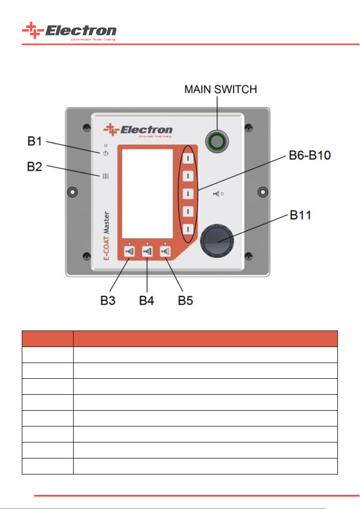
2.7. Front Panel and Input Buttons
Button Denition
B1
B2 Menu Button
B3 Automatic Program 1
B4 Automatic Program 2
B5 Automatic Program 3
B6-B10 Segment Buttons
Main Switch Main Power Switch
B11 Rotary Adjustment Knob
10
Fluidization and Vibration Motor(Only Multicolor) Active/Passive Button
Page 11

2.8. Back Panel and Connections
Back Panel Connections
CONNECTION FUNCTION
1.0 POWER IN MAIN POWER CONNECTION (100-240VAC, 50-60Hz)
1.2 Fuse 1.6A Glass Fuse Holder 1.6A
1.3 TCP/IP (Optional) TCP/IP automation serial connection RJ45 (Optimal for automatic device congurations)
1.4 GUN Gun Cable Connection
1.5 AUX Fluidization Unit/Multicolor Unit Connection
1.6 PURGE (Optional) Purge Valve Connection (Supplied with optional Purge Module)
MAIN AIR IN 5.5-7 BAR Main Pressured Air Connection (5,5-7,0 Bar, Ø8 Hose)
Nozzle Air Connection (Black Ø6 Hose)
Supplementary Air Connection (Blue Ø8 Hose)
Powder Air Connection (Red Ø8 Hose)
Earth Cable Connection
Back Panel Connection Table
Warning: AUX input lid should be closed if there is no connection.
PIN Connection
1) Phase (100-240 VAC)
2) Neutral
3) Trigger (Phase Applied-Only Automatic Mode)
PE) Grounding
11
Page 12

2.9. General Instructions
Usage Types
a. Automated Recipe Working Mode
This type of usage allows the customer to work with custom made recipes as well the three predened recipes stated below:
1. Coating on Straight Faced Materials
2. Coating on Coated Materials
3. Coating on Notched Surfaces
Predened Recipe Buttons
Predened Recipe Name High Voltage (kV) Output Current (µA)
Coating on Straight Faced Material 100 100
Coating on Coated Material 100 10
Coating on Notched Surfaces 100 22
Predened Recipe Working Parameters
12
Page 13

b. User Dened Recipe Working Mode
In this working principle, the user can save their own working parameters and change them. There can be 4500 recipes starting
from P01 to P50, three of which P01-02-03 are factory predened recipes. These predened recipes are explained in this manual.
Users can manually dene 47 different recipes of their choice.
Recipe Segment
c. Fast Purge Mode
Fast Purge mode uses the high pressured air to clean the Injector, Antistatic Coating Hose and E-GUN Coating Path. A “FastPurge”
sign will appear on the main screen of the E-COAT Master when Fast Purge mode of the device is activated. E-COAT Master Device’s
Fast Purge mode can be activated by two different ways.
a. By pressing and holding the Page Button (B2 Button) for 3 seconds.
b. By pressing and holding the “P” button on the manual E-GUN C1 gun for 3 seconds.
Fast Purge Mode Screen
Fast Purge mode’s working scenerio alters depending on the device conguration. The Fast Purge mode stays on for 10 seconds
and rinses through the hose and gun automatically If the E-COAT Master device is congured as “Auto”. On the other hand, the gun
trigger on the E-GUN C1 works as a valve trigger during the Fast Purge mode if the E-COAT Master device is congured as a manual
device (Hopper or Multicolor). The air comes out from the Purge Unit if the trigger is pressed and stop if the trigger is released.
The E-COAT Master device exits from the Fast Purge mode if the trigger is not pressed for 3 seconds or the “P” button on the back
side of the E-GUN C1 is pressed once during Fast Purge mode.
d. Remote Control with E-GUN C1
The user can change the system parameters on E-COAT Master via using the E-GUN C1. The buttons which are marked “P”, “^”
and “ˇ” are explained below
Button Function
P Recipe, Powder Ratio, Powder Air with consecutive presses - Fast Purge (via pressing 3 seconds)
v
v
Value decrease
Value increase
e. Consumable Counters
E-COAT Master is designed with consumable counters so that the use would be always aware of the materials.
You can open the counter via pressing the B2 button for two times.
13
Page 14

The user can also adjust the counters to create a warning when the consumables are about to nish or when they are nished.
See the counters on the screen below.
Consumable Counters Screen
The user can differentiate between consumables and adjust ve different consumables on the screen. The counters will warn the
user when they reach to zero if they are not reset. A “!” sign will lit and blink on the bottom of the main page when a counter has
reached to “0” and the counter is not reset by entering into the counters page for acknowledgement. The blinking “!” sign will
disappear from the screen when user enters to the counters page to acknowledge the counter alarm. The unit of the counters are
“Days”.
f. Screen Brightness Adjustment
E-COAT Master electrostatic powder paint control unit screen brightness can be adjusted by the user. The LCD screen allows the
user to change the brightness from the segment button shown below in the second part of the Main Page. Reaching to the second
part of the Main Page is from pressing the B2 button once.
Part-2 Screen Brightness Segment
The screen brightness can be adjusted between the values 0 to 10, 0 showing the lowest brightness and 10 showing the highest.
Info: E-COAT Master control unit is installed with standby mode. If the buttons are not used on the control unit or on the E-GUN, the
control unit changes the brightness level to 0. Any input while in standby mode switches the control unit to the normal mode and the brightness
becomes to the normal level
14
Page 15

3. Start Up
3.1. Installation
a. “Bare” and “H” type Device Kits Electro-Pneumatical Connections
15
Page 16

b. “M” type Device Kits Electro-Pneumatical Connections
16
Page 17

c. “A” type Device Kits Electro-Pneumatical Connections
17
Page 18

3.2. Start Up
Info: E-COAT Master Powder Coating Control unit always starts with the last used conguration preferences.
In the above “System Connections” gure, all the electrical and pneumatic connections are shown. After correctly connecting the
device, the user can press the “Main Switch” to start the control unit. The below procedure should be done at the rst Start up.
E-COAT Master should be calibrated according to the products that are going to be powder coated before the start up. Once you
are in the “Main Page” Press the B1 interface button for 5 seconds and the Congurations Page 1 will appear a. The Conguration
Pages are ve pages in total and by pressing B2 button the user can cycle through them. The user can switch to the “Main Page”
by pressing B1 button once.
Info: If the control unit is not used or a button is not pressed for 15 seconds time, the control unit automatically goes
back to the “Main Page”.
The available calibrations for the “Calibration Pages” are stated in the below table
Calibration Preferences
Code Code Info Preferences Factory Preset
0 = Automatic
C-1 Control Type Selection
1 = Manual w/ Hopper
2 = Manual w/ Multicolor
1
C-2 Gun Type
C-3 AUX output latency after trigger release (s) 0-100 10
C-4 Pneumatical Control Type
C-5 Pneumatical Flow Units
C-6 Purge Valve Opt.
C-7 Gun Cable Length (m) 5-25 5
0 = Corona
1 = Tribo
0 = Proportional
1 = Independent
0 = lt/m
1 = Nm3/h
0 = Disabled
1 = Enabled
0
0
1
0
PCF1 Min. Powder Corr. Factor (lt/m) 0 - 50 5
PCF2 Powder Output Corr. Factor 0 - 100 100
Info: Correction Factors should be adjusted from the “Correction Factors Adjustment Table” below.
18
Page 19

3.3. Operation
a. Creating and Saving a User Recipe:
Recipe Segment
After adjusting the values from the control unit, the user can save the recipe for future usage. To save the current recipe, press
and hold the segment button next to the recipe segment button for three seconds. You will see the recipe number ashing every
500ms. The user then chooses the recipe number for the current recipe. Turn the knob until the desired recipe number is selected.
Once the number is selected the recipe can be saved.
To save the recipe, press and hold the same segment button for three seconds. This time, the screen will start ashing every 200ms
for 2 seconds and the recipe will be saved successfully. If instead of pressing and holding for three seconds, the user presses the
button, the current recipe will not be saved and the screen will turn to its rst position.
b. Predened Recipe Usage
Predened Recipe Recall Buttons
Pressing the rst predened recipe on the left side calls the at surface coating application. After pressing, the screen automatically
brings the P01 recipe and the LED indicator will light up. Similarly, if the user presses the button on the middle, the control unit
brings up the P02 recipe which is the “Coating on Coated Surface”, and if the user presses the right button the “Coating on Notched
Surface”. Recipe will be recalled and the proper LED will light up.
19
Page 20

Predened Recipe Working Parameters are located below
Predened
Recipe Name
Flat Surface Application 100 100
Coating on Coating Application 100 10
Notched Surface Application 100 22
High Voltage (kV) Current (µA)
High Voltage Preferences:
There are two different methods in E-COAT Master to change the High Voltage and Gun Output Current. These are as follows:
1. Using the front panel interface of E-COAT Master
2. Using the E-GUN C1 Manual type back side interface.
As it is shown in the below gures, the values can be changed on the rst two segment buttons. Once the value
segment is selected, the user can adjust the values via rotating the knob on the device
High Voltage and Current Adjustment Segments
The adjustments set the upper limits of both the High Voltage and Current Values. The values can change while gun operation,
according to the coating application, and the type of workpiece. These values will also change according to the length between the
workpiece and the tip of the gun. Once the gun is triggered the values can be read on the same segment. The “Orange” coloured
parts show the adjusted values on the selected recipe and the “Black” coloured numbers show the real time usage values.
Info: The upper limit of the High Voltage is 100kV and the current output limit is 100µA.
Air and Powder Adjustments:
There are two different pneumatic control types of E-COAT Master powder coating device.
These are;
1. Control via the Total Air and Powder Ratio
2. Control via Independent Air Flow
Picking the rst option, the user should adjust the value in regards to the air/powder ratio. The total output air per unit time
should be calculated and the total powder per unit time should be adjusted accordingly.
20
Page 21

Main Page Air/Powder Ratio Control Segments
Picking the second option which is the Controlling via Air Flow, the user will see the below icons on the segments, Powder Transfer
Air and Assistant Air Flows will be set independently. This method is mostly used on Manual System Congurations.
Suggestion: For the best surface nishing in automatic systems, it is best to adjust the air ow with Ratio Control.
Info: Air Flows can be selected from C1-4 parameter and also can be seen as Nm
3
/h lt/min.
Info: Air Flows Control mode (as explained on installation) can be adjusted with C1-3.
The E-COAT Corona type powder gun includes High Voltage output the tip of the nozzle, powder output nozzle and nozzle air. This
nozzle air can be adjusted. It should be noted that every other nozzle types’ optimal adjustment values are different. Nozzle air
adjustment can be made from the second page of the interface from the rst segment. Like the other air adjustments the user
can also see the values in Nm3/h or lt/min.
Nozzle Air Adjustment Segment
Suggestion: As Factory Preset, for the Flat type nozzle groups the Nozzle Air Flow is set to 0,2 Nm
Deector type nozzle groups it is set to 0,5 Nm3/S.
3
/S, for the Circle type and
Correctional Factor Adjustment:
On the E-COAT Master conguration screen, C2-1 and C2-2 includes two different powder ratio correction factors. One of the
correction factors is to adjust the minimum powder level and the other one is to synchronize the system if there is more than one
control unit available for use. The rst parameter adjustment is 4.0 Nm3/S of total air and the powder ratio is %0 while there is
10gr of powder output. This ensures a better curve on the powder ratio control graphic and removes the “dull” zone. The second
parameter is needed because of the multiple gun usage and the different sizes of the gun hoses in the automatic systems. C2-2
removes the possibility of different ow output rates on different guns in the same system thus a better surface nish.
The user should follow the procedure below when adjusting the correction factors.
The user should follow the procedure below when adjusting the correction factors.
1. If the Air Control mode is not on Ratio Control type, the device should be changed to Ratio control. Press and hold the B1
interface button on the Main Page for 5 consecutive seconds and reach the Calibration Pages. Adjust the C1-3 parameter to 0
(zero) then press B1 button again to get back to the Main Page.
2. On the Main page the Total Air Flow should be adjusted to 4.0 Nm3/h or 67 lt/min.
3. Press and hold the B1 interface button on the main page and reach the Calibration page again.
4. Press the B2 interface button and reach the Calibration Page -2 where C2-1 and C2-2 parameters are located. You will need
a lter type powder bag to measure the powder weight output from the spray gun.
5. Put the powder bag at the tip of the gun.
6. Press the trigger for a whole 60 seconds and stop the trigger.
7. Release the bag from the tip of the gun and weight it.
8. The ideal weight should be between 10g and 15g, if the weight is below 10g increase the C2-1 parameter and if it is more than
15g decrease it.
21
Page 22

PCF-1 Correctional Factor Reference Table
Gun Maximum Powder Output Correction Factor PCF1
Before Correction After Correction
1 PCF1 = 5 lt/min 22 gr. PCF1 = 2 lt/min 13 gr.
2 PCF1 = 5 lt/min 14 gr. PCF1 = 5 lt/min 14 gr.
3 PCF1 = 5 lt/min 3 gr. PCF1 = 15 lt/min 12 gr.
After adjusting the PCF1 Minimum Powder Output Correction Factor, the user can adjust the PCF2 Powder Output Equalization
Factor (%) procedure. This procedure is as follows:
1. On the Main Page, the Total Air Flow should be adjusted to 4,0Nm3/h or 67lt/min.
2. Also the Powder Ration should be adjusted to %80.
3. While on Main Page, Press and hold the B1 interface button for ve (5) seconds to reach the Calibration Page.
After this step, you must use a lter type powder bag to measure the powder output in one (1) minute.
4. Put the powder bag at the tip of the gun.
Info: Before putting the bag on, measure the weight of the bag to make a better calculation. Press the trigger for a whole 60 seconds and
stop the trigger.
5. Press the trigger for a whole 60 seconds and stop the trigger.
6. Release the bag from the tip of the gun and weight it.
7. After measuring all the automatic guns’ output, proceed to the next step.
8. Make the below calculation for all the automatic guns and get the necessary C-9 parameter.
Minimum Powder Output (g/mn)
PCF2
gun
Measured Powder Output
9. Input the calculated parameter on the control unit.
After the input procedure, there will be a similar table like below
gun
(g/mn)
PCF-2 Correctional Factor Reference Table
Gun Minimum Powder Output Correction Factor PCF-2
Before Correction After Correction
1 PCF2 = %100 220 gr. PCF2 = %100 220 gr.
2 PCF2 = %100 255 gr. PCF2 = %86 220 gr.
X 100
22
3 PCF2 = %100 275 gr. PCF2 = %80 220 gr.
Page 23

Double-Triggering and Sub-Recipe System:
The E-COAT Master controller unit gives the opportunity to jump between two recipes to its users. The user can switch between
any two recipes in a blink of an eye without any need to reach the main controller interface during operation. A recipe can be
switched to its sub-recipe such as a “complex parts” recipe when needed. Also, similarly, the sub-recipe can be switched back to
its main one just by double-triggering again.
The sub-recipe of each main recipe can be set in the second segment on the second page of the controller. The controller jumps
to the sub-recipe desired when “double-triggered” on the manual gun during operation after setting the sub-recipe of any main
recipe and saving it.
other one even though the manual gun trigger is double-pressed. The recipe should be saved again into a desired number after
any change is made to the double-triggering recipe number on the second page. The main reason for re-save is same as other
parameter changes where the user goes out of any saved recipe by changing a parameter which is already saved in the main recipe
just like other parameters in the main screen.
working with the sub-recipe.
TCP/IP Communication and Master/Slave Option:
E-COAT Master controller unit has an optional connection to an automation system or to any other E-COAT Master device. In this
case, the parameters of the controller can be controlled by any TCP/IP based automation system or by any other E-COAT Master
device which is set as a “Master” in its network settings. Similary, The E-COAT Master Device can be set as a “Master” to be able
to control other E-COAT Master devices’ parameters where the other devices are set as “Slave” in their network settings. The
NOTE: The E-COAT Master device does not include the Network Connector on itself as default. The “E-COAT ETHERNET SOCKET
MODULE WITH PATCH CABLE” with order code “B07 140513” should be ordered as an optional part for TCP/IP Network communication
if needed.
arameters”.
Code Info Preferences Factory Preset
IP Address IP Address of the device itself. 192.168.0.110
Subnet Mask
Gateway Gateway of the Network which the device is connected 255.255.255.0
Master/Slave
Subnet Mask of the Network which the device is con-
nected.
Master = The device is set as a commander in a network
where the operational parameters of this device is sent
to other devices.
Slave = The device is set as a listener in a network
where the operational parameters of the device is cop-
ied from a desired master device.
Valid only when the device is set as a “Slave” in the
192.168.0.1
Slave
Master IP
Network
network. The operational parameters of the device is
copied from the Master device of which the IP parame-
ters is pointed in this setting.
OFF = Network Communication Disabled
ON = Network Communication Enabled
192.168.0.100
OFF
23
Page 24

3.4. Trigger
When triggered the Electrostatic Powder Application Control unit will start applying static electricity to the sprayed powder paint.
The trigger conguration can be done in two different ways.
1. Using the Gun Trigger. (In a manual conguration)
2. If the POWER IN socket on the control unit is fed from the number three (3) meaning the terminal control unit’s POWER IN
socket number 3 feed, starting up a precongured equipment will be done via pressing the B1 interface button. If the
control unit is active, this led will be lit. If the number three (3) cable socket is fed the powder paint will be blown it
will be statically loaded.
Warning: The 1.0 coded POWER IN socket’s inner connections and the fuse connections at the other end should be done by the
ELECTRON technicians at the installation. Electron does not accept any responsibility for the possible damage if the equipment is altered or used
before installation.
C1 Parameter B1 Button Status System Operation
The device is ready to be triggerred. The device will be
Enabled
0 = Automatic
Disabled
triggerred when mains phase voltage is applied to pin #3 of
POWER IN socket.
The device is disabled to be triggerred. The device will not
be triggerred even if phase voltage is applied to pin #3 of
POWER IN socket.
Enabled
1 = Manual (w/or w/out hopper)
Disabled
Enabled
2 = Manual (Multicolor/Stirrer)
Disabled
B1 Button Function Table
Pressing the gun trigger on the manual gun or using the electrical trigger on the automatic gun, if the high voltage and the air/powder ratio
adjustments are done, the guns will be spraying statically loaded powder paint. The user can observe this occurrence from the green lit led
(D-T marked) in front of the control unit.
3.5.
Fluidization
AUX socket is powered continously.
AUX socket is disabled.
AUX socket is powered depending on triggering. AUX is
kept powered during triggering and turns off after the time
dened in parameter C3 following trigger release.
AUX socket is disabled.
Fluizidation Control Panel
A “Fluidization Control Panel” is placed on the mobile device carrier for the operator to easily adjust the uidization pressure
for H type devices with hopper or M type devices with box uidizied suction tubes. Turning the regulator knob counter-clockwise
will degrease or clockwise will increase the applied pressure to the uidization nozzle in the system. The green and red areas are
signed to indicate the approximate operating pressure values for the uidization air. The uidization will start in parallel with
the vibration motor when the device is triggered if the button is enabled for “M” type multicolor sets. The uidization will be
activated all the time when the device is energized and the button is enabled for “H” type hopper sets.
24
Page 25

4. Cleaning and Maintenance
4.1. Cleaning
4.1.1. Gun Body Cleaning
Daily:
• Clean the body of the gun with pressurized air and a clean towel.
• Remove the nozzle torque nut.
• Remove the gun nozzle and the electrode and clean the gun with pressurized air.
Weekly:
• Remove the powder paint hose.
• Clean the powder paint input of the gun with pressurized air.
• Clean the powder paint hose starting from the injector.
4.1.2. Nozzle Cleaning
Every other shift or at the end of a working day:
• Remove the nozzle torque nut.
• Remove the gun nozzle and clean both the electrode and the nozzle.
• Clean all the powder thoroughly. Never try to scratch the paint with a strong material.
Weekly:
4. Check the nozzle group for scratches. Change the nozzle group using the spare parts list if needed.
4.1.3. Maintenance
E-GUN C1 type manual and C3 type automatic coating guns is designed to be maintained with minimum effort.
• Clean the powder gun body with a clean towel.
• Make an eye check on the gun cable and input hoses.
• Change the powder and pneumatic hoses if needed.
Part Change
The user can only change the consumables of the gun and some of the E-GUN coating gun parts.
Note: Operations like Changing the Cascade, Trigger mechanism or Gun Cable can only be done by an ELECTRON® approved personnel.
5. Troubleshooting
Troubleshoot Code Explanation Suggestions
• Check the gun cables for a possible tearing
kV and µA segments fully blinking “0” Feedback Signal Failure
• Check the connection between the gun Cascade and the Socket Group inside the gun.
• Check Cascade for Mulfunction.
Error Codes
The failures which are mentioned above can be observed from the “kV “titled segment in the front panel of the device. The fault
should be xed before starting the device and the device should be shut down and start up from the MAIN SWITCH.
The other faults in the user interface are explained below.
25
Page 26
Failure
Powder Paint is being blown from the
gun but the paint doesn’t hold on the
material. (No High Voltage Output)
The gun trigger is working and the High
Voltage is working but there is no pow-
der output.
There isn’t any output High Voltage or
Powder Output.
The interface buttons are not working as
intended.
Possible Failure
Reason
1. The material is not earthed
2. The kV parameter is set to 0
3. The signal from the gun does not
reach to the Cascade.
1. Blockage in the powder route
2. Tearing or disconnection between the
injector and the control unit.
1. Gun cable is disconnected.
2. Gun cable is damaged
3. Short Circuit or damage in the Gun
Trigger grouping
1. The Control Unit front panel membrane has a short circuit or damaged.
2. The Control Unit is not correctly
congured.
Solution
1. Earth the material or improve the
grounding.
2. Set the kV parameter above 0
3. Check the connection between the
gun Cascade and the Socket Group for a
possible short circuit inside the gun.
1. Remove the blockage in the powder
route.
2. Change the Air or Powder Ratio other
than 0 on the control unit.
3. Remove the blockage or x the disconnection.
1. Plug the cable.
2. Check for the damage or change the
cable
3. Check the grouping for short circuit or
damage and change the trigger group if
needed.
1. Change the keypad of the membrane.
2. Check the entire conguration of the
Control Unit and redo the conguration
if needed.
The rotary Knob is not changing any
values on the screen.
Troubleshoot Code Explanation Suggestions
There isn’t any high voltage and the
control unit is ashing with kV and µA
signs.
Powder Paint is being blown from the
gun but the paint doesn’t hold on the
material (No High Voltage Output)
Powder Paint is being blown from the
gun but the paint doesn’t hold on the
material (No High Voltage Output)
Pressing the trigger doesn’t start the
control unit (The LED in front of the
control unit is not lit)
1. The segment is not chosen.
2. The Knob is damaged.
1. Gun cable is not connected.
2. The gun cable is connected but not
well xed to the socket
3. Gun cable is damaged.
4. Cascade is damaged.
1. The material is not earthed
2. the kV or µA parameter is set to 0
3. The signal from the gun does not
reach to the Cascade.
1. Blockage in the powder route
2. The Air or Powder Ratio segment is
set to 0
3. Tearing or disconnection between the
injector and the control unit.
4. If the preferences are adjusted in
a well manner, the proportional valve
inside the gun might be damaged
1. Gun trigger is damaged 1. Consult and ELECTRON expert
1. Please select the segment that you
want to change.
2. Change the Rotary Knob.
1. Connect the gun hose.
2. Fix the cable to the socket.
3. Consult an ELECTRON expert.
1. Earth the material or improve the
grounding.
2. Set the kV or µA parameter above 0.
3. Consult an ELECTRON expert.
1. Blockage in the powder route
2. The Air or Powder Ratio segment is
set to 0
3. Tearing or disconnection between the
injector and the control unit.
4. Consult and ELECTRON expert
Parameters at the installation are con-
gured but the powder pattern is not
well.
26
1. Teon bushing in the injector’s life
cycle is ended.
2. Nozzle life cycle is ended.
3. Pneumatic hoses are damaged/broken
or plugged.
4. The air channels are plugged.
5. Injector jet’s life cycle is ended
1. Change the Teon bushing.
2. Change the nozzle
3. Fix the pneumatic hoses or change
them if needed.
4. Clean the injector and the lters.
Change any necessary parts.
5. Change the injector jet.
Page 27

6. Parts and Accessories
3 43 4
21
Product # Product Name Order Code
1 E-COAT Master Automatic Bare Kit A06 ECA01A
2 E-COAT Master Manual Bare Kit A06 ECM01B
3 E-COAT Master H A06 ECM01H
4 E-COAT Master M A06 ECM01M
27
Page 28

Control Unit Type Order Code
E-COAT MASTER CONTROL UNIT B07 ECMU01
Part No Part Name Order Code Qty
1 E-COAT CONTROL UNIT FRAME C05 EC5002
2 E-COAT MASTER FRONT MEMBRANE K06 LG5000
3 E-COAT CONTROL UNIT CASE C05 EC5001
4 Ø22 STAINLESS POWER LED E10 ONPOW01 1
5 INCREMENTAL ENCODER B07 IENC01 1
Order Code Part Name Wearing Part
B07 POWER01 E-COAT MANUAL DEVICES POWER CABLE (3m) *
1
1
1
B07 POWER02 E-COAT AUTOMATIC DEVICES POWER CABLE (4 m) *
B07 140513 E-COAT ETHERNET SOCKET MODULE WITH PATCH CABLE N/A
28
Page 29

Part No Part Name Order Code Qty
1 E-COAT MASTER BACK SHEET METAL C05 EC5004 1
2 RS-50-24 24 V DC SMPS E09 SMPS50 1
3 E-COAT FRONT/BACK SEALING H02 500001 1
4 E-COAT CONTROL UNIT CASE C05 EC5001 1
5 E-COAT MASTER MAINBOARD E09 500001 1
6 E-COAT MASTER GRAPHIC CARD E09 500002 1
7 E-COAT MASTER FRONT ALUMINUM SHEET C05 EC5003 1
8 E-COAT FRONT/BACK SEALING H02 500001 1
9 E-COAT MASTER FRONT MEMBRANE K06 LG5000 1
10 E-COAT CONTROL UNIT FRAME C05 EC5002 1
11 M4X15 YSB SCREW H01 1010415 4
12 M6X16 E-COAT CONTROL UNIT FRAME NUT H01 1120616 2
13 PROPORTIONAL VALVE G05 VY1B00 3
14 E-COAT PNEUMATIC VALVE PLATE T01 9000020 1
15 VALVE SEALING EPDM 3X45X119 MM H02 345119 1
29
Page 30

Part No Part Name Order Code Qty
1 SHURTER IP68 FUSE E10 CAMYUV2 1
2 GROUNDING NUT (M5X20) H01 SOM005 1
3 GSA 3000 A TYPE MALE VALVE SOCKET E19 GSA3000 1
4 M4X15 YSB SCREW H01 1010415 8
5 RJ 45 ETHERNET PANEL E19 140513 1
6 RD24 7 PIN CONNECTOR E19 RD24D7 1
7 RD24 4 PIN FEMALE CONNECTOR E19 RD24D4 1
8 RD24 4 PIN MALE CONNECTOR E19 RD24E4-2 1
9 M3X10 YSB H01 1010310 6
10 M4X10 YSB H01 1010410 4
11 5X20A 1,5A GLASS FUSE E10 CAM1,5 1
30
12 PIPE STRAIGHT 1/8”-Ø8 PNEUMATIC MALE G05 KQ2S08 3
13 PIPE STRAIGHT 1/8”-Ø6 PNEUMATIC MALE G05 AKH06A 1
14 SILENCER SINTER G05 AN1001 1
Page 31

ACCESSORY TYPE ORDER CODE PART #
E-COAT Platform Mounting Kit B07 ECT004 1
E-COAT Wall Mounting Kit B07 ECT003 2
E-COAT Single Stand Kit B07 ECT005 3
E-COAT Mobile Stand Kit B07 ECT001 4
E-COAT MultiColor Kit B07 ECT002 5
31
Page 32

Product # ORDER CODE PART NAME WEARING PART
1 B07 EGC100 E-GUN C1 MANUAL POWDER COATING GUN N/A
32
Page 33

33
Page 34

Part # Order Code Part Name Wearing Part
1
1.1 C07 520015 E-GUN C1/C2 BACK COVER OUTER LID (CONDUCTIVE) N/A
1.2.1** B07 LG5005 E-GUN C1 BACK LID KEYPAD AND KEY COVER N/A
1.2.2** K06 LG5004 E-GUN C2 BACK LID KEYLESS COVER N/A
1.3 H01 1010308 M3X8 YSB BOLT N/A
1.4 H01 10303065 3X6,5 SCREW for PLASTIC N/A
1.5 C07 520016 E-GUN C1/C2 BACK COVER INNER LID N/A
1.6 C07 520017 E-GUN C1/C2 BACK COVER INNER LID GASKET N/A
2 C07 520019 E-GUN C1/C2 CASCADE ISOLATION GASKET N/A
3 C07 520009 E-GUN C1/C2 POWDER PIPE ELBOW *
4 B07 EGCN01 E-GUN CASCADE N/A
5 B07 EC0001 E-GUN C1/C2 GUN BODY ASSEMBLY (COMPLETE) N/A
5.1 C07 520001 E-GUN C1/C2 GUN BODY MAIN PART N/A
5.2 B07 520007 E-GUN NOZZLE AIR FILTER UNIT N/A
6 B07 EC0002 E-GUN C1/C2 TOP POWDER PIPE ASSEMBLY (COMPLETE) *
6.1 C07 520010 E-GUN C1/C2 TOP POWDER PIPE *
6.2 H02 015200 O-RING Ø15X2 NBR70 N/A
7 B07 EC0003 E-GUN C1/C2 HANDLE ASSEMBLY (COMPLETE) N/A
7.1 C07 520002 E-GUN C1/C2 HANDLE BODY (CONDUCTIVE) N/A
7.2 G05 RPD0605 CONNECTOR FEMALE STRAIGHT HOSE Ø6-M5 N/A
7.3 H01 1010308 M3X8 YSB BOLT N/A
8 C07 520011 E-GUN C1/C2 BOTTOM POWDER PIPE *
9 C07 520018 E-GUN HOSE CONNECTOR SPRING N/A
10 C07 520003 E-GUN HOSE CONNECTOR LOCKING RING N/A
11 B07 528005 E-GUN C1/C2 GUN CABLE (5m) N/A
12 B07 EC0004 E-GUN HOSE CONNECTOR ASSEMBLY (COMPLETE) N/A
12.1 C07 520004 E-GUN HOSE CONNECTOR BODY N/A
12.2 H02 012150 O-RING Ø12X1,5 SILICONE N/A
13 C07 520012 E-GUN C1/C2 TRIGGER BODY N/A
14 B07 LG5006 E-GUN C1/C2 TRIGGER KEYPAD N/A
15 H01 1050310 E-GUN C1/C2 TRIGGER BODY SET-SCREW N/A
16 B07 524002 E-GUN NOZZLE TIGHTENING NUT N/A
17 PLEASE CHECK NOZZLE TYPES SELECTION LIST
B07 BC0001
E-GUN C1 BACK COVER ASSEMBLY (COMPLETE) N/A
34
**Part #1.2.1 or #1.2.2 Manual Gun Type (C1 or C2) should be considered before ordering.
Page 35

PART # ORDER CODE PART NAME
1 B07 EGC300 E-GUN C3 AUTOMATIC POWDER COATING GUN (COMPLETE) N/A
WEARING
PART
35
Page 36

36
Page 37

Part # Order Code Part Name Wearing Part
1 B07 EC0004 E-GUN HOSE CONNECTOR ASSEMBLY (COMPLETE) N/A
1.1 C07 520004 E-GUN HOSE CONNECTOR BODY N/A
1.2 H02 012150 O-RING Ø12X1,5 SILICONE N/A
2 B07 528012 E-GUN C3 GUN CABLE (12m) N/A
3 C07 520003 E-GUN HOSE CONNECTOR LOCKING RING N/A
4 C07 520018 E-GUN HOSE CONNECTOR SPRING N/A
5 C07 521020 E-GUN C3 QUICK HOSE CONNECTOR HOLDER N/A
6 B07 EC0005 E-GUN C3 ALUMINUM CLAMP ASSEMBLY (COMPLETE) N/A
6.1 C07 522010 E-GUN C3 ALUMINUM CLAMP ADAPTER N/A
6.2 H01 1040520 M5X20 ALLEN BOLT N/A
7 B07 EC0006 E-GUN C3 ALUMINUM BACK COVER ASSEMBLY (COMPLETE) N/A
7.1 C07 522011 E-GUN C3 ALUMINUM BACK COVER N/A
7.2 H01 1040560 M6X60 HALF THREAD PLATED ALLEN BOLT N/A
7.3 G05 RPD060501 CONNECTOR MALE STRAIGHT HOSE Q6-M5 INNER ALLEN KEYED N/A
7.4 E19 M12E04 M12-A 4 PIN PANEL TYPE CABLE MALE CONNECTOR N/A
7.5 H02 014150 O-RING Ø14X1,5 SILICONE N/A
8 B07 EC0007 E-GUN C3 BODY BACK PART ASSEMBLY (COMPLETE) N/A
8.1 C07 521005 E-GUN C3 BODY BACK PART N/A
8.2 H02 035150 O-RING Ø35X1,5 NBR70 N/A
8.3 C07 520005 E-GUN NOZZLE AIR M5-Ø6 HOSE CONNECTOR N/A
8.4 H01 1120515 M5X15 ALLEN BOLT N/A
9 B07 EC0008 E-GUN C3 INNER LID ASSEMBLY (COMPLETE) N/A
9.1 C07 522012 E-GUN C3 INNER ASSEMBLY ALUMINUM HOLDER N/A
9.2 C07 521006 E-GUN C3 INNER ASSEMBLY FRONT BODY LID N/A
9.3 H01 1040570 M5X70 HALF THREAD PLATED ALLEN BOLT N/A
10 B07 EGCN01 E-GUN CASCADE N/A
11 B07 EC0009 E-GUN C3 POWDER PIPE ASSEMBLY (COMPLETE) N/A
11.1 C07 521001 E-GUN C3 POWDER PIPE N/A
11.2 H02 015200 O-RING Ø15X2 NBR70 N/A
12 B07 EC0011 E-GUN C3 BODY FRONT PART ASSEMBLY (COMPLETE) N/A
12.1 C07 521004 E-GUN C3 BODY FRONT PART N/A
12.2 B07 520007 E-GUN NOZZLE AIR FILTER UNIT N/A
13 B07 524002 E-GUN NOZZLE TIGHTENING NUT N/A
14 PLEASE CHECK NOZZLE TYPES SELECTION LISTS
37
Page 38

Part # Part Name Order Code Wearing Part
1
2
GUN CABLE EXTENSION KIT (5 m) B07 EXT005 N/A
GUN CABLE EXTENSION KIT (10 m) B07 EXT006 N/A
Part # Part Name Order Code Wearing Part
1
11X16 POWDER HOSE w/ DOUBLE CARBON DISCHARGE LINES
(ORDER IN METERS)
H08 EH1116 N/A
Product # Part Name Order Code CONSUMABLE
1 E-COAT EARTHING CABLE (3 m) B07 ECK506 N/A
38
Page 39

Part #Order
Code
1 B07 RCA001 E-GUN C3 COMPOSITE ARM W/ HOSE EXTENDER (COMPLETE) N/A
1.1 C07 521009 E-GUN C3 COMPOSITE GUN ARM N/A
1.2 B07 RCA002 E-GUN C3 HOSE EXTENDER FOR COMPOSITE ARM SET *
1.3 C07 521013 E-GUN C3 COMPOSITE GUN ARM BACK COVER N/A
Part Name Wearing Part
WEARING
PART
39
Page 40

Part # Order Code Part Name Wearing Part
1 B07 FCR001 E-GUN C3 FAST CORONA DE-IONIZER UNIT (COMPLETE) N/A
1.1 H01 6020406 E-GUN C3 FAST CORONA UNIT SPACER SET-4X6 SETSKUR SCREW N/A
1.2 C07 527004 E-GUN C3 FAST CORONA UNIT MOUNTING BOLT N/A
1.3 C07 527001 E-GUN C3 FAST CORONA UNIT SPACER N/A
1.4 C07 527003 E-GUN FAST CORONA UNIT CHARGE COLLECTOR N/A
40
Page 41

Part # Order Code Part Name Wearing Part
1 B07 FCR002 E-GUN C1/C2 FAST CORONA DE-IONIZER UNIT (COMPLETE) N/A
1.1 H01 1010315 M3X15 YSB BOLT N/A
1.2 C07 527002 E-GUN C1/C2 FAST CORONA UNIT BACK COVER CONNECTOR N/A
1.3 C07 527005 E-GUN C1/C2 FAST CORONA UNIT SPACER N/A
1.4 C07 527003 E-GUN FAST CORONA UNIT CHARGE COLLECTOR N/A
41
Page 42

Part # Order Code Part Name Wearing Part
1 B07 EXT001 E-GUN NOZZLE EXTENSION KIT-STRAIGHT-150mm (COMPLETE) N/A
1.1 C07 524003 E-GUN Ø35 CARBON RING *
1.2 B07 524004 E-GUN ELECTRODE BODY *
1.3 C07 525003 E-GUN NOZZLE EXTENSION HOSE-STRAIGHT-150mm N/A
1.4 C07 525001 E-GUN ELECTRODE ISOLATOR EXTENSION-STRAIGHT-150mm N/A
1.5 H02 018150 E-GUN EXTENSION NOZZLE 18x1,5 O-RING N/A
1.6 C07 524001 E-GUN FLAT TYPE NOZZLES CONICAL ISOLATOR *
1.7 C07 525004 E-GUN EXTENSION NOZZLE-FLAT *
1.8
42
H02 ORG3015 O-RING Ø30X1,5 NBR70 *
Page 43

Part # Order Code Part Name Wearing Part
1 B07 EXT002 E-GUN NOZZLE EXTENSION KIT-STRAIGHT-250mm (COMPLETE) N/A
1.1 C07 524003 E-GUN Ø35 CARBON RING *
1.2 B07 524004 E-GUN ELECTRODE BODY *
1.3 C07 525006 E-GUN NOZZLE EXTENSION HOSE-STRAIGHT-250mm N/A
1.4 E-GUN ELECTRODE ISOLATOR EXTENSION-STRAIGHT-250mm N/A
1.5 H02 018150 E-GUN EXTENSION NOZZLE 18x1,5 O-RING N/A
1.6 C07 524001 E-GUN FLAT type NOZZLES CONICAL ISOLATOR *
1.7 C07 525004 E-GUN EXTENSION NOZZLE-FLAT *
1.8 H02 ORG3015 O-RING Ø30X1,5 NBR70
C07 525005
*
43
Page 44

Part # Order Code Part Name Wearing Part
1 B07 EXT007 E-GUN NOZZLE EXTENSION KIT-STRAIGHT-400mm (COMPLETE) N/A
1.1 C07 524003 E-GUN Ø35 CARBON RING *
1.2 B07 524004 E-GUN ELECTRODE BODY *
1.3 C07 525011 E-GUN NOZZLE EXTENSION HOSE-STRAIGHT-400mm N/A
1.4 C07 525012 E-GUN ELECTRODE ISOLATOR EXTENSION-STRAIGHT-400mm N/A
1.5 H02 018150 E-GUN EXTENSION NOZZLE 18x1,5 O-RING N/A
1.6 C07 524001 E-GUN FLAT type NOZZLES CONICAL ISOLATOR *
1.7 C07 525004 E-GUN EXTENSION NOZZLE-FLAT *
1.8 H02 ORG3015 O-RING Ø30X1,5 NBR70 *
44
Page 45

Part # Order Code Part Name Wearing Part
1 B07 EXT003 E-GUN NOZZLE EXTENSION KIT-45 degree (COMPLETE) N/A
1.1 C07 524003 E-GUN Ø35 CARBON RING *
1.2 B07 524004 E-GUN ELECTRODE BODY *
1.3 C07 525007 E-GUN ELECTRODE ISOLATOR EXTENSION-45 degree N/A
1.4 C07 524001 E-GUN FLAT type NOZZLES CONICAL ISOLATOR *
1.5 C07 525008 E-GUN NOZZLE EXTENSION HOSE-45degree N/A
1.6 H02 018150 E-GUN EXTENSION NOZZLE 18x1,5 O-RING N/A
1.7 C07 525004 E-GUN EXTENSION NOZZLE-FLAT *
1.8
H02 ORG3015 O-RING Ø30X1,5 NBR70
*
45
Page 46

Part # Order Code Part Name Wearing Part
1 B07 EXT004 E-GUN NOZZLE EXTENSION KIT-90 degree (COMPLETE) N/A
1.1 C07 524003 E-GUN Ø35 CARBON RING *
1.2 B07 524004 E-GUN ELECTRODE BODY *
1.3 C07 524001 E-GUN FLAT type NOZZLES CONICAL ISOLATOR *
1.4 C07 525010 E-GUN ELECTRODE ISOLATOR EXTENSION-90 degree N/A
1.5 C07 525009 E-GUN NOZZLE EXTENSION HOSE-90 degree N/A
1.6 H02 018150 E-GUN EXTENSION NOZZLE 18x1,5 O-RING N/A
1.7 C07 525004 E-GUN EXTENSION NOZZLE-FLAT *
46
1.8
H02 ORG3015
O-RING Ø30X1,5 NBR70 *
Page 47

Part # Order Code Part Name Wearing Part
1 B07 524000 E-GUN FLAT TYPE ELECTRODE ASSEMBLY (COMPLETE) N/A
2 B07 523000 E-GUN DEFLECTOR TYPE ELECTRODE ASSEMBLY (COMPLETE) N/A
3 B07 524001 E-GUN FLAT TYPE NOZZLE (COMPLETE) N/A
4 B07 523001 E-GUN DEFLECTOR TYPE NOZZLE (COMPLETE) N/A
47
Page 48
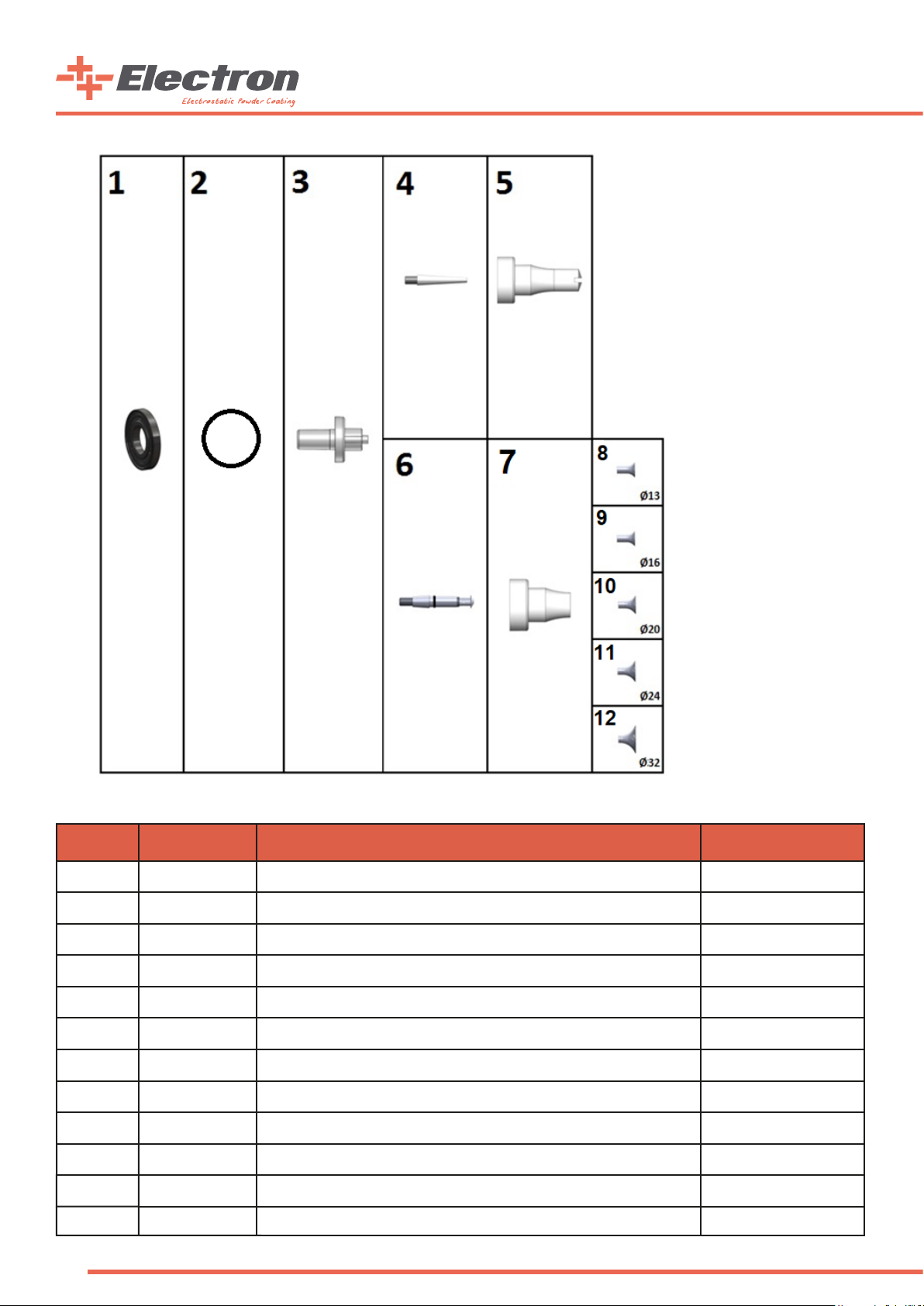
Part # Order Code Part Name Wearing Part
1 C07 524003 E-GUN Ø35 CARBON RING *
2 *
3
4 C07 524001 E-GUN FLAT type NOZZLES CONICAL ISOLATOR *
5 C07 524005 E-GUN FLAT NOZZLE *
6 B07 524502 E-GUN DEFLECTOR type NOZZLES SHAFT ASSEMBLY *
7 C07 523003 E-GUN DEFLECTOR NOZZLE *
8 C07 523013 E-GUN Ø13 DEFLECTOR *
9 C07 523016 E-GUN Ø16 DEFLECTOR *
10 C07 523020 E-GUN Ø20 DEFLECTOR *
11 C07 523024 E-GUN Ø24 DEFLECTOR *
12
48
H02 ORG3015
B07 524004
C07 523032
O-RING Ø30X1,5 NBR70
*
E-GUN ELECTRODE BODY
E-GUN Ø32 DEFLECTOR
*
Page 49

Part # Order Code Part Name
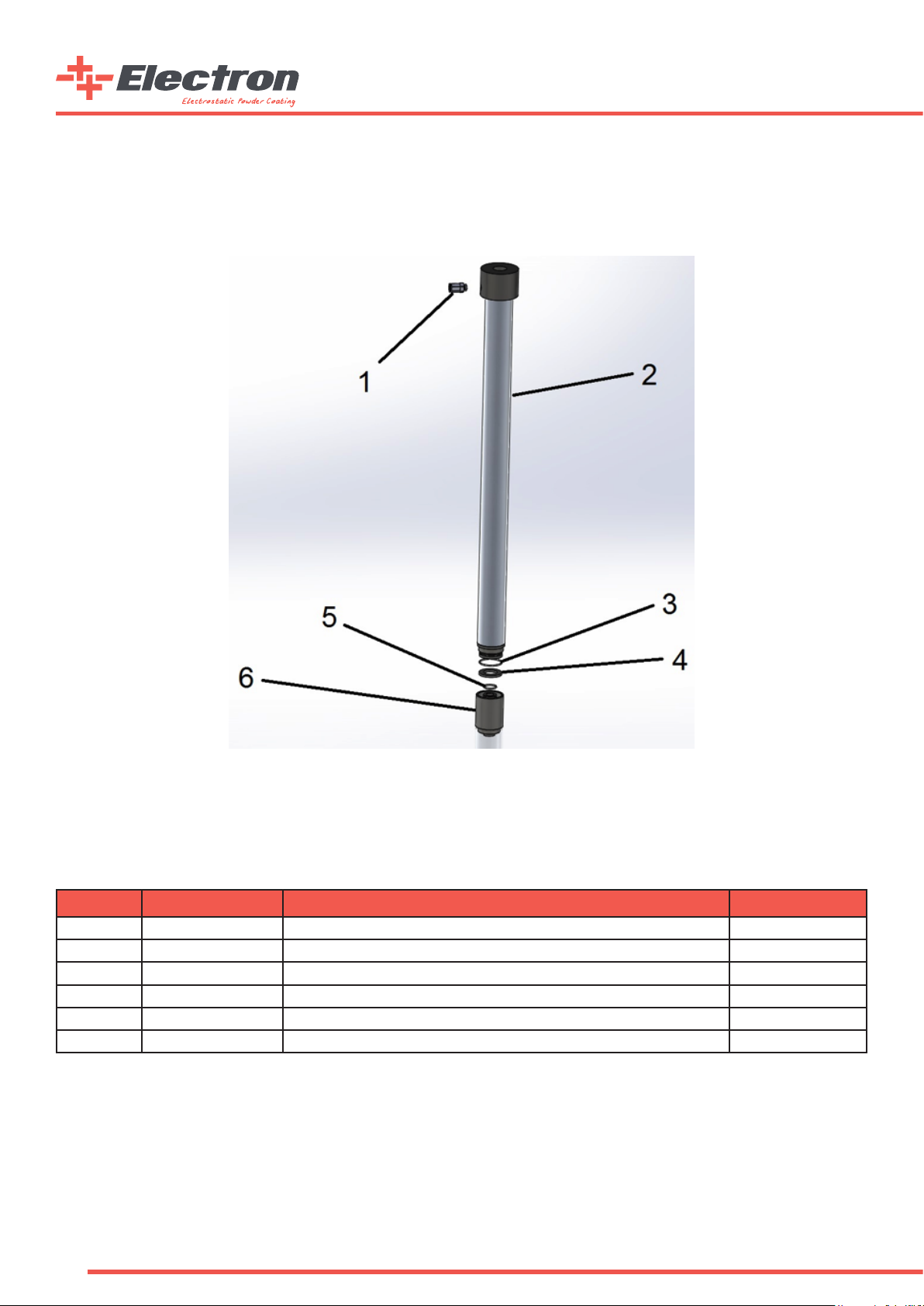
1 B07 FEEDV2 E-FEED V2 POWDER INJECTOR (COMPLETE)
2 G05 QK0002 QUICK CONNECTOR w/ SPRING 8X6mm (016-OS5)
49
Page 50

50
Page 51

Part Order Code Part Name Wearing Part
1 B07 ENJ001 E-FEED V2 MAIN AIR FILTER MODULE (COMPLETE) N/A
1.1 B07 ENJ003 E-FEED V2 FEMALE QUICK CONNECTOR ADAPTOR W/ O-RING N/A
1.1.1 C07 540008 E-FEED V2 FEMALE QUICK CONNECTOR ADAPTOR N/A
1.1.2 H02 0951501 O-RING Ø9,5X1,5 NBR N/A
1.2 C07 540009 INJECTOR SINTERED FILTER *
1.3 C07 540007 1/8" INJECTOR FILTER HOUSING (RED) N/A
2 B07 ENJ002 E-FEED V2 SUPPLEMENTARY AIR FILTER MODULE (COMPLETE) N/A
2.1 B07 ENJ003 E-FEED V2 FEMALE QUICK CONNECTOR ADAPTOR W/ O-RING N/A
2.1.1 C07 540008 E-FEED V2 FEMALE QUICK CONNECTOR ADAPTOR N/A
2.1.2 H02 0951501 O-RING Ø9,5X1,5 NBR N/A
2.2 C07 540009 INJECTOR SINTERED FILTER *
2.3 C07 540006 1/8" INJECTOR FILTER HOUSING (BLUE) N/A
3 B07 ENJ004 E-FEED V2 INJECTOR NOZZLE CAP W/ O-RING (COMPLETE) N/A
3.1 C07 540003 E-FEED V2 INJECTOR NOZZLE CAP N/A
3.2 H02 0090100 E-FEED V2 INJECTOR NOZZLE CAP O-RING (9X1) N/A
4 C07 540002 E-FEED V2 INJECTOR NOZZLE *
5 B07 ENJ005 E-FEED V2 INJECTOR MAIN BODY W/ O-RING (COMPLETE) N/A
5.1 C07 540001 E-FEED V2 INJECTOR MAIN BODY N/A
5.2 H02 016201 ORING Ø16X2 SILICONE (YELLOW) *
6 B07 540000 E-FEED V2 TEFLON BUSHING *
7 B07 ENJ006
7.1 H02 0130200 E-FEED V2 INJECTOR HOSE ADAPTOR O-RING SILICONE (13X2) N/A
7.2 C07 540004 E-FEED V2 INJECTOR HOSE ADAPTOR (CONDUCTIVE) N/A
8 C07 540005 E-FEED V2 INJECTOR HOSE ADAPTOR TIGHTENING NUT N/A
E-FEED V2 INJECTOR HOSE ADAPTOR (CONDUCTIVE) W/ O-RING
(COMPLETE)
*
51
Page 52
Order Code Part Name
B07 PURGE01 FastPurge™ Module
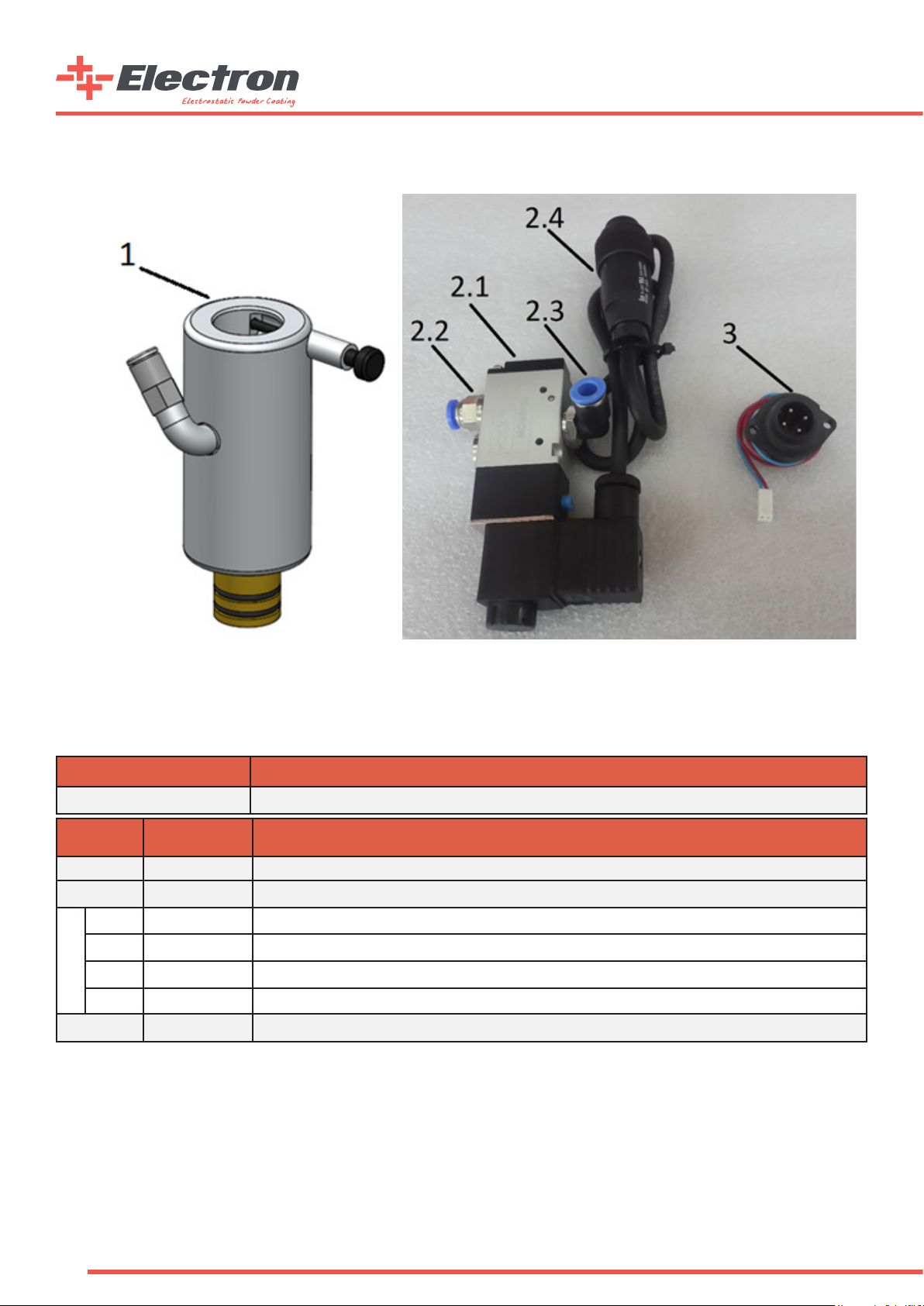
Part # Order Code Part Name
1 B07 542000 FastPurge™ MAIN BODY - (COMPLETE)
2 B07 EC0019 FastPurge™ VALVE(COMPLETE)
2.1 G05 EF32M8C ¼” 3/2 WAY VALVE WITH ATEX COIL
2.2 G05 RR0148 PNEUMATICAL CONNECTOR STRAIGHT 1/4”-Ø8 MALE
2.3 G05 RDD148 PNEUMATICAL ROTATING ELBOW 1/4”-Ø8 MALE
2.4 B07 ECK511 FastPurge™ VALVE CABLE SET
3 B07 ECK512 FastPurge™ CONTROLLER OUTPUT CABLE SET
52
Page 53

Part # Order Code Part Name
1 C07 542001 FastPurge™ MAIN BODY N/A
2 B07 EC0016 FastPurge™ LOCKING SHAFT SET (COMPLETE) N/A
2.1 C07 542004 FastPurge™ LOCKING SHAFT BARREL N/A
2.2 C07 542005 FastPurge™ LOCKING SHAFT SPRING HOLDER N/A
2.3 H01 BY0005 FastPurge™ LOCKING SHAFT SPRING N/A
2.4 C07 542003 FastPurge™ LOCKING SHAFT N/A
3 B07 EC0017 FastPurge™ BOTTOM LID SET (COMPLETE) N/A
3.1 C07 542002 FastPurge™ BOTTOM LID *
3.2 H02 016201 ORING Ø16X2 SILICONE (YELLOW) *
4 G05 ML663 FastPurge™ DUCKBILL VALVE *
5 G05 DIR018 TAILED ELBOW 1/8" CHROME FINISH N/A
6 G05 VLF018 CHECK VALVE CONNECTOR TYPE 1/8" Ø8 N/A
WEARING
PARTS
53
Page 54

54
Page 55

Part # Order Code Part Name Wearing Part
1 B07 ECM001 E-COAT MULTICOLOR SUCTION TUBE HOLDER ARM N/A
2 B07 ECM003 E-COAT MULTICOLOR SUCTION TUBE (COMPLETE) N/A
3 C07 580001 E-COAT MULTICOLOR SUCTION TUBE LOCK N/A
4 B07 560002 E-COAT MOBILE CAR MAIN BODY N/A
5 G05 MP0025 MANOMETER Ø40 2,5 BAR N/A
6 K06 LG5007 E-COAT MOBILE CAR FLUIDIZATION INDICATOR STICKER N/A
7 G05 ARX21 REGULATOR – ¼” 0-3,5 BAR N/A
8 H01 1010510 BOLT M5X10 YSB N/A
9 B07 EMC001 E-MULTICOLOR RELAY BOX N/A
10 G05 AW20 FR REGULATOR ¼” w/ SQUARE MANOMETER N/A
11 G05 EF32M8C VALVE 3/2 - ¼” N.C. Ex II 3D N/A
12 C07 560003 E-COAT MOBILE CAR HOSE HANGER N/A
13 T01 9000038 E-COAT MULTICOLOR TUBE ARM HANGER Ø30 – L34 N/A
14 T01 9000083 E-COAT MOBILE CAR BACK WHEEL SHAFT N/A
15 H09 200X50 E-COAT MOBILE CAR BACK WHEEL 200X50 N/A
16 T01 9000084 E-COAT MOBILE CAR BACK WHEEL SHAFT PLATE N/A
17 H09 ST5020 E-COAT MOBILE CAR FRONT WHEEL N/A
18 B07 EC0018 E-COAT MULTICOLOR VIBRATORY STAND (COMPLETE) N/A
18.1 D01 220VB0 E-COAT MULTICOLOR VIBRATION MOTOR Ex II 3D N/A
18.2 B07 ECM002 E-COAT MULTICOLOR VIBRATORY STAND METAL BODY N/A
18.3 B07 MC009 E-COAT MULTICOLOR PAINT BOX HOLDER N/A
18.4 H01 1020630 BOLT M6X30 YHB N/A
18.5 H01 2020600 NUT M6 FIBER TIGHT N/A
19 B07 ECT006 E-COAT MOBILE CAR HEAD (COMPLETE) N/A
19.1 B07 560001 E-COAT MOBILE CAR HEAD METAL BODY N/A
19.2 C07 560004 E-COAT MOBILE CAR HEAD GUN HANGER N/A
19.3 C07 560001 E-COAT MOBILE CAR HEAD HANDLE N/A
20 H01 1020515 BOLT M5X15 YHB N/A
55
Page 56
Part # Order Code Part Name Wearing Part
1 G05 RKPE1806 HOSE CONNECTOR 1/8" - Ø6 MALE STRAIGHT N/A
2 B07 ECM901 E-COAT MULTICOLOR SUCTION TUBE (Y1) N/A
3 H02 ORG302 ORING Ø30X2 NBR70 N/A
4 B07 ECM902 E-COAT MULTICOLOR SUCTION TUBE FLUIDIZATION RING *
5 H02 016200 16-2 INJECTOR O-RING NBR70 N/A
6 T01 9000086 E-COAT MULTICOLOR SUCTION TUBE BOTTOM LID N/A
56
Page 57

Part # Order Code Part Name Wearing Part
1 B07 ECT006 E-COAT MOBILE CAR HEAD (COMPLETE) N/A
1.1 B07 560001 E-COAT MOBILE CAR HEAD METAL BODY N/A
1.2 C07 560004 E-COAT MOBILE CAR HEAD GUN HANGER N/A
1.3 C07 560001 E-COAT MOBILE CAR HEAD HANDLE N/A
2 B07 560002 E-COAT MOBILE CAR MAIN BODY N/A
3 G05 AW20 FR REGULATOR ¼” w/ SQUARE MANOMETER N/A
4 G05 EF32M8C VALVE 3/2 - ¼” N.C. Ex II 3D N/A
5 H01 1010510 BOLT M5X10 YSB N/A
6 C07 560003 E-COAT MOBILE CAR HOSE HANGER N/A
7 H09 200X50 E-COAT MOBILE CAR BACK WHEEL 200X50 N/A
8 T01 9000083 E-COAT MOBILE CAR BACK WHEEL SHAFT N/A
9 T01 9000084 E-COAT MOBILE CAR BACK WHEEL SHAFT PLATE N/A
10 H09 ST5020 E-COAT MOBILE CAR FRONT WHEEL N/A
11 G05 MP0025 MANOMETER Ø40 2,5 BAR N/A
12 K06 LG5007 E-COAT MOBILE CAR FLUIDIZATION INDICATOR STICKER N/A
13 G05 ARX21 REGULATOR – ¼” 0-3,5 BAR N/A
57
Page 58

Order Code Part Name Wearing Part
A05 EH0050 E-HOPP50 50 LT AISI304 POWDER COATING HOPPER N/A
58
Page 59

Part # Order Code Part Name Wearing Part
1 B07 EH50903 E-HOPP50 EXHAUST HOSE N/A
2 C06 D050AA3603 E-HOPP50 EXHAUST HOSE ADAPTOR N/A
3 T01 9000030 E-HOPP50 EXHAUST HOSE ADAPTOR CONNECTOR Ø50 L25 N/A
4 T01 9000029 E-HOPP50 EXHAUST HOSE ADAPTOR CONNECTOR NUT Ø50 L8 N/A
5 H02 C0003 E-HOPP50 TOP LID (BARE METAL PART) N/A
6 C07 KEYT001 E-HOPP50 INJECTOR CONNECTOR w/ SUCTION TUBE N/A
7 H02 C0005 E-HOPP50 HOPPER MAIN BODY AISI 304 N/A
8 T01 9000022 E-HOPP50 HOPPER BODY HOLDER Ø20 L110 N/A
9 B07 EH50901 E-HOPP50 BOTTOM LID LOCK N/A
10 H02 C0002 E-HOPP50 BOTTOM LID N/A
11 B07 EH50902 E-HOPP50 FLUIDIZATION PLATE *
12 H02 C0001 E-HOPP50 FLUIDIZATION PLATE GASKET N/A
59
Page 60

7. Service and Maintenance Table
DATE
MAINT.TYPE
-Weekly
-Yearly
-Service
MAINT. OR
SERVICE
PERSONNEL
PROCEDURE
CHANGED PARTS
NOTES
CONTROL
SUPERVISOR
60
Page 61

8. Product Life and Warranty
1. Product Life
• The economic life of E-COAT Master is approximately 10 years.
• This product life is highly dependent on the periodic maintenances and spare part changes in a timely manner. Improper
maintenance will lead to lower product life.
• SİSTEM TEKNİK A.Ş. warrants supplying the needed service and the spare parts for the entire product life.
2. Warranty and Warranty Conditions
• The gun is warranted for production and parts failure for 1 ( one ) year
• Spare parts that are changed from the warranty are free-of-charge.
• The parts that are supplied in the system which are not produced by SİSTEM TEKNİK A.Ş. are warranted with their own
manufacturers and their own conditions.
• SİSTEM TEKNİK A.Ş. will not be held responsible for the improper usage of the machine or any unauthorized usage.
These are not in the warranty.
3. Operating Conditions
• Read the user manual before using the gun.
• Only legally allowed people can operate E-COAT Master.
• Only trained and authorized people can operate E-COAT Master .
• SİSTEM TEKNİK A.Ş.’s suggested spare parts should be used at all times.
• Proper maintenance has to be done and the spare parts has to be changed in a timely manner
• The operational safety has to be assured by the customer; the operators who are not capable of working under safety
rules shouldn’t be operating the Control Unit
• All the suggestions and warnings in this manual have to be carefully considered and applied.
61
Page 62

62
Page 63

info@electron.com.tr izmir@electron.com.tr
electron
www.
.com.tr
 Loading...