

Page 1
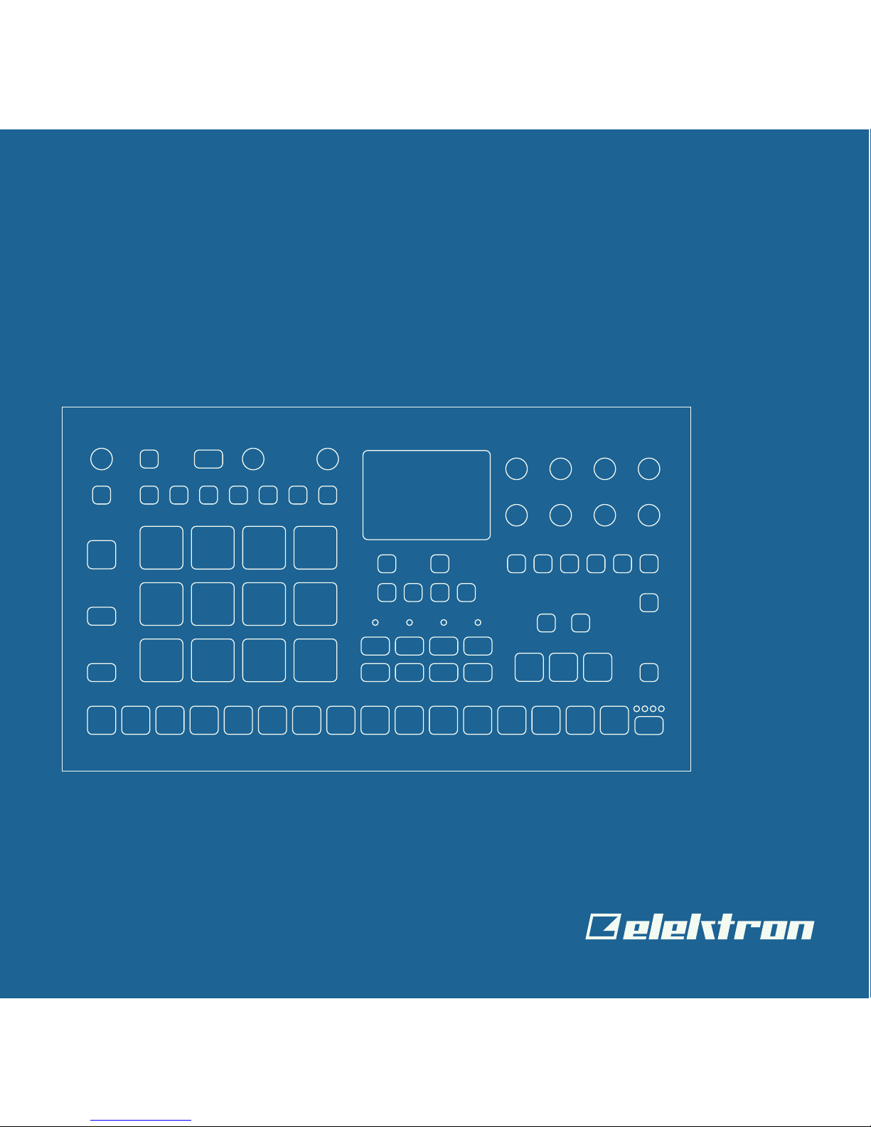
Analog Rytm MKII
A dierent drum
Quick Guide
Page 2

Page 3

3
THANK YOU
Thank you for choosing the Analog Rytm MKII, an eight voice analog/digital hybrid drum
machine featuring the twang of the analog domain, the instant control, and eects of the
digital domain and the wonderful interplay of both. The analog signal path, digital controls,
samples, additive modulation and sampling capability, makes this drum machine a solid
instrument with a voice of its own. The innovative combination of modern technology and
tried and trusted ways of sound generation lets you create any kind of drum: purely analog, sample-based or a combination of the two. For all its layers of complexity and depth, it
remains instantly accessible and - we are sure you agree - fun to play.
This Quick Guide guides you through the basic functions of this product. For more detailed
information, please see the Analog Rytm MKII User Manual that you can download from
www.elektron.se.
We wish you a happy and creative experience. Have fun!
- The Elektron Team
Analog Rytm MKII
Page 4

4
FCC compliance statement
This device complies with part 15 of the FCC rules. Operation is subject to the following two conditions: (1) This device may not cause harmful interference, and (2) this
device must accept any interference received, including interference that may cause
undesired operation.
NOTE: This equipment has been tested and found to comply with the limits for a
Class B digital device, pursuant to Part 15 of the FCC Rules. These limits are designed to provide reasonable protection against harmful interference in a residential
installation. This equipment generates, uses and can radiate radio frequency energy
and, if not installed and used in accordance with the instructions, may cause harmful
interference to radio communications. However, there is no guarantee that interference will not occur in a particular installation. If this equipment does cause harmful
interference to radio or television reception, which can be determined by turning the
equipment o and on, the user is encouraged to try to correct the interference by
one or more of the following measures:
• Reorient or relocate the receiving antenna.
• Increase the separation between the equipment and receiver.
• Connect the equipment into an outlet on a circuit dierent from that to which the
receiver is connected.
• Consult the dealer or an experienced radio/TV technician for help.
Canada
This Class B digital apparatus complies with Canadian ICES-003.
Cet appareil numérique de la classe B est conforme à la norme NMB-003.
Page 5
5
Legal disclaimer
The information in this document is subject to change without notice and should not
be construed as a commitment by Elektron. Elektron assumes no responsibility for
any errors that may appear in this document. Elektron may also make improvements
and/or changes in the products and programs described in this document at any
time without notice. In no event shall Elektron be liable for any special, indirect, or
consequential damages or any damages whatsoever resulting from loss of use, data,
or profits, whether in an action of contract, negligence, or other action, arising out of
or in connection with the use or performance of this information.
European Union regulation compliance statement
This product has been tested to comply with the Low Voltage Directive 2014/35/EU
and the Electromagnetic Compatibility Directive 2014/30/EU. The product meets the
requirements of RoHS 2 Directive 2011/65/EU.
Your product must be disposed of properly according to local laws and
regulations.
Page 6

6
IMPORTANT SAFETY INSTRUCTIONS
1. Do not use this unit near water.
2. Never use aggressive cleaners on the casing or on the screen. Remove dust, dirt
and fingerprints with a soft, dry and non-abrasive cloth. More persistent dirt can be
removed with a slightly damp cloth using only water. Disconnect all cables while doing
this. Only reconnect them when the product is safely dry.
3. To avoid scratches or damage, never use sharp objects near the casing or the screen.
Avoid applying any pressure to the screen itself.
4. Install in accordance with the manufacturer’s instructions. Make sure you place the
unit on a stable surface before use. If you mount the unit in a rack, be sure to tighten all
four screws in the rack mount holes.
5. Connect the unit to an easily accessible electrical outlet close to the unit.
6. When transporting the unit, use accessories recommended by the manufacturer or the
original box and padding.
7. Do not install near any heat sources such as radiators, heat registers, stoves, or any
other equipment (including amplifiers) producing heat.
8. Do not put a protective cover on the unit while the unit is powered on.
9. This product, by itself or in combination with amplifiers, headphones or speakers, is
capable of producing sound levels that may cause permanent hearing loss. Do not
operate at a high volume level or at a level that is uncomfortable.
10. Protect the power cord from being walked on or pinched particularly at plugs, convenience receptacles, and the point where they exit from the unit.
11. Use attachments/accessories specified by the manufacturer.
12. Unplug this unit during lightning storms or when it is not used for long periods of time.
13. Refer all servicing to qualified service technicians. Servicing is required when the unit
has been damaged in any way, liquid has been spilled or objects have fallen into the
unit, the unit has been exposed to rain or moisture, does not operate normally, or has
been dropped.
Page 7

7
WARNING!
TO REDUCE THE RISK OF FIRE, ELECTRICAL SHOCK OR PRODUCT DAMAGE
• Do not expose the unit to rain, moisture, dripping or splashing and also avoid placing
objects filled with liquid, such as vases, on the unit.
• Do not expose the unit to direct sunlight, nor use it in ambient temperatures exceeding
30°C as this can lead to malfunction.
• Do not open the casing. There are no user repairable or adjustable parts inside. Leave
service and repairs to trained service technicians only.
• Do not exceed the limitations specified in the Electrical specifications.
SOUND PEAKS
• A brief 3 kHz signal will be sent to all outs of the Analog Rytm MKII when the Test
mode on the Early Startup menu is activated. Remember to turn down the volume on all
speakers and headphones before activating Test mode.
• During calibration there will be loud and unpleasant sounds on the individual outs.
Disconnect these during calibration.
SAFETY INSTRUCTIONS FOR THE POWER ADAPTER ELEKTRON PSU-3b
• The adapter is not safety grounded and may only be used indoors.
• To ensure good ventilation for the adapter, do not place it in tight spaces. To prevent
risk of electric shock and fire because of overheating, ensure that curtains and other
objects do not prevent adapter ventilation.
• Do not expose the power adapter to direct sunlight, nor use it in ambient temperatures
exceeding 40°C.
• Connect the adapter to an easily accessible electrical outlet close to the unit.
• The adapter is in standby mode when the power cord is connected. The primary circuit
is always active as long as the cord is connected to the power outlet. Pull out the power
cord to completely disconnect the adapter.
• In the EU, only use CE approved power cords.
Page 8

8
TABLE OF CONTENTS
. INTRODUCTION ..................................................................................................................... 10
. CONVENTIONS IN THIS MANUAL ..............................................10
. PANEL LAYOUT AND CONNECTIONS .............................................................................. 11
. FRONT PANEL CONTROLS ...................................................11
. REAR PANEL CONNECTIONS ................................................15
3. OVERVIEW OF THE ANALOG RYTM MKII STRUCTURE ............................................. 16
3.1 +DRIVE .......................................................................16
3.2 DATA STRUCTURE ...........................................................16
3.3 ABOUT THE TRACK TYPES ...................................................18
. USER INTERFACE AND CONTROLS ................................................................................ 19
4.1 SCREEN NAVIGATION ........................................................ 20
4.2 PARAMETER EDITING .......................................................20
4.3 PARAMETER VALUE JUMP ..................................................20
4.4 [FUNC] KEY PRESS COMBINATIONS ........................................20
4.5 QUICK SCROLLING. . . . . . . . . . . . . . . . . . . . . . . . . . . . . . . . . . . . . . . . . . . . . . . . . . . . . . . . . . 20
4.6 COPY, CLEAR AND PASTE ...................................................20
4.7 THE NAMING MENU ..........................................................21
4.8 PADS .......................................................................22
4.9 MACHINES .................................................................. 22
4.10 OVERBRIDGE .............................................................. 24
5. GETTING STARTED ..............................................................................................................24
5.1 SETTING UP AND STARTING ................................................. 24
5.2 PLAYING THE FACTORY PRESETS ........................................... 25
5.3 USING PERFORMANCE MODE ...............................................25
5.4 USING SCENE MODE ........................................................ 26
5.5 USING CHROMATIC MODE ..................................................26
Page 9

9
5.6 USING MUTE MODE .........................................................26
6. THE SEQUENCER ................................................................................................................. 27
6.1 SELECTING A PATTERN ...................................................... 27
6.2 PATTERN CONTROL ........................................................ 27
6.3 TRIG TYPES ................................................................. 28
6.4 PATTERN RECORDING MODES .............................................. 28
6.5 USING GRID RECORDING MODE .............................................28
6.6 USING LIVE RECORDING MODE .............................................28
6.7 PARAMETER LOCKS ........................................................29
6.8 PATTERN MODES ...........................................................30
7. SAMPLING .............................................................................................................................. 30
7.1 SAMPLING FROM EXTERNAL SOURCES ......................................30
7.2 ASSIGNING A SAMPLE TO A TRACK FROM THE +DRIVE ......................32
. TECHNICAL INFORMATION ...............................................................................................33
. CREDITS AND CONTACT INFORMATION ......................................................................34
Page 10

10
. INTRODUCTION
. CONVENTIONS IN THIS MANUAL
In this manual, we use the following conventions to describe the Analog Rytm MKII user
interface:
• KEY NAMES
Written with uppercase, bold style and within brackets. For example, the key labeled
“FUNC” is called [FUNC].
• KNOBS
Written with uppercase, bold, italic letters. For example, the knob “Track Level” is called
TRACK LEVEL.
• MENU NAMES
Written with uppercase letters. For example, the PROJECT menu.
• PARAMETER NAMES, MENU OPTIONS
Written with uppercase bold letters for parameter names and certain menu options
where you can make settings or perform actions. For example, CLOCK SEND.
• PARAMETER SETTING ALTERNATIVES
Written with uppercase letters. For example, OFF.
• SCREEN MESSAGES
Written with uppercase letters with quotation marks. For example, “BANK A: CHOOSE
PTN.”
• LED INDICATORS
Written with uppercase letters with angle brackets. For example, the Pattern page
LEDs are called: <PATTERN PAGE>.
Page 11
11
. PANEL LAYOUT AND CONNECTIONS
. FRONT PANEL CONTROLS
Direct
Kit Sound Track Pattern Song Setup Tap TempoSave Project
Save Kit
MIDI Config
New Chain Edit Song
Sequential Direct Start Direct Jump Temp Jump
Metronome Trig Mute
Scale
Accent Swing Slide Copy Clear Paste Cue Fill
Mute
Sound Browser
Assign Samples Settings
Quantize
BD SD RS CP BT LT MT HT CH OH CY CB
Main Out Ext In Audio In MIDI In MIDI Out MIDI Thru Control InBD LT CH/OHRS/CP USB DC In Power
Delay Reverb Dist Comp LFO
Sync BSync ASD MT/HT CY/CBBT
Main Volume
A
E F G H
B C D
Quick Perf Amount Track Level
1 BD 2 SD 3 RS 4 CP
5
BT
6
LT
7
MT
8
HT
9 CH 10 OH 11 CY 12 CB
Save
Reload
Retrig +
Retrig -µTime - µTime +
2 3 4 5 6 7 8 9 10 11 12 13 14 15 16
A
B
C
D
E
F G H
YES
1 2 10
26
14
28
3 4 5 6 87 9 131211
15
18
19
20
16
17
2425 2223 21
27
29
30
31
32 33 34 35 36
1. MAIN VOLUME sets the volume for the main outputs and the headphones output.
2. [SAMPLING] opens the SAMPLING menu. The secondary function starts Direct
Sampling.
3. [QPER] key. Used to select which performance macro that should be controlled by the
QUICK PERF AMOUNT knob. The secondary function mutes the performance macros.
Page 12

12
4. QUICK PERF AMOUNT sets the amount of the chosen performance macro.
5. [FIX] toggles the FIXED VELOCITY mode for the pads that set them to trigger with a
fixed velocity. The secondary function opens the FIXED VELOCITY menu.
6. TRACK LEVEL sets the overall volume level of the active track. Also used for scrolling
in menus and setting various parameter values. The secondary function opens the
SOUND BROWSER.
7. [TEMPO] opens the TEMPO menu. Use [FUNC] + [TEMPO] to tap the tempo.
8. [NO] key. Used for exiting an active menu, backing one step and negating. If pressed in
combination with keys 32–36 it instantly reloads the kit, Sound, track, pattern or song.
9. [YES] key. Used for entering sub-menus, selecting and confirming. If pressed in combination with keys 32–36 it instantly saves the kit, Sound, track, pattern or song.
10. Screen.
11. The [ARROW] keys. Used for navigation and for setting some parameter values. In
menus, they are called [UP], [DOWN], [LEFT] and [RIGHT].
12. [TRIG] key controls the TRIG settings for the active track. The secondary function
opens the QUANTIZE menu.
13. DATA ENTRY knobs A–H. Used for setting parameter values. Press knob when turning
to change values in larger increments.
14. [PARAMETER] keys access the PARAMETER pages of the active track. The five
parameter page keys are, from left to right:
SRC key accesses the SYNTH parameters of the track Sound. These control the drum
synthesis. When the FX track is active, the DELAY parameter page is accessed. The
secondary function opens the MACHINE selection menu.
SMPL key takes you to the SAMPLE page. Various aspects of the sample playback
are set on this page. When the FX track is active, the REVERB parameter page is
accessed. The secondary function opens the SAMPLE selection menu.
FLTR key accesses the FILTER page. The analog multimode filter parameters are set
here. When the FX track is active, the DISTORTION parameter page is accessed. The
secondary function opens the SOUND SETTINGS menu.
Page 13

13
AMP key takes you to the AMP page, where the shape of the amplitude envelope is
set. When the FX track is active, the COMPRESSOR parameter page is accessed.
LFO key accesses the LFO parameters for the active track.
15. [FX] selects the FX track. Secondary function opens the MIDI CONFIG menu.
16. [SONG MODE] activates/deactivates SONG mode. The secondary function is
SONG edit.
17. [CHAIN MODE] activates/deactivates CHAIN mode. The secondary function
initiates a new CHAIN.
18. [FILL] Activates FILL mode (when GRID RECORDING mode is not active). The secondary function cues the FILL mode.
19. <PATTERN PAGE> LEDs indicate how many pattern pages the active pattern consists
of and which pattern page is currently active. The LED flashes on the pattern page that
is currently playing.
20. [PAGE] selects the active pattern page, if the pattern is made of more than 16 steps.
The secondary function opens the SCALE menu.
21. [STOP] stops playback. The secondary function is a paste operation.
22. [PLAY] starts the sequencer playback. The secondary function is a clear operation.
23. [RECORD] key. Activates/deactivates GRID RECORDING mode. Keep [RECORD]
pressed, then press [PLAY], to activate LIVE RECORDING mode. Activate/deactivate
QUANTIZATION of LIVE RECORDING by keeping [RECORD] pressed, then tapping
[PLAY] twice. The secondary function is a copy operation.
24. [BANK A–H] selects between banks A–H.
25. <PATTERN MODE> LEDs indicate the currently selected PATTERN mode.
26. [PADS] have many possible functions depending on which mode is active and what
each pad is set to do. The primary function is to play the track Sounds. Each drum
track has a dedicated pad.
Page 14

14
27. [TRIG] keys are used for entering or removing sequencer trigs, in combination with the
[PADS], and parameter locks, in combination with the DATA ENTRY knobs. They are
also used to select a pattern, when one of the [BANK] keys is pressed.
28. [RTRG] key will if pressed in combination with one of the [PADS], continuously retrig
the Sound. The secondary function opens the CLICK TRACK menu.
29. [TRK] key. Press [TRK] + one of the [PADS] to select a drum track for editing or
CHROMATIC play. The secondary function saves the current kit.
30. [FUNC] key. Press and hold for accessing secondary functions for some of the other
keys. The secondary functions are written in blue text on the panel.
31. [GLOBAL SETTINGS] opens the GLOBAL SETTINGS menu. The secondary function opens the SAVE PROJECT menu. A long press opens the LOAD PROJECT menu.
32. [PLAY MODE] activates the PLAY mode, in which the pads are used to play the current
sound loaded to every pad. The secondary function opens the KIT menu.
33. [MUTE] activates the MUTE mode. The secondary function opens the SOUND menu.
34. [CHRO] activates the CHROMATIC mode, in which the pads are used to play the
current track Sound chromatically across four octaves. The secondary function opens
the TRACK menu.
35. [SCNE] activates the SCENE mode, in which a one-push instant change of an array of
parameter settings is possible. The secondary function opens the PATTERN menu.
36. [PERF] activates PERFORMANCE mode. The secondary function opens the SONG
menu.
Page 15

15
. REAR PANEL CONNECTIONS
1 32 4 5 6 7 8
9
10 11 12
1. POWER. Turns the unit on and o.
2. DC IN. Use the included Elektron PSU-3b power adapter, connected to a power outlet.
3. USB. Use an A to B USB 2.0 connector cable to a computer host.
4. EXP/CV IN. Input for expression pedal or CV. Use standard 1/4” mono phone plug for
CV signals.
5. MIDI THRU/SYNC B. Forwards data from MIDI IN. Can be configured to send DIN sync
to legacy instruments. Use a standard MIDI cable to connect another MIDI device.
6. MIDI OUT/SYNC A. MIDI data output. Can be configured to send DIN sync to legacy
instruments. Use a standard MIDI cable to connect to MIDI In of an external device.
7. MIDI IN. MIDI data input. Use a standard MIDI cable to connect to MIDI Out of an
external device.
8. AUDIO IN L/R. Inputs for sampling or sound card use. Use 1/4” mono phone plugs.
9. TRACK OUT. Individual drum voice outputs. Use either 1/4” mono phone plugs or 1/4”
Tip/Ring/Sleeve phone plugs.
10. EXT IN L/R. Use 1/4” mono phone plugs to input sound from an external audio source.
11. MAIN OUT L/R. Use either 1/4” mono phone plugs or 1/4” Tip/Ring/Sleeve phone plugs.
12. HEADPHONES OUT. Use standard headphones with 1/4” stereo phone plug.
Page 16

16
3. OVERVIEW OF THE ANALOG RYTM MKII STRUCTURE
The image below outlines the data structure of the Analog Rytm MKII.
MASTER/SEND FX 12 DRUM SOUNDS
12 SONGS 128 PATTERNS 128 KITS 128 SOUNDS 127 SAMPLES
4 GLOBALS
PROJECT +DRIVE
128 PROJECTS
SOUND LIBRARY
SAMPLEBANK
3.1 +DRIVE
The +Drive is a non-volatile storage. It keeps up to 128 projects (thousands of patterns,
kits and songs) stored internally. The +Drive also contains the +Drive Sound library, capable of storing 4096 drum Sounds, and the Sample bank. All projects have access to these
Sounds and samples.
3.2 DATA STRUCTURE
3.2.1 PROJECT
A project contains 128 patterns, 128 kits, 16 songs, 4 global slots, 127 sample slots and
a project Sound pool consisting of up to 128 Sounds. General settings and states are
stored in the project. When a project is loaded it becomes the active working state.
From here it is possible to edit the patterns, kits, songs, and globals of the project.
Projects are saved, loaded and managed in the GLOBAL SETTINGS menu.
Page 17

17
3.2.2 KITS
A kit is a collection of twelve drum track Sounds and the FX track parameter settings.
When you edit a track, changes made to the parameter settings is stored in the active
kit. Each project of the Analog Rytm MKII contains 128 individual kits. A pattern always
links to one of the kits.
3.2.3 SOUNDS
A Sound consists of the parameter settings found in the PARAMETER pages called
SRC, SMPL, FLTR, AMP, and LFO. Sounds are stored in the Sound pool of the active
project or the +Drive Sound library. The Sound pool has 128 Sound slots, and the
+Drive Sound library holds up to 4096 sounds.
3.2.4 SAMPLES
127 user sample slots are available for each project. There are many preset samples to
choose from in the +Drive Sample bank.
3.2.5 PATTERNS
16 patterns are available for each of the 8 banks, which means that 128 patterns are
available for each project. A pattern contains sequencer data like drum trigs, trig mutes
and parameter locks for the drum tracks and the FX track, as well as default settings
on the TRIG page and length, swing, and time signature settings.
3.2.6 SONGS
16 songs are available for each project. You use songs to sequence the playback of
patterns. Songs are built of patterns and chains.
3.2.7 GLOBALS
The GLOBAL settings contain general settings for the sequencer, MIDI, and global
track routing. Four global slots are available for each project, each with its own settings.
3.2.8 GLOBAL
The GLOBAL menu is where you save, load and manage projects, handle SysEx data
and perform OS upgrades. It also contains general settings for the synth and sequencer as well as MIDI and CV configurations. Four global slots are available for every
project, each with its separate settings.
Page 18

18
3.3 ABOUT THE TRACK TYPES
3.3.1 THE DRUM TRACKS
There are 12 drum tracks. Each drum track uses a specific drum voice controlled by
one of the MACHINES available for the voice. All drum tracks can layer analog percussion sounds and sampled sounds, to distort and filter them, and apply a dedicated LFO
each. Press and hold [TRK] key and then press one of the [PADS] to select the track
you want to edit.
3.3.2 THE FX TRACK
The FX track controls the Analog Rytm MKII send eects DELAY and REVERB, as well
as the DISTORTION and COMPRESSOR master eects. One LFO is also available for
this track. To select the FX track for editing, press the [FX] key.
3.3.3 EDITING THE TRACKS
The five [PARAMETER] keys open parameter pages that you use to edit the tracks.
The SRC page of a drum track contains dierent parameters depending on the MACHINE chosen for the analog percussion sound generator. The other pages are identical for all drum tracks; the SMPL page for the sample playback engine, the FLTR page
for the multimode filter and its filter envelope, the AMP page for the amplitude envelope
and eect sends, and the LFO page for the low-frequency oscillator. The corresponding five parameter pages for the FX track controls the four eects and the FX LFO. Use
the DATA ENTRY knobs A-H to edit the parameters. Press and turn a knob to adjust its
parameter in larger increments.
Page 19

19
. USER INTERFACE AND CONTROLS
The screen is the center of Analog Rytm MKII editing.
2 31
4567
1. The currently active kit. The you can see the full name of the parameter you adjust here
when you turn a DATA ENTRY knob.
2. The current tempo displayed with one decimal.
3. The playback/recording status of the sequencer shown by the standard “record”,
“play”, “pause” and “stop” symbols; , , , and .
4. Up to eight track parameters. They show what the DATA ENTRY knobs control and also
indicate the current parameter values. Press and turn a knob to adjust its parameters in
larger increments.
5. The currently active pattern. To the left of this you can see the active song row. A “_ _:”
indicates that the scratch pad row is active
6. Bar that indicates the track level of the active track.
7. Track name.
Page 20

20
4.1 SCREEN NAVIGATION
Use the [ARROW] keys [UP], [DOWN], [LEFT] or [RIGHT] to navigate menus or
sub-menus. The TRACK LEVEL knob can also be used to scroll through menus and lists.
[YES] is used to arm, select, enter sub-menus and tick/untick boxes.
[NO] is used to negate, deselect or go back one or more steps.
4.2 PARAMETER EDITING
The six [PARAMETER] keys open parameter pages where you can edit the tracks. Use
the DATA ENTRY knobs to change the values of the track parameters. The positions of
the parameters on the screen correspond to the physical locations of the knobs on the
front panel.
4.3 PARAMETER VALUE JUMP
If you press [FUNC] when you edit certain parameters, then the parameter values jump to
appropriate positions. For example the oscillator tuning, which will jump in octaves.
4.4 [FUNC] KEY PRESS COMBINATIONS
The standard way to use the [FUNC] key in combination with other keys, is to press and
hold [FUNC] and then make a short press on the second key in the combination.
4.5 QUICK SCROLLING
Scroll through menus using the TRACK LEVEL knob. Quick scrolling is possible on many
menus. Press [FUNC] + the [UP] or [DOWN] keys to move the cursor one menu page.
4.6 COPY, CLEAR AND PASTE
Copy, clear and paste commands are available in a lot of contexts. Press [FUNC] + [RECORD] to copy. Press [FUNC] + [STOP] to paste. Press [FUNC] + [PLAY] to clear. Paste
and clear operations are undone by repeating the key press combination. Please see the
Analog Rytm MKII User Manual for more information.
Page 21

21
4.7 THE NAMING MENU
The naming procedure is identical for all the various naming menus.
The [LEFT] and [RIGHT] arrow keys are used to navigate between the letters. Turn the
TRACK LEVEL knob or press the [UP] or [DOWN] arrow keys to select the letter. [FUNC]
+ [NO] will erase letters.
POP-UP MENU NAMING
While in a NAMING menu it is possible to open a pop-up menu displaying all available letters, symbols, and digits. Entering characters in the pop-up menu is often a considerably
faster naming method. When a NAMING menu is open, press the [FUNC] key to access
the pop-up menu.
While keeping [FUNC] pressed use the [ARROW] keys to navigate to the character you
want to insert. Once there, release [FUNC] to insert the character.
Page 22

22
4.8 PADS
The 12 drum pads on the front panel respond to both velocity and pressure. Tapping a pad
triggers its track sound. BD triggers the bass drum, SD the snare drum and so on. The
illustration outlines and briefly describes the analog percussion sound generators.
MULTI-OSCILATOR SYNTHESIS FOR
HIHAT SOUND GENERATION.
SINGLE-OSCILLATOR SYNTHESIS
CUSTOMIZED FOR BASS TOM SOUND.
DUAL-OSCILLATOR SYNTHESIS
CAPABLE OF A WIDE RANGE OF
SOUNDS.
MULTI-OSCILATOR SYNTHESIS SUITED
FOR VARIOUS CYMBAL AND COWBELL
SOUNDS.
SINGLE-OSCILLATOR SYNTHESIS FOR
LOW- MID- AND HIGH TOM SOUNDS.
DUAL-OSCILLATOR SYNTHESIS WITH
ADDITIONAL RIMSHOT SOUND SHAPING CAPABILITIES.
CH 9 OH 10 CY 11 CB 12
BT
5
BD
1 SD 2 RS 3 CP 4
LT
6 MT 7 HT 8
Use the [PADS] to play the track Sounds of the active kit. Eight individual track Sounds
can be voiced simultaneously with the eight physical voices of the Analog Rytm MKII.
The BD, SD, BT, and LT are independent tracks with their separate voices. The track pairs
RS-CP, MT-HT, CH-OH, and CY-CB, share one voice for each pair and are shown with a
coupling on the front panel of the Analog Rytm MKII. You can also use the [TRIG 1–12]
keys to play the drum tracks when sequencer recording is not active.
The color of the <PADS> shows pad activity. A pad flashes white briefly when engaged,
whether it is played manually or by the Analog Rytm MKII sequencer. A red color pad
shows the active drum track.
4.9 MACHINES
A MACHINE makes use of the physical percussion sound generator of the voice circuit in
a certain way, to make a characteristic drum model.
Page 23

23
For example, the BD track uses the sound generator of the first voice circuit. Its default
BDHD MACHINE includes one tunable analog oscillator, a choice of three dierent waveforms and a custom envelope to shape the sound. These MACHINE-specific synthesis
parameters are found on the SRC parameter page. If you select another MACHINE, it
engages the sound generator dierently - employing more than one oscillator, for example
- enabling the BD track to perform frequency modulation and many other sound generat-
ing techniques.
Press [FUNC] + [SRC] and then use the [ARROW] keys [UP], [DOWN] to select a
MACHINE for the active drum track. Press [YES] to confirm your selection.
All MACHINES cannot be accessed from all tracks since the tracks control dierent physi-
cal sound generators. The illustration above shows the tracks that can make use of
a specific type of percussion sound generator within the boundaries of the same grayshaded box.
These are the twelve tracks and their default MACHINES:
TRACK/PAD MACHINES
1. BD (Bass Drum) 1. HARD, CLASSIC, FM, PLASTIC, SILKY, SHARP
2. SD (Snare Drum) 2. HARD, CLASSIC, FM, NATURAL
3. RS (Rim Shot) 3. HARD, CLASSIC
4. CP (Hand Clap) 4. CLASSIC
5. BT (Bass Tom) 5. CLASSIC
6. LT (Low Tom) 6. CLASSIC
7. MT (Mid Tom) 7. CLASSIC
8. HT (Hi Tom) 8. CLASSIC
9. CH (Closed Hihat) 9. BASIC, CLASSIC, METALLIC
10. OH (Open Hihat) 10. CLASSIC, METALLIC
11. CY (Cymbal) 11. CLASSIC, METALLIC, RIDE
12. CB (Cow Bell) 12. CLASSIC, METALLIC
GENERAL MACHINES: NOISE, IMPULSE
Page 24

24
4.10 OVERBRIDGE
USB
Direct
Kit Sound Track Pattern Song Setup Tap TempoSave Project
Save Kit
MIDI Config
New Chain Edit Song
Sequential Direct Start Direct Jump Temp Jump
Metronome Trig Mute
Scale
Accent Swing Slide Copy Clear Paste Cue Fill
Mute
Sound Browser
Assign Samples S ettings
Quantize
BD SD RS CP BT LT MT HT CH OH CY CB
Main Out Ext In Audio In MIDI In MIDI Out MIDI Thru Control InBD LT CH/OHRS/CP USB DC In Power
Delay Reverb Dist Comp LFO
Sync BSync ASD MT/HT CY/CBBT
Main Volume
A
E F G H
B C D
Quick Perf Amount Track Level
1BD2SD3RS4
CP
5BT6LT7MT8
HT
9CH10OH11CY12
CB
Save
Reload
Retrig +
Retrig -µTime - µTime +
2 3 4 5 6 7 8 9 10 11 12 13 14 15 16
A
B
C
D
E
F G H
YES
The Overbridge software suite enables a tight integration between the Analog Rytm MKII
and a computer DAW.
When using Overbridge, the user interface for the Analog Rytm MKII will present itself as
a clearly laid out plug-in window in your DAW. Access, edit, and automate parameters for
sound shaping on screen. Always find your device preset parameters in the same state as
you left them when you return to your DAW project, with the total recall functionality.
Read more about Overbridge use and availability on the Elektron website: https://www.
elektron.se/overbridge/
5. GETTING STARTED
5.1 SETTING UP AND STARTING
Make sure you place the Analog Rytm MKII on a stable support, such as a sturdy table,
with sucient space for the cables. Make sure to switch o all devices before you connect
the Analog Rytm MKII to other devices.
1. Plug the supplied DC adapter to a power outlet and connect the small plug to the
DC IN connector of the Analog Rytm MKII.
Page 25

25
2. Connect the MAIN OUT L/R from the Analog Rytm MKII to your mixer or amplifier.
3. If you want to use MIDI, connect MIDI OUT from the Analog Rytm MKII to the MIDI
IN of the device you wish to send data to. Connect the MIDI IN of the Analog Rytm
MKII to the MIDI OUT of the device you wish to receive data from. The MIDI THRU
port “echoes” the data arriving at the MIDI IN port, and is used for chaining multiple
MIDI units together.
4. Switch on all units.
5.2 PLAYING THE FACTORY PRESETS
You find several preset patterns, kits, and Sounds in the Analog Rytm MKII. Follow the
instructions below to get started exploring your new instrument.
1. Switch on the Analog Rytm MKII.
2. Press [PLAY] to listen to pattern A01.
3. Press [BANK A] + [TRIG 2] to select pattern A02, which is the second demo pattern. Pattern A02 starts to play when pattern A01 reaches it end. Press [BANK A] +
[TRIG 3] to select pattern A03 and so on.
4. Press [MUTE] + the [PAD] of the drum track you want to mute. Unmute by repeating
the procedure.
5. Press [STOP] to stop playback.
5.3 USING PERFORMANCE MODE
The PERFORMANCE mode enables each one of the twelve pads to control several PARAMETER page parameters at once. Change many dimensions of one or more drum track
Sounds at the touch of a single pad. A set of such parameter locks is called a performance
macro, shown with dim green <PADS>. Try out the preset macros:
1. Make sure a pattern is playing.
2. Press the [PERF] key to enter PERFORMANCE mode.
3. Press the dim green [PADS]. Apply dierent pressures and hear how the sound of
the pattern changes.
Page 26

26
5.4 USING SCENE MODE
The SCENE mode turns the twelve pads into instant sound shifters. Similar to a performance macro, several parameters from any track can be changed by pressing a single
pad. A scene is a fixed set of parameter values, ready to be activated or deactivated,
shown with dim blue <PADS>. A bright blue color pad shows the active scene.
1. Make sure a pattern is playing.
2. Press the [SCNE] key to enter SCENE mode.
3. Tap one of the dim blue color [PADS] to activate a scene. Tap again to deactivate.
5.5 USING CHROMATIC MODE
Any track Sound may be played chromatically using the 12 pads. The chromatic note pitch
is increased linearly for each successive pad pressed: left to right, bottom to top. Twelve
successive pads make one octave. The range spans four octaves, middle, one up and two
down. The middle octave has sky blue color <PADS>, the two below are of violet and dark
blue color, in that order, and the one above is yellow.
1. Select the drum track to play chromatically by pressing [TRK] + one of the [PADS].
2. Press the [CHRO] key to enter CHROMATIC mode.
3. Play the [PADS]. The active track Sound will be pitched dierently for each of the
12 pads comprising the middle octave. Reach higher or lower octaves, one row at a
time, by pressing [ARROW] keys [UP] or [DOWN], respectively
5.6 USING MUTE MODE
You can mute the sequencer of any of the twelve drum tracks in this mode. Unlike the
CHROMATIC mode, it makes no dierence which track is active when this mode is activated. All tracks are accessed simultaneously.
1. Make sure a pattern is playing.
2. Press the [MUTE] key to enter MUTE mode.
Page 27

27
3. Press any of the [PADS] to mute the corresponding track. Press again to unmute.
The color of the <PADS> indicates the mute status. Unlit <PADS> are muted. Green
<PADS> are audible.
4. Press and hold [FUNC] and then any of the [PADS] to preselect a mute, or mute/un-
mute several tracks in one go. Once you release [FUNC], the selected mutes come
into eect. Blue colored <PADS> show the preselected mutes.
6. THE SEQUENCER
The sequencer of the Analog Rytm MKII stores beat information in patterns. A pattern
controls the playback of the drum tracks, the FX track and various pattern-specific aspects of these.
6.1 SELECTING A PATTERN
1. Press [BANK A–H] and then [TRIG 1–16] to select bank and pattern
Patterns containing data are indicated by half-bright red [TRIG] keys. The currently active
pattern is indicated by a full-bright red [TRIG] key.
6.2 PATTERN CONTROL
Press [PLAY] to start the playback of a pattern. Press [STOP] to stop the playback of all
tracks. The sound will be cut o, but eects like Delay will continue to be audible until the
delay repeats have faded out. Quickly press [STOP] twice to stop playback of all tracks
and the fade out of the send eects.
When a pattern is playing and [PLAY] is pressed the playback will pause. Press [PLAY]
again to resume the playback.
If a pattern contains more than 16 sequencer steps, the <PAGE> LEDs will indicate this.
When a pattern is playing, the currently active pattern page is indicated by a blinking,
full-bright, <PAGE> LED
Page 28

28
6.3 TRIG TYPES
A trig is a sequencer event that you can place when you want the sequencer to perform
an action. There are two types of trigs, note trigs, and lock trigs. Note trigs trig notes, while
lock trigs can be used to apply parameter locks without trigging notes. Red [TRIG] keys
indicate note trigs, and yellow [TRIG] keys indicate lock trigs.
6.4 PATTERN RECORDING MODES
The Analog Rytm MKII oers two main modes of inputting trigs when creating a pattern:
GRID RECORDING mode and LIVE RECORDING mode. To create a new pattern first
select an empty pattern slot in one of the banks.
6.5 USING GRID RECORDING MODE
GRID RECORDING is a method of composing where you use the [TRIG] keys to add trigs
in the pattern grid.
1. Press [RECORD] to enter GRID RECORDING mode. The [RECORD] key lights up
red to indicate that GRID RECORDING mode is active.
2. Press [TRK] + one of the [PADS] to select the track to which you want to add trigs.
3. Press the [TRIG] keys 1–16 in the sequence desired to place note trigs on the sequencer. In CHROMATIC mode, you can press [TRIG] + [PADS] to add pitch value
to the note trig.
4. To add a lock trig, press [FUNC] and [TRIG].
5. Press [PLAY] to listen to the sequence.
If the pattern contains more than 16 steps, switch to the pattern page you want to edit by
pressing the [PAGE] key. A fully lit <PAGE> LED indicates the active pattern page..
6.6 USING LIVE RECORDING MODE
LIVE RECORDING mode is the second method of adding trigs to the tracks. In this recording mode, the [PADS] are played in real time to input trigs to the tracks. It is also possible
to enter parameter locks in real time.
Page 29

29
1. Press and hold [RECORD], then press [PLAY] to enter LIVE RECORDING mode.
Quickly pressing [PLAY] twice while keeping the [RECORD] key pressed will acti-
vate/deactivate quantization of LIVE RECORDING. The sequencer will start to play,
and the [RECORD] key will start to flash red.
2. Enter note trigs by playing the [PADS]. Key presses on the [PADS] will be recorded
as note trigs, and the velocity and duration of the key presses will aect the values
of the note trigs. Also, the pitch value of the note trig, if CHROMATIC mode is active,
will be recorded.
3. Turn the DATA ENTRY knobs to record changes to the PARAMETER page settings.
The changes are recorded on the sequencer as parameter locks with lock trigs
added automatically.
4. Press [STOP] to stop both recording and playback of the sequencer.
6.7 PARAMETER LOCKS
Parameter locks is a powerful feature that allows every trig to have its unique parameter
values. All note trigs of a track could, for example, have dierent tune or volume settings.
Parameter locks can be applied to both note trigs and lock trigs.
In GRID RECORDING mode, press and hold the [TRIG] key of a note trig or a lock trig and
then adjust the parameters you want to lock using the DATA ENTRY knobs to apply pa-
rameter locks. The graphics on the screen becomes inverted for the locked parameter and
shows the locked parameter value. The [TRIG] key of the locked trig will begin to flash, to
indicate that the trig now contains a parameter lock.
Press [FUNC] + [TRIG] to enter a lock trig. With a lock trig, you can modulate the sound
without trigging a note.
Remove a single parameter lock by holding [TRIG] + pressing the DATA ENTRY knob of
the locked parameter. If you remove a note trig and then enter it again, all parameter locks
are erased from the trig.
In LIVE RECORDING mode, turn the DATA ENTRY knobs to add parameter locks to the
active track. The parameter will be locked accordingly and lock trigs will automatically be
placed on the sequencer steps.
Page 30

30
6.8 PATTERN MODES
When changing patterns, dierent modes aecting the way the active pattern will be
changed exist. Press [FUNC] + [BANK A–D] to select PATTERN mode. The <PATTERN
MODE> LEDs indicate the selected mode. There are four dierent PATTERN modes:
SEQUENTIAL will change patterns after the currently playing pattern reaches its end.
This mode is the default mode.
DIRECT START will immediately change patterns. The new pattern will start playing
from the beginning.
DIRECT JUMP will immediately change patterns. The new pattern will start playing
from the position where the previous pattern left o.
TEMP JUMP will immediately change patterns. The new pattern will start playing from
the position where the previous pattern left o. It will play the new pattern once and
then revert to the pattern that was playing before the change.
7. SAMPLING
Analog Rytm MKII can also sample audio. It can sample audio both from external sources
via the AUDIO IN inputs, and internally from the Analog Rytm MKII itself.
7.1 SAMPLING FROM AN EXTERNAL SOURCE
1. Connect your audio source to the AUDIO IN L/R inputs of the Analog Rytm MKII.
Page 31

31
2. Press [SAMPLING] to access the SAMPLING menu and then use DATA ENTRY
knob G to set SOURCE to AUD L+R.
3. Keep an eye on the audio input meter and play the audio source and make sure that
the volume of the audio source is as strong as possible, but without clipping. Set
MON to YES to monitor the incoming audio through the Analog Rytm MKII.
4. Again, with an eye on the audio input meter and use DATA ENTRY knob F to set
THRESHOLD just above the indicated background noise of the audio source (when
it is not playing).
5. Press [YES] to arm the sampling and then play the sound source. When the input
audio exceeds the set THRESHOLD level, sampling will start.
6. Press [YES] when you want to stop the sampling.
7. Use the DATA ENTRY knobs A and C to set the parameters TRIM START and TRIM
END to trim the sample to the desired length. You can use the DATA ENTRY knobs
B and D to zoom in and out to make it easier to see where to trim the sample. Press
[FUNC] + [YES] to preview the sample.
8. Press [YES] to save the sample.
9. Name your sample and press [YES] again to confirm the save.
10. Press one of the [PADS] to select the track to where you want to assign the sample.
Page 32

32
7.2 ASSIGNING A SAMPLE TO A TRACK FROM THE +DRIVE
You can also assign samples from the +Drive storage in the Analog Rytm MKII to the tracks.
1. Press [SETTINGS] to access the SETTINGS menu, and then select SAMPLES and
press [YES].
2. Use the [ARROW] and [YES] keys to navigate to the sample you want to assign,
and then press [YES] to select the sample.
3. Press [RIGHT], and then select LOAD TO PROJ and press [YES] to load the sample
to the project.
4. Press [YES] to confirm.
5. Press [SETTINGS] to exit SETTINGS menu.
6. Press [TRK] + [PADS] to select the track to where you want to assign the sample.
7. Press [SMPL] to access the SAMPLE parameter page, and then use DATA ENTRY
knob D to select the sample you want to load.
8. Press [YES] to load the sample to the track.
Page 33

33
. TECHNICAL INFORMATION
ELECTRICAL SPECIFICATIONS
Impedance balanced audio outputs:
Main outputs level: +15 dBu
Output impedance: 440 unbalanced
Individual outputs:
Output level: +15 dBu
Output Impedance: 440
Headphones output:
Headphones out level: +15 dBu
Output impedance: 55
Unbalanced external inputs:
Input level: +15 dBu maximum
Audio input impedance: 9 k
Balanced audio inputs:
Input level: +15 dBu maximum
Audio input impedance: 19 k
Digital S/N ratio: 105 dBFS (20–20,000 Hz)
Unit power consumption: 16 W typical,
22 W maximum.
Recommended power supply: PSU-3b or
similar, 12 V DC, 2 A
HARDWARE
128×64 pixel OLED screen
MIDI In/Out/Thru with DIN Sync out
2 x 1/4” impedance balanced audio out
jacks
1 x 1/4” stereo headphone jack
8 x 1/4” impedance balanced individual
track output jacks
2×1/4” balanced audio in jacks
2×1/4” ext in jacks
2×1/4” CV/Expression inputs
48 kHz, 24-bit D/A, and A/D converters
Flash-EEPROM upgradable OS
Electrically isolated USB 2.0 port
PHYSICAL SPECIFICATIONS
Aluminum enclosure
Dimensions: W385×D225×H82 mm
(15.2×8.85×3.3) including knobs, jacks
and feet
Weight: approximately 2.4 kg (5.3 lbs)
Page 34

34
. CREDITS AND CONTACT INFORMATION
CREDITS
PRODUCT DESIGN AND DEVELOPMENT
Oscar Albinsson
Ali Alper Çakır
Oscar Dragén
Magnus Forsell
Anders Gärder
Andreas Henriksson
Fabian Hundertmark
Christer Lindström
Jimmy Myhrman
Jon Mårtensson
Viktor Nilsson
David Revelj
Mattias Rickardsson
Martin Sigby
Daniel Troberg
ADDITIONAL DESIGN
Ufuk Demir
Thomas Ekelund
DOCUMENTATION
Daniel Sterner
Erik Ångman
CONTACT INFORMATION
ELEKTRON WEBSITE
https://www.elektron.se
OFFICE ADDRESS
Elektron Music Machines MAV AB
Sockerbruket 9
SE-414 51 Gothenburg
Sweden
TELEPHONE
+46 (0)31 743 744 0
Page 35

35
Page 36

8261ENG-A
 Loading...