

Electromotive XDI200 Installation Manual & Users Manual
XDI200
Product Installation Manual
& User’s Guide
V 01
Electromotive, Inc. 703-331-0100
9131 Centreville Road 703-331-0100 fax
Manassas, VA 20110 support@electromotive.com

Table of Contents
1 Terms and Conditions ........................................................ 6
1.1 ELECTROMOTIVE, INC. PRODUCT WARRANTY .......................................... 6
2 Forward................................................................................ 7
2.1 Improvements of the XDI200 over the TECgt ................................................... 8
2.2 Fundamentals of the System ............................................................................ 8
3 Installing the Hardware .................................................... 10
3.1 Pre-Installation Checklist ................................................................................ 10
3.2 Mounting the Main Computer and DFU .......................................................... 10
3.3 Trigger Wheel and Sensor Installation ............................................................ 12
3.3.1 Crankshaft Trigger Installation for 60(-2) Tooth Wheel ............................... 12
3.3.2 Hall Effect or Magnetic Crank Sensors ....................................................... 12
3.3.3 Crank Sensor Installation ............................................................................ 13
3.3.4 Wiring a Magnetic Trigger Sensor ............................................................... 15
3.3.5 Verifying Trigger Wheel Timing ................................................................... 16
3.3.6 Camshaft- & Distributor-Mounted Trigger Setups ....................................... 18
3.3.7 Individual Cylinder trim application – Cam Synchronization ........................ 18
3.3.8 TDC Tooth Setup Software Adjustment Parameters ................................... 20
4 Wiring the System ............................................................ 23
4.1 Introduction ..................................................................................................... 23
4.1.1 Suggestions on Crimp Terminals… ............................................................. 23
4.2 Wiring ECU & Main Power .............................................................................. 24
4.2.1 Power Harness Installation ......................................................................... 24
4.3 Wiring Ignition Coil Primary Sides................................................................... 25
4.3.1 Introduction ................................................................................................. 25
4.3.2 Standard Direct Fire Units, DFU’s ............................................................... 26
4.3.3 Wiring Standard DFU’s Coils ...................................................................... 26
4.3.4 Spark Plug Wiring High Voltage Side .......................................................... 28
4.4 Ignition Firing Order ........................................................................................ 30
4.4.1 Common Engine Sparkplug Wiring ............................................................. 31
4.5 Coil Firing Schemes ........................................................................................ 32
4.5.1 Coil Firing Patterns for EVEN-FIRE Engines .............................................. 32
4.5.2 Coil Firing Patterns for ROTARY Engines ................................................... 33
4.5.3 Coil Firing Patterns for 2-CYCLE Engines .................................................. 33
4.5.4 Coil Firing Patterns for ODD-FIRE Engines ................................................ 34
4.5.5 Examples of Typical Engine Setups ............................................................ 34
4.5.6 Common Firing Orders ................................................................................ 37
4.5.7 How to find the TDC Event Order : .............................................................. 38
4.5.8 TDC Tooth for DFU “2” needed for an Odd-Fire Engine: ............................ 38
4.5.9 Harley-Davidson Applications ..................................................................... 38
4.5.10 Rotary Engines............................................................................................ 38
4.5.11 Dual Plug Engines ....................................................................................... 39
4.6 Spark Plug Wire Selection .............................................................................. 39
4.7 Spark Plug Selection ...................................................................................... 40
4.8 Driver on Coil Logic Driven Coils .................................................................... 42
5 Wiring Sensors & Other Inputs ....................................... 43
5.1 The Manifold Air Pressure (MAP) Sensor ....................................................... 43
________________________________________________________________________
XDI200 Manual Version 0.1 - Page 2 - ©2017 Electromotive, Inc.

5.1.1 MAP Sensor Data ....................................................................................... 44
5.2 Throttle Position Sensor ................................................................................. 45
5.3 TPS Wiring ..................................................................................................... 46
5.4 Coolant Temperature Sensor ......................................................................... 47
5.5 Manifold Air Temperature Sensor ................................................................... 49
5.6 The Exhaust Gas Oxygen Sensor .................................................................. 50
5.6.1 Mounting the EGO Sensor .......................................................................... 50
5.6.2 Wiring the EGO Sensor ............................................................................... 50
5.6.3 EGO Functionality ....................................................................................... 51
5.6.4 About One-Wire EGO Sensors ................................................................... 52
5.7 Wideband O2 Sensor ..................................................................................... 52
5.7.1 Wideband EGO Information and Installation Instructions ............................ 52
5.8 Secondary EGO sensor input ......................................................................... 53
5.8.1 EGO FAQ’s and Troubleshooting Tips: ....................................................... 53
5.9 Knock Sensor ................................................................................................. 53
5.10 Auxillary Temperature Sensor Input ............................................................ 55
5.11 General Purpose Inputs (GPI’s) .................................................................. 55
5.11.1 Available General Purpose Input (GPI) Functons ...................................... 56
5.11.2 Wiring the GPI’s .......................................................................................... 57
6 Wiring Outputs .................................................................. 59
6.1 Idle Air Control Motor ...................................................................................... 59
6.1.1 Wiring a 2-wire IAC: .................................................................................... 60
6.1.2 Wiring a 3-wire IAC: .................................................................................... 60
6.2 Tachometer Output ......................................................................................... 62
6.3 Fuel Pump Relay Output ................................................................................ 62
6.4 General Purpose Output (GPO) functions : .................................................... 63
6.4.1 Outputs ....................................................................................................... 64
6.4.2 Available GPO Functions ............................................................................ 64
6.4.3 Wiring the GPO’s: ....................................................................................... 65
7 Communications Ports on the XDI200 ........................... 67
7.1.1 PC communications, USB port .................................................................... 67
7.1.2 PC communications, RS232 Serial port ...................................................... 67
7.1.3 CAN bus serial port ..................................................................................... 67
8 Tuning Guide..................................................................... 68
8.1 Introduction ..................................................................................................... 68
8.2 Adjusting the Timing Advance ........................................................................ 68
8.3 Getting the Engine to Idle ............................................................................... 69
8.4 Tuning the Idle Air Control Motor .................................................................... 69
8.4.1 Configuring the New Electromotive Idle Speed Control .............................. 69
8.4.2 Idle Speed primer ........................................................................................ 70
8.4.3 Getting the IAC Started ................................................................ ............... 70
8.4.4 Error Sensitivity ........................................................................................... 71
8.4.5 RPM Rate-of-Change Sensitivity ................................................................. 71
8.5 Tuning Tips: .................................................................................................... 72
8.5.1 Other tips: ................................................................................................... 72
8.5.2 Absolute vs. Gage Pressure ....................................................................... 73
8.5.3 Units of Measurement ................................................................................. 73
9 Diagnostics ....................................................................... 75
________________________________________________________________________
XDI200 Manual Version 0.1 - Page 3 - ©2017 Electromotive, Inc.

9.1 Trouble Codes from the LED’s Mounted on the XDI200 ................................. 75
9.2 Trouble Codes from the Check Engine Output ............................................... 76
9.3 Trouble Code Descriptions ................................................................ ............. 77
9.3.1 Using the Trouble Codes ............................................................................ 78
9.3.2 Wiring the Check Engine Light .................................................................... 79
9.4 Tuning the Knock Control ............................................................................... 80
9.5 Using the Ignition Advance Trims ................................................................... 80
10 Data logging with the XDI200 .......................................... 80
10.1 PC-Based Data logging ............................................................................... 80
10.2 On-Board Data logging ............................................................................... 81
11 Rev Limiters ...................................................................... 81
11.1 Valet Mode Rev Limiter ............................................................................... 81
11.2 Secondary Rev Limiter : .............................................................................. 81
11.3 Primary Rev Limiter : ................................................................................... 82
11.4 Zero degree advance .................................................................................. 82
11.5 3-stage coil cut ............................................................................................ 82
11.6 Full coil cut ................................................................................................ .. 82
12 Troubleshooting ............................................................... 82
12.1.1 Air, Fuel, and Spark .................................................................................... 83
12.2 Starting Problems ........................................................................................ 83
12.2.1 Air-Related Starting Problems ..................................................................... 83
12.2.2 Fuel-Related Starting Problems .................................................................. 83
12.2.3 Spark-Related Starting Problems ................................................................ 83
12.3 Idling Problems ........................................................................................... 84
12.3.1 Air-Related Idling Problems ........................................................................ 84
12.3.2 Fuel-Related Idling Problems ...................................................................... 84
12.3.3 Spark-Related Idling Problems ................................................................... 85
12.4 Low-, Medium-, and High-Load Problems ................................................... 85
12.4.1 Air-Related Load Problems ......................................................................... 85
12.4.2 Fuel-Related Load Problems ...................................................................... 85
12.4.3 Spark-Related Load Problems .................................................................... 85
13 Appendix I. ECU Specifications ..................................... 86
13.1 OUTPUTS ................................ ................................ ................................... 86
13.1.1 Coil Outputs ................................................................................................ 86
13.1.2 Idle Air Control (IAC) Motor ......................................................................... 86
13.1.3 General Purpose s (GPO’s) ........................................................................ 86
13.1.4 Fuel Pump Control ...................................................................................... 86
13.1.5 Tachometer Output ..................................................................................... 86
13.1.6 Check Engine Light Output ......................................................................... 86
13.1.7 ECU Diagnostic Check engine Lamp .......................................................... 86
13.2 INPUTS ....................................................................................................... 86
13.2.1 General Purpose Inputs (GPI’s) .................................................................. 86
13.2.2 Engine Sensor Inputs .................................................................................. 86
13.2.3 Angle Based Timing Control ....................................................................... 87
13.2.4 Feedback Charging Control ........................................................................ 87
13.3 Tuning Features .......................................................................................... 87
13.3.1 Ignition Timing Map ................................ ................................ ..................... 87
13.3.2 Rev Limiters ................................................................................................ 87
________________________________________________________________________
XDI200 Manual Version 0.1 - Page 4 - ©2017 Electromotive, Inc.

13.3.3 On-Fly Tuning ............................................................................................. 87
13.3.4 Compensation Features .............................................................................. 87
13.4 Supported Engine Configurations ............................................................... 88
13.4.1 4-Stroke ...................................................................................................... 88
13.4.2 2-Stroke ...................................................................................................... 88
13.4.3 Rotary ......................................................................................................... 88
13.5 Data logging Features ................................................................................. 88
13.5.1 Laptop Data logging .................................................................................... 88
13.6 Physical Dimensions ................................................................................... 88
13.7 Environmental Considerations .................................................................... 88
13.8 PC Requirements ........................................................................................ 88
14 Appendix II. Trigger Wheel Availability ......................... 89
15 Appendix III. Secondary Coil Polarity for Redundant Ignition
Applications ............................................................................. 90
16 Software & Firmware Support ......................................... 91
16.1.1 Software Coding Information ....................................................................... 91
16.1.2 Firmware Coding Information ...................................................................... 91
16.1.3 Software Upgrade Procedure ...................................................................... 91
16.1.4 Firmware Upgrade Procedure ..................................................................... 92
17 Appendix IV. ECU Connector Pin Out List ..................... 93
18 Appendix V. ECU Connector Drawing ........................... 94
19 Appendix VII. Driver on Coil Schematic ........................ 96
20 Glossary of Terms ............................................................ 97
________________________________________________________________________
XDI200 Manual Version 0.1 - Page 5 - ©2017 Electromotive, Inc.

1 Terms and Conditions
1.1 ELECTROMOTIVE, INC. PRODUCT WARRANTY
Products manufactured by Electromotive (XDi Ignitions and TEC ECUs) are built to last. Many of
our products have been in service for multiple decades. Products sold, but not manufactured, by
Electromotive are warranted as described under Other Products and Parts We Sell.
Should your product not be functioning properly during the warranty period, please first check
Tech Support information available at www.electromotive-inc.com under the Support tab. You
may find that the issue is due to something other than unit malfunction.
Our warranty period is 1 year as of January 1, 2017.
New Product Warranty:
With a 1 year limited warranty, Electromotive offers, by far, one of the best warranties in the
business on all new XDi and TEC units, for the original purchaser only, from the original purchase
date. We warrant our products to free of defects in materials and workmanship during the
warranty period. The replacement product will, in turn, be warranted for 1 year from the date of
replacement. Electromotive will pay for standard shipping to return the repaired/replacement unit
to the customer, if a defect covered under warranty is found.
Note: At Electromotive’s discretion, products that show evidence of tampering, abuse, accident
damage, or other unusual wear and tear conditions may not be eligible for warranty coverage.
See details under Warranty Exclusions.
If You Need Warranty Service:
Notify us at support@electromotive-inc.com or 703/ 331-0100 M-F 8:30 to 5:00 EST. Then, send
(1) a note with a summary of the issues you are experiencing, (2) a copy of your sales receipt,
and (3) the XDi or TEC unit. Ship to: Electromotive Repairs, 9131 Centreville Road, Manassas,
VA 20110. You must include the purchase receipt and it must clearly show name of the
seller, date of purchase and purchase amount.
Our policy is to provide a new or factory refurbished replacement unit rather than repair units
under warranty, at our discretion. If the issue is something very minor, we may opt to repair
rather than replace. Replacement products may include remanufactured or refurbished products
or components.
If your product is shown to be in complete working order when we receive it, you may be
charged a small fee for handling and return shipping.
Out-of-Warranty Product Repair
Should your product be out of warranty, we offer factory diagnosis and repair services. There is a
small fee for diagnosis and estimation of repair costs. Check with us for the current diagnosis
fee. You will have options including (1) repair, (2) (if available) purchasing a refurbished unit, or
(3) trading your old unit for a discount off a new unit. We strive to keep our repair times to within
5 business days, plus shipping days.
Other Products And Parts We Sell:
We make every attempt to source products that live up to our quality standards. In the rare
occasion that one of these products/parts fails within 90 days of purchase, return it to us along
with a copy of your sales receipt and we will replace it if, at our discretion, the malfunction is not
due to the same exclusions listed under Warranty Exclusions.
________________________________________________________________________
XDI200 Manual Version 0.1 - Page 6 - ©2017 Electromotive, Inc.

Warranty Exclusions:
Any product, on which the serial number has been defaced, modified or removed or doesn’t
appear in the Electromotive serial number registry.
Damage, deterioration, or malfunction deemed to be from:
Accident, misuse, neglect, fire, water, lightning, or other acts of nature, unauthorized product
modification, tampering, or failure to follow instructions supplied with the product/available for
download from www.electromotive-inc.com
Repair or attempted repair by anyone not authorized by Electromotive.
Any damage due to shipment.
Removal or installation of the product.
Causes external to the product such as electric power fluctuations or failure
Use of supplies or parts not meeting Electromotive specifications.
Any other cause, which does not relate to a product defect.
Limitation of Implied Warranties:
There are no warranties, expressed or implied, which extend beyond the description contained
herein including the implied warranty or merchantability and fitness for a particular purpose.
Exclusion of Damages:
Electromotive’s liability is limited to the cost of repair or replacement of the product.
Electromotive shall not be liable for:
Any costs for removal, installation, tuning or set up of the unit before or after the malfunction.
Damage to other property caused by any defects in the product.
Damages based upon inconvenience, loss of use of the product, loss of time, loss of profits, loss
of business opportunity, loss of goodwill, interference with business relationships, or other
commercial loss, even if advised of their possibility of such damages.
Any other damages, whether incidental, consequential or otherwise
Any claim against the customer by another part.
Certain shipping charges.
2 Forward
The XDI200 Distributorless Ignition system is the latest ignition system in the expanded
line of ultra-high resolution engine management systems from the company that revolutionized
engine management over twenty years ago. The XDI200 can be configured to control the
ignition of virtually any 1, 2, 3, 4, 6, 8 or 12 cylinder engine, as well as 1 or 2-rotor rotary engines,
and dual plug 4 or 6 cylinders. The heart of the XDI systems has always been a high-resolution
ignition, which offers incredibly precise ignition timing even at the highest acceleration rates. The
XDI200 continues this tradition; only what was once done with an analog ignition circuit is now
done with a high-speed microprocessor. Direct Fire Units (DFU’s) with twin-tower coils are
available from Electromotive in 2- and 3-coil versions. Single tower coils are available as well.
These DFU’s are completely weather proof, and feature sealed electrical connectors.
Additionally, the DFU’s are impedance matched for optimum performance with our XDI200.
There are Nine dedicated, user-definable, general-purpose inputs / outputs (GP I/O’s)
included with the XDI200 to make your high-tech engine setup a snap. The GP I/O’s can be used
to control anything from wastegates for turbo setups to simple electric radiator or intercooler fans.
The possibilities are nearly limitless.
________________________________________________________________________
XDI200 Manual Version 0.1 - Page 7 - ©2017 Electromotive, Inc.

One of the GPI’s has a frequency-based input capability, which can process data from
wheel a speed sensor or similar device. The other GPI’s are analog inputs only, and do not
feature frequency-based capabilities. These channels can perform timing trims, and many other
functions.
Besides the GP I/O’s, several functions are built-in to the XDI200 that are quite useful on
most applications. The following outputs are standard on the XDI200:
Tachometer (configurable to drive most modern tachs)
Check Engine Light
Fuel Pump Relay Ground (activated at appropriate times by the XDI200
Idle Speed Motor control (stepper motor style or 2-wire style)
The XDI200 uses the following inputs to perform engine management:
Crank Trigger
Cam Trigger (optional)
Manifold Air Pressure
Coolant Temperature Sensor
Manifold Air Temperature Sensor
Throttle Position Sensor
Knock Sensor (optional)
Exhaust Gas Oxygen Sensor (O2 sensor)
2.1 Improvements of the XDI200 over the TECgt
The XDI200 has the added features of:
1. Water resistant case and connector system
2. 6 high current ignition coil drivers to operate 12 cylinder or dual plug 6 cylinder
engines.
3. 6 separate ignition coil logic outputs to operate up to 12 Driver On Coil (DOC) coils.
4. User selected fixed coil dwell time or standard coil current control.
5. General Purpose Inputs(GPI) separated from General Purpose Outputs(GPO)
6. On board USB port for direct connection to Laptop PCs.
7. Retained RS232 Serial port like older TECs with same functionality
8. New Second Oxygen sensor input
9. New Third temperature sensor input
10. High power Tach signal driver
11. Two range knock sensor sensitivity
12. Added 2 more GPO outputs
13. Dedicated road speed frequency input
14. Future Twin Variable Valve Timing cam input and output control
2.2 Fundamentals of the System
The goal behind Electromotive’s Total Engine Control product line is to provide complete, highresolution control of all functions of the modern engine, and to do so with a user-friendly interface.
Consequently, the XDI200 is designed to easily control a huge number of complex engine
management functions through the hands of a user who is new at the game.
________________________________________________________________________
XDI200 Manual Version 0.1 - Page 8 - ©2017 Electromotive, Inc.

Engine Speed & Position = Crank Sensor…
What separates our engine management systems from those of our competitors is the fact
that our products are all designed around an ultra high-resolution ignition. For this reason, we
use a 60(-2) tooth crank trigger wheel to give the computer an extremely accurate engine position
input. This is also the reason that we do not support any other types of trigger inputs. Take, for
instance, the flying magnet trigger input used by some manufacturers: 8 cylinder engines have 4
magnets mounted to the crank trigger wheel. Our 60(-2) tooth trigger has 15 TIMES MORE
RESOLUTION! From a magnetic sensor aimed at the trigger wheel, the XDI200 receives its
input for engine speed and position.
Engine Load = MAP Sensor…
As nice as the 60(-2) tooth trigger wheel is for determining engine speed and position,
more is necessary to perform ignition and fuel control; namely a load input. While many OEM’s
use Mass Airflow (MAF) sensors to determine the airflow (and thus the load) of an engine,
Electromotive systems are designed around Manifold Air Pressure (MAP) sensors as the loaddetermining device. MAP sensors simply plug into the intake manifold of the engine (after the
throttle), and are inherently easier to install than MAF sensors since they are not sensitive to
vacuum leaks or engine airflow requirements. A 1-Bar MAP sensor is designed for naturally
aspirated engines. A 2-Bar sensor is used for turbo/supercharged engines with up to 15psi
(about 200kPa absolute) manifold boost. A 3-Bar sensor is good for up to 30psi (300kPa), while
a 4-Bar is good for up to 45psi (400kPa). Choose the appropriate sensor for the application, and
you are done.
Ignition Advance Control…
Once the MAP sensor and crank sensor are installed, the XDI200 has inputs for RPM and
load. Under steady-state conditions on a fully warmed-up engine, these are the only necessary
inputs for the XDI200 to control the fuel and ignition curves. Control of the ignition advance curve
is quite simple: there is a table of RPM vs. MAP in which the desired ignition advance angle is
entered for every point. The table can be made in any size from 8x8 to 16x16 data points.
Between each data point, there is a 256 point interpolation occurring. This keeps the advance
curve from “stepping” from point-to-point. Additionally, it means that the engine can be tuned with
only a few input numbers; some other systems on the market rely on the tedious input of
hundreds of numbers to obtain an ignition advance curve that is still not as smooth between data
points as ours.
Compensations…
Having a warmed-up engine running under steady-state conditions is all well and good, but
in the real world, we must deal with cold weather starting, engine accelerations and
decelerations, etc. For these scenarios, engines need fuel and spark compensations. The
coolant temperature sensor (CLT) provides an input for the XDI200 to measure the engine
temperature. Since cold engines need more fuel than hot engines, tables are provided in the
software to allow fuel flow increases as a function of engine temperature. Other parameters
related to the coolant temperature are cold starting (cranking) enrichments and throttle movement
enrichments when cold
Additional Features…
Once all the necessary input sensors are in place, and the software is tuned, the engine
will run quite well. However, to further refine the control of the engine, a few additional features
are included. The idle air control motor (IAC) is used to meter air into the engine at idle. This
________________________________________________________________________
XDI200 Manual Version 0.1 - Page 9 - ©2017 Electromotive, Inc.

helps maintain a smooth idle, regardless of operating conditions. It can also be used to increase
the idle for cold temperatures, or air conditioner activation. A fuel pump output is also included,
which allows the user to turn on the fuel pump relay for a set amount of time when the ignition is
turned on. This primes the fuel system, and powers the fuel pump once the engine is cranked
and running. A tachometer output is included, which will drive most modern tachometers, and a
check engine output is included to keep track of failed engine sensors. A host of other engine
input and output options are included as well, and are outlined in other areas of this manual.
3 Installing the Hardware
3.1 Pre-Installation Checklist
To perform a complete XDI200 installation, the following items are required:
1. XDI200 Computer
2. DFU(s) or Driver on Coil Ignition Coils.
3. Resistor Core Spark Plug Wires (see notes on Spark Plug Wires)
4. XDI200 Wiring Harness w/ Power Harness
5. Windows-based PC-type Computer (see notes on Computer Requirements)
6. Serial Connector Cable (DB9) for PC or USB Cable
7. Crank Position Sensor (Magnetic Sensor)
8. 60 (-2) Tooth Crank Trigger Wheel or 120 (-4) Tooth Cam Trigger Wheel
9. Coolant Temperature Sensor (CLT) (OPTIONAL)
10. Manifold Air Temperature Sensor (MAT) (OPTIONAL)
11. Manifold Air Pressure Sensor (MAP) (OPTIONAL)
12. Throttle Position Sensor (TPS) (OPTIONAL)
13. Exhaust Gas Oxygen Sensor (EGO) (OPTIONAL)
14. Idle Air Control Motor (IAC) (OPTIONAL)
15. Knock Sensor (KNK) (OPTIONAL)
16. Wire Terminal Crimping Tool (available from Electromotive)
17. Shrink Tubing
18. Assorted Wire Crimp Terminals
19. Drill
20. ¼” Bolts for DFU(s) & XDI200 ECU
21. Soldering Gun
3.2 Mounting the Main Computer and DFU
For utmost reliability, install the XDI200 computer where temperatures will not exceed
150oF (65oC). The XDI200 computer should be installed in the passenger compartment of the
vehicle where it will not be exposed to the elements. A good location is in the kick panel of a
vehicle originally equipped with a factory ECU. As a second choice, the XDI200 may be mounted
in an area that is partially exposed to the elements. It must not be mounted above or close to any
exhaust or oil piping. A well vented area is recommended, particularly in engines utilizing most of
the ignition channels and operating at sustained high speeds. It should be noted that the XDI200
might get hot under prolonged high-rpm operation. As long as air is moving around the ECU,
there is no risk of damage to the XDI200; just be careful not to burn yourself on the unit! Secure
the XDI200 ECU with four ¼” socket head cap screws. If the wiring harness goes through the
firewall, a suitable grommet must be used to avoid chafing.
________________________________________________________________________
XDI200 Manual Version 0.1 - Page 10 - ©2017 Electromotive, Inc.
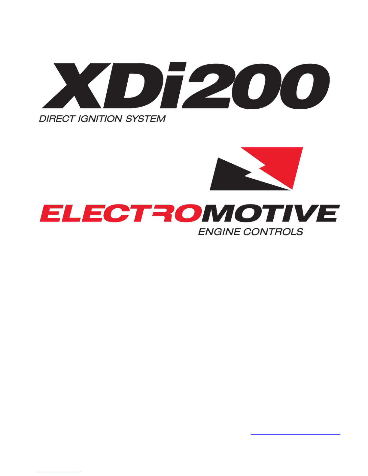
The DFU(s) can be placed nearly anywhere under the hood of the vehicle where the
2-Coil DFU Dimensions 3-Coil DFU Dimensions
temperatures are below 250oF (120oC). Since they are entirely sealed, exposure to the elements
is not an issue. The DFU Ground Wire MUST be installed to vehicle ground.
It is recommended that the ECU and DFU be separated by at least six inches for the
purpose of reducing electrical noise in the ECU.
Figure 1. Electromotive Direct Fire Units
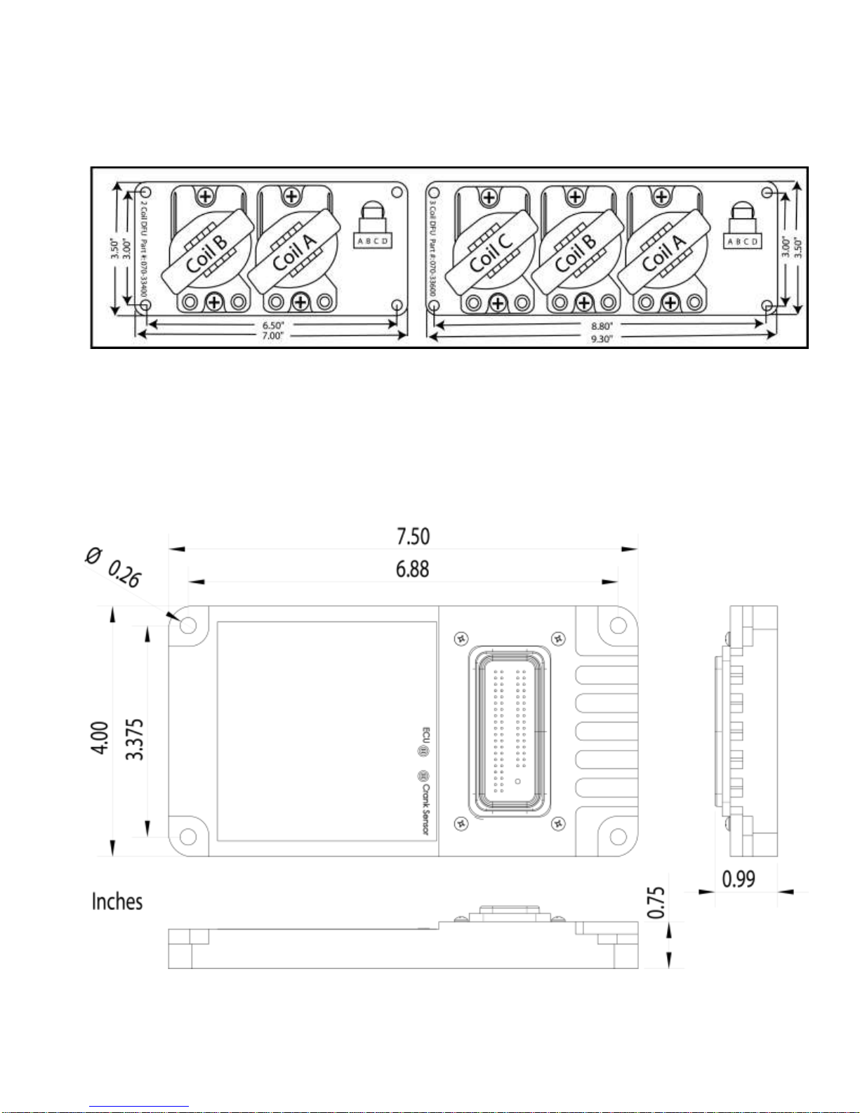
Mounting bolt pattern is 3.375” x 6.88”
________________________________________________________________________
XDI200 Manual Version 0.1 - Page 11 - ©2017 Electromotive, Inc.

Figure 2. XDI200 ECU
3.3 Trigger Wheel and Sensor Installation
The foundation of the XDI200 ultra-high resolution ignition is
the 60(-2) tooth trigger wheel. The trigger wheel is designed to give
uncompromising timing accuracy at the highest engine acceleration
rates. As such, Electromotive does not support other triggering
systems, particularly those of the “flying magnet” variety. These
systems can lead to vastly inaccurate spark timing, and can
contribute to engine damage. For most applications, the 60(-2) tooth
trigger wheel is mounted on the crankshaft damper or pulley. Some
applications may warrant the use of a camshaft- or distributor-mounted trigger wheel. With this
setup, a 120(-4) tooth trigger wheel is necessary, since the camshaft turns at half the speed of
the crank.
3.3.1 Crankshaft Trigger Installation for 60(-2) Tooth Wheel
For a crankshaft-mounted trigger wheel setup, an appropriate place must be found to
mount the wheel and trigger. Typically, the easiest place to mount a trigger wheel is on the
harmonic damper or pulley. If it is mounted on a damper, it should be mounted on the inner hub
rather than the outer dampening ring. The damper/pulley should be keyed to the crankshaft so
that it cannot spin on the crankshaft, as this would cause an ignition timing error. When using a
damper that has bolt-on pulleys, the trigger wheel can usually be mounted between the pulleys
and the damper. However, the accessory pulleys will need to be shimmed out by 1/8” (the
thickness of the trigger wheel). A variety of application-specific trigger wheels are available. See
Appendix II for a listing of applications. Universal trigger wheels are also available in a variety of
sizes, and are listed in Appendix II as well. Electromotive can custom-make trigger wheels in
nearly any configuration for a one-time tooling fee.
To choose the proper size trigger wheel, find the diameter of the pulley or damper on
which the wheel is to be mounted. The trigger wheel diameter should be about ½” larger than
this diameter. It should also be noted that the trigger wheel should be at least ¼” from any
moving magnetic pieces, such as bolts or other fasteners, to avoid interference and false
triggering. It is important that the trigger wheel be perfectly concentric with the crankshaft
centerline. To achieve concentricity, a shallow cut can be machined in the front or rear face of
the damper to create a centering ledge, and a hole can be created in the trigger wheel to match
the ledge diameter. The trigger wheel can then be drilled to bolt it to the damper.
See Table 1 below to determine the tolerances that must be maintained when mounting
the trigger wheel. These tolerances may require the use of a lathe to true the trigger wheel with
the crankshaft centerline, which can be accomplished by putting the entire damper/trigger wheel
assembly on the lathe. Note that the maximum out-of-round is the distance between the lowest
and highest teeth and the crank sensor. That is, if a feeler gauge is used between the sensor
and the wheel to measure the out-of-round, the reading between the lowest and highest teeth
should not exceed the guidelines in the table.
3.3.2 Hall Effect or Magnetic Crank Sensors
sensors can be used for all wheel diameters however, it is recommended to use a magnetic
sensors when the Trigger wheel is less than 4 inches in diameter . Hall Effect sensors should not
The XDI200 can accept either a magnetic sensor or a Hall Effect sensor. Magnetic
________________________________________________________________________
XDI200 Manual Version 0.1 - Page 12 - ©2017 Electromotive, Inc.
be used for trigger wheels less than 4 inches. Hall effect sensors are preferred because they
Trigger
Wheel
Size
Air Gap
Maximum
Out-of-
Round
2.5"
0.025" max
0.002"
3.5"
0.035" max
0.003"
5"
0.050" max
0.005"
6"
0.060" max
0.006"
7.25"
0.070” max
0.007"
8.25"
0.080” max
0.008"
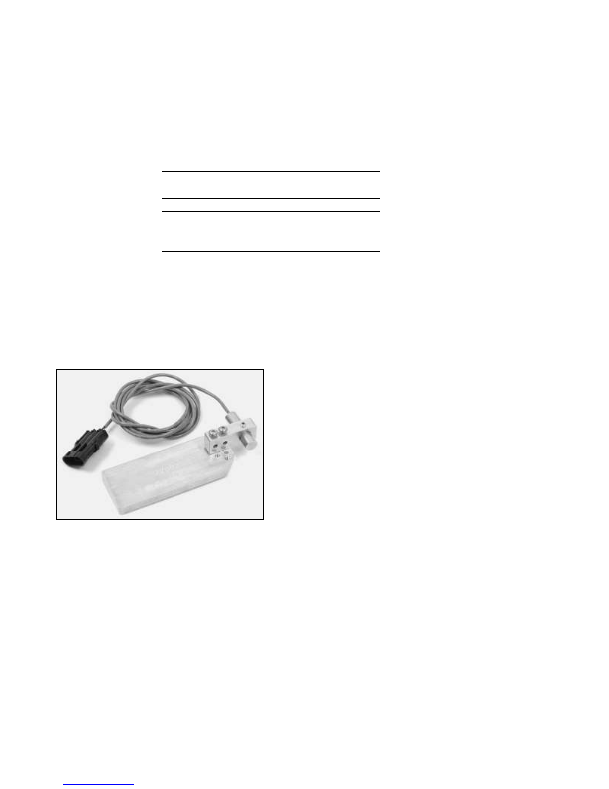
Figure 3. Universal Crank
Sensor Bracket
have better noise rejection. However Hall Effect sensors require adding a +12V power lead to it.
Electromotive can supply both Magnetic and Hall Effect sensors.
Table 1: Crank Trigger Specifications
3.3.3 Crank Sensor Installation
When installing the crank sensor, an appropriate bracket must be made to aim the sensor
at the trigger wheel. A good starting point for a magnetic sensor bracket is Electromotive part
number 210-72003, which is our universal sensor bracket (See Figure 3). If this part is not used
as a starting point, a custom bracket can easily be made. The most important things to
remember when fabricating a bracket are that it should be bolted directly to the engine
block, away from rotating steel or magnetic pieces, and should be nonferrous (not
attracted to magnets). This will keep the sensor and
trigger wheel vibrating together so the gap between the
two always stays the same. Variations in sensor gap
may cause erratic timing or false triggering of the
ignition. (This is the reason for not mounting the trigger
wheel to the outer ring of a harmonic damper.) As such,
any custom magnetic sensor bracket should be very
rigid. The sensor can be secured with either a set screw
or a clamping arrangement, as long as the
1/2” sensor is utilized (part number 250-72218). If the
smaller 3/8” sensor is used, a clamping arrangement
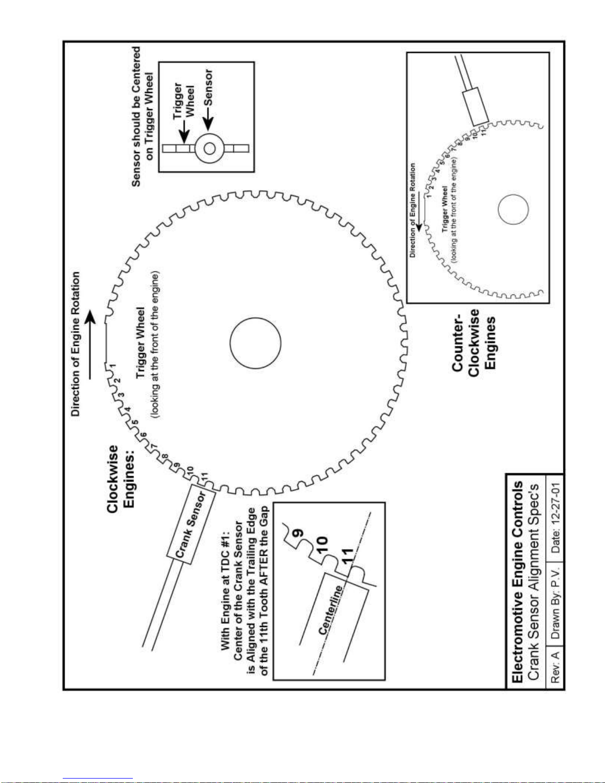
Once a sensor and trigger wheel are installed, they must be aligned such that the XDI200
computer knows where to locate Top Dead Center of the #1 cylinder (referred to as TDC #1).
Correct alignment necessitates that the center of the sensor must be aligned with the
trailing edge of the 11th tooth after the two missing teeth when the engine is at TDC #1 (see
the drawing at the end of this section). Aligning the magnetic sensor with anything other than
the 11th tooth will cause an ignition timing retard or advance, depending on the direction of the
misalignment. Each tooth represents six degrees, so if the sensor is aligned with the trailing edge
of the 12th tooth, the timing will be advanced by six degrees. Conversely, if the sensor is aligned
________________________________________________________________________
XDI200 Manual Version 0.1 - Page 13 - ©2017 Electromotive, Inc.
should be employed rather than a setscrew, as the
setscrews may crush the sensor. Hall effects sensors
are only available in ½” diameter. See Table 2 for the
appropriate magnetic sensor/trigger wheel combinations.

with the trailing edge of the 10th tooth, the timing will be retarded by six degrees. In the event that
the sensor is not aligned correctly, the WinTec software can be made to compensate by
manipulating the Tooth Offset Parameter, as outlined in the tuning section of this manual.
IMPORTANT NOTE :
Make sure that the Mag. Sensor harness is NOT routed near battery cables or other high
current leads or devices such as cooling fans, starter or alternator. Locating close to coil wires or
other power leads should be avoided.
________________________________________________________________________
XDI200 Manual Version 0.1 - Page 14 - ©2017 Electromotive, Inc.
3/8” Diameter
Chisel Point
Sensor
PN: 250-72212
1/2” Diameter
Flat Tip
Sensor
PN: 255-72218
½” Diameter
Flat Tip
Hall Effect
Sensor
All 120 (-4) Tooth
X
2-3/8” & 2-1/2”
60 (-2) Tooth
X
3-1/2” 60 (-2) Tooth
(below 6000rpm)
X
X
3-1/2” 60 (-2) Tooth
(Above 6000rpm)
X
X
Greater than 3-1/2”
60 (-2) Tooth wheels
X
X X
1 tooth Cam Wheel
X
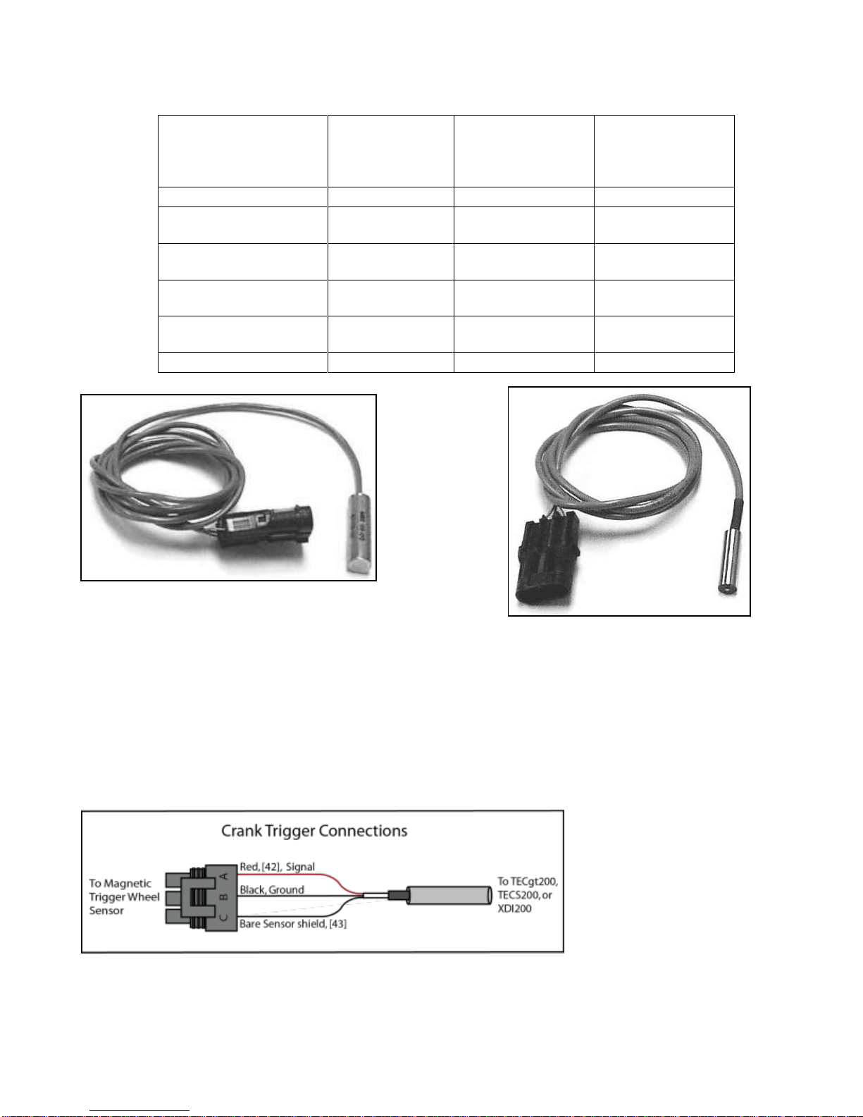
Figure 5. Electromotive 3/8” (9.53mm)
Table 2: Magnetic crank sensor selection. Note: use a clamping arrangement for securing 3/8” sensors,
rather than a setscrew. The ½” sensors can be secured with any clamping method.
Figure 4. Electromotive ½” (12.7mm)
crank sensor
3.3.4 Wiring a Magnetic Trigger Sensor
The magnetic sensor has three wires. The red wire is the signal from the sensor, the black
wire is the signal ground, and the bare wire is the shield. The harness has provisions for both a
crank and a cam sensor. The crank sensor cable must be used for all 60 (-2) or 120 (-4)
tooth trigger wheel inputs. It is not recommended to use a magnetic sensor on the cam trigger
wheel.
________________________________________________________________________
XDI200 Manual Version 0.1 - Page 15 - ©2017 Electromotive, Inc.

Figure 6: Wiring layout for crank and cam sensors. Note that the Cam Sensor is only used when full
cylinder to cylinder timing trim is needed. The wiring is the same if a Hall Effect sensor is used on the
crankshaft wheel.
3.3.5 Verifying Trigger Wheel Timing
The most important step in the trigger wheel installation process is to check the ignition
advance with a timing light. A timing indicator (pointer) should be attached to the engine block,
and it should point at a line on the crankshaft pulley or trigger wheel when the engine is at TDC
#1. When running the engine, verify that the timing value read by the timing light corresponds to
the timing value in the software’s engine monitor screen.
Use of a good-quality inductive timing light is recommended. DO NOT use a timing light
that goes between the spark plug and spark plug wire with a clamp probe. Dial-Back inductive
timing lights can be used, but will need to be dialed to DOUBLE the actual desired timing value
due to the waste-spark firing of the DFU coils. They are fooled into thinking that the timing is
twice as advanced as it actually is.
________________________________________________________________________
XDI200 Manual Version 0.1 - Page 16 - ©2017 Electromotive, Inc.
________________________________________________________________________
XDI200 Manual Version 0.1 - Page 17 - ©2017 Electromotive, Inc.

3.3.6 Camshaft- & Distributor-Mounted Trigger Setups
While crankshaft mounted triggers are preferred, it is sometimes easier to install a
camshaft- or distributor-mounted trigger wheel. For these cases in which the trigger wheel is
spinning at half the engine speed, a 120(-4) tooth trigger wheel is necessary. This wheel has
two sets of two missing teeth, spaced 180 degrees apart. As such, the input to the XDI200 is
identical to that of the crank-mounted 60(-2) tooth trigger wheel. Electromotive offers 120 (-4)
tooth wheels in 3.25” and 2.75” diameters.
It is often easy to use an old distributor rotor to serve as the mount for a 120(-4) tooth
trigger wheel. A simple nonferrous bracket would need to be fabricated to hold the sensor. The
3/8” chisel point sensor (PN: 250-72219) must be used on 120(-4) trigger wheels. As such, the
bracket for the sensor should use a clamping arrangement rather than a setscrew to hold the
magnetic sensor. Just like the crank-mounted trigger, the distributor/cam-mounted triggers
require the sensor to be aligned with the trailing edge of the 11th tooth after the two
missing teeth when the engine is at TDC #1. The same tolerances that apply to the
crankshaft-mounted trigger wheels (Table 1) apply to the camshaft-mounted trigger wheels as
well.
A Note on Engines with High-Overlap Camshafts:
If your engine is equipped with a camshaft that has early intake valve openings or very
long duration, you may experience backfiring through the throttle during starting. This is caused
by the intake valves beginning to open on the exhaust stroke. Since the spark plugs fire on both
the compression and the exhaust strokes, the spark on the exhaust stroke may cause unburned
fuel in the intake manifold to ignite, resulting in a backfire.
To remedy this situation, advance the “mechanical” timing by manipulating the DFU “A”
Trigger Wheel TDC Parameter. If your crank sensor is aligned with the 11th tooth of the trigger
wheel at TDC #1, setting the Tooth Offset to a number LOWER than 11 will add mechanical
advance. If the number “10” was set for the Tooth Offset, the mechanical timing would be
ADVANCED by 6 degrees (6 degrees per tooth). This would require that you subtract 6 degrees
from the values in your ignition advance table in WinTec to obtain your desired advance value.
That is, the timing table will have to read 30 degrees in order for the engine to operate at 36
degrees advance. See the Tuning Guide Section for more details.
3.3.7 Individual Cylinder trim application – Cam Synchronization
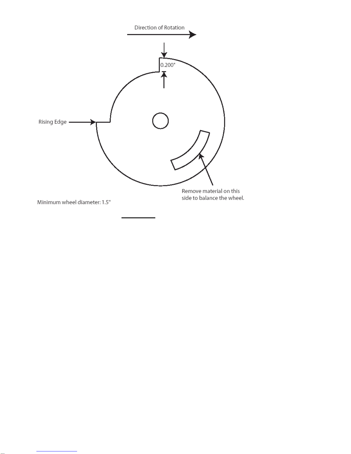
When individual cylinder advance angle trimming is desired, a once-per-engine-cycle
synchronization, or “sync,” pulse must be received by the ECU. Typically, the sync pulse is
generated by the installation of a 1-notch (or 1-tooth) trigger wheel onto the camshaft. A Hall
effect sensor is used as a triggering method. With this method, the tooth must pass by the
magnetic sensor between 180o and 6o before TDC Compression (not exhaust) of the number one
cylinder. See Figure 11 for installation details.
The XDI200 will only trigger off a rising voltage during the synchronization period
(between 180o and 6o BTDC compression). A rising edge occurs when the metal on the cam
trigger wheel becomes closer to the sensor. See Figures 8 and 9 for representative examples
and different cam trigger wheel designs, and their rising edge location.
________________________________________________________________________
XDI200 Manual Version 0.1 - Page 18 - ©2017 Electromotive, Inc.
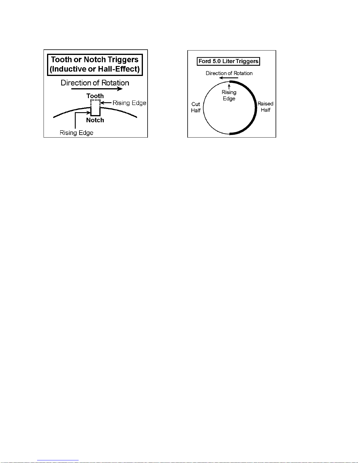
Figure 8. Tooth/Notch Triggers Figure 9. Ford “Half-Moon” Trigger
Due to high noise sensitivity of magnetic sensors, it is required to use a Hall Effect sensor
are with the XDI200’s sync pulse requirement. This would include most Hall effect, flying magnet
sensors. As long as the sensor outputs a rising voltage to the XDI200 between 180o and 6o
before TDC compression for the number one cylinder, it should work perfectly.
Terminal 39 on the ECU is used for cam sync inputs (as shown in Figure 6). If using a
Hall effect or other sensor type that is powered by +5Volts, be sure that the output signal from the
sensor is going into terminal 39. Keep in mind that when adapting an OEM cam trigger setup to a
XDI200, the wheel may need to be rotated to place the rising edge in the appropriate degree
window for the XDI200.
________________________________________________________________________
XDI200 Manual Version 0.1 - Page 19 - ©2017 Electromotive, Inc.
3.3.8 TDC Tooth Setup Software Adjustment Parameters
Figure 11:
Proper cam
trigger
installation. This
cam trigger
occurs approx.
90o BTDC
Compression on
the #1 cylinder
(as measured at
the crank). Note
the 87 degree
(as measured on
the cam wheel)
“window” in
which the rising
edge must occur.
So, you took a lot of time to install your trigger wheel, and now you realize that you didn’t
get the trailing edge of the 11th tooth to align with the center of the magnetic sensor with the
engine at TDC #1. What to do?
The WinTec4 software features a TDC setup parameter that allows users to manipulate
the TDC point for the trigger wheel. There are two adjustable parameters:
The default setting for DFU “A” TDC is 11, signifying TDC alignments with the 11th tooth. If you
are aligned with the 13th tooth at TDC, change this number to 13. Several late-model Boschequipped applications use our 60 (-2) tooth trigger wheel, but come from the factory with a
different TDC tooth alignment. Typically, these setups are referenced to the 14th tooth for TDC,
but you MUST confirm this on your application, since Bosch used a few different offsets through
the years.
(using the parameter “DFU “B” Trigger Wheel TDC”). This allows the user to define the odd-fire
ignition split that is present on the engine. Refer to the Tuning Guide Section to determine the
proper settings for this value.
overlap cams. Assuming the crank sensor is aligned with the 11th tooth at TDC, this can be done
by entering a value for the “Change DFU “A” Trigger Wheel TDC” that is LESS than 11. Each
tooth less than 11 represents 6 degrees of advance that is added to the Ignition Advance Table.
do this). Assuming the crank sensor is aligned with the 11th tooth at TDC, this can be done by
________________________________________________________________________
XDI200 Manual Version 0.1 - Page 20 - ©2017 Electromotive, Inc.
Change DFU “A” Trigger Wheel TDC
Change DFU “B” Trigger Wheel TDC
For all but the odd-fire applications, the adjustment is only present for the DFU “A” TDC.
Odd-Fire applications have the ability to move the TDC reference for the second DFU
Some applications may require more “mechanical timing” to compensate for large, high-
Some applications may require less “mechanical timing” (some rotary users may wish to

entering a value for the “Change DFU “A” Trigger Wheel TDC” that is MORE than 11. Each tooth
more that 11 represents 6 degrees of retard that is subtracted from the Ignition Advance Table.
If an odd-fire engine has the trigger wheel installed incorrectly, and the DFU “A” TDC
parameter is changed to compensate for the error, the “DFU “B” Trigger Wheel TDC” parameter
needs to be manipulated in the same amount. As an example, if the TDC for DFU “A” is at 11
and is moved to 10, the TDC for DFU “B” would need to be moved from 16 to 15.
The following pages outline the various situations that can be addressed through the TDC
software parameters.
Situation A
Problem:
Incorrect trigger wheel alignment results in undesired mechanical timing.
Solution:
With the engine at TDC #1, find the trigger wheel tooth that is aligned with the crank sensor.
Enter the number of this tooth into the TDC Tooth Alignment Parameter. The timing will be
shifted to make the Ignition Advance Table accurate.
Method:
The software will automatically RETARD the timing when a number GREATER THAN 11 is
entered into the TDC Tooth Alignment Parameter. The timing will be automatically ADVANCED
when a number LESS THAN 11 is entered.
Situation B
Problem:
The engine needs less mechanical advance, and the crank sensor is aligned with the 11th tooth.
Solution:
Enter in the number “12” to the TDC Tooth Alignment Parameter. The timing values will be
automatically RETARDED by 6 degrees. The Ignition Advance Table values will now be incorrect
(the displayed values will be 6 degrees higher than the actual advance).
Situation C
Problem:
The engine needs more mechanical advance, and the crank sensor is aligned with the 12th tooth
instead of the 11th.
Solution:
Enter in the number “11” to the TDC Tooth Alignment Parameter. The timing values will be
automatically ADVANCED by 6 degrees. The Ignition Advance Table values will now be incorrect
(the displayed values will be 6 degrees lower than the actual advance).
Note:
In the past, aligning the sensor with the 12th tooth would advance the mechanical timing by 6
degrees.
________________________________________________________________________
XDI200 Manual Version 0.1 - Page 21 - ©2017 Electromotive, Inc.
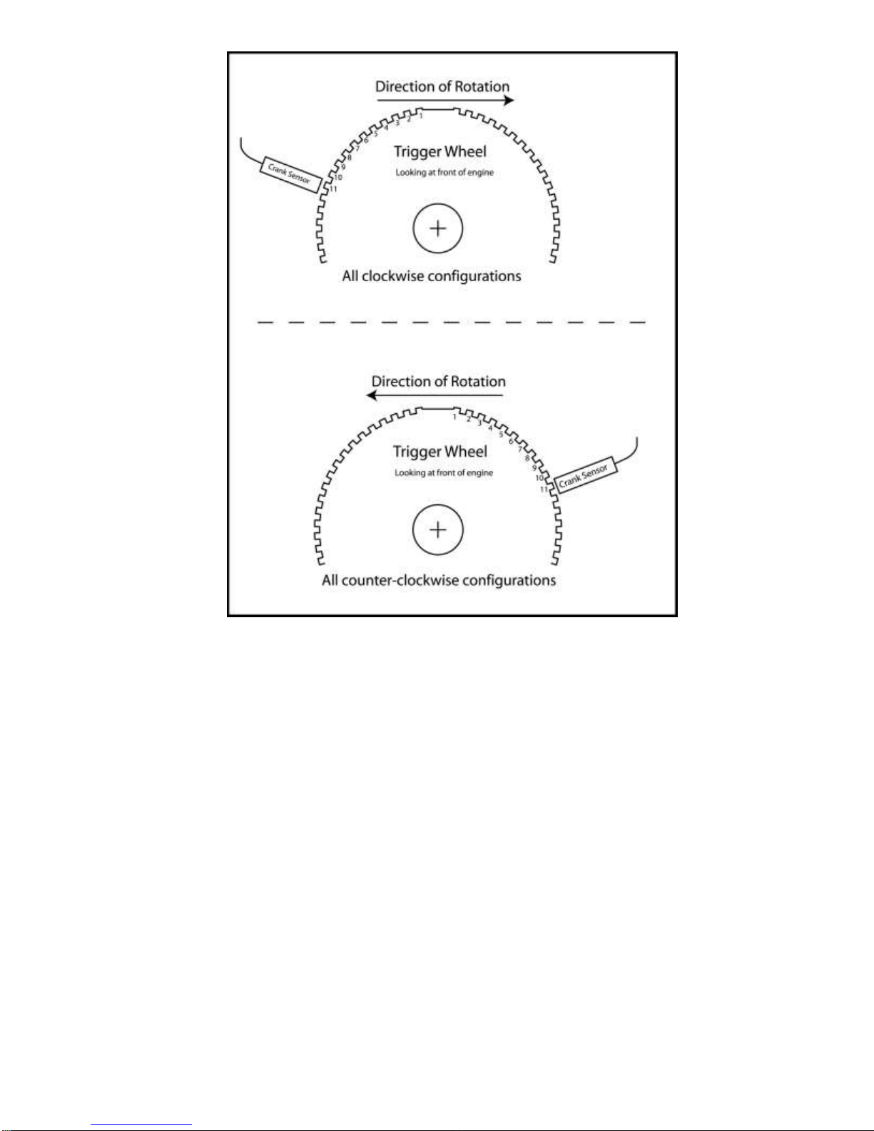
Figure 13 - TDC tooth for two possible scenarios.
________________________________________________________________________
XDI200 Manual Version 0.1 - Page 22 - ©2017 Electromotive, Inc.

In a normal scenario, not considering software manipulation, aligning the magnetic sensor
WARNING: Always disconnect the battery when doing ANY electrical work on
a vehicle. Use common sense when working around electrical systems,
particularly the XDI200 DFU coils. The voltage output of the coils can be well
over 40,000 Volts at a given instant.
with anything other than the 11th tooth will cause an ignition timing retard or advance, depending
on the direction of the misalignment. Each tooth represents six degrees, so if the sensor is
aligned with the trailing edge of the 12th tooth, the timing will be advanced by six degrees.
Conversely, if the sensor is aligned with the trailing edge of the 10th tooth, the timing will be
retarded by six degrees. If some ignition advance is required for easier starting (high
compression/radical cam timing engines, for example), aligning the sensor with the 12th or 13th
tooth will yield 6° or 12° (respectively) of advance during cranking. Also check that the sensor is
centered over the edge of the wheel.
4 Wiring the System
4.1 Introduction
The task of installing a XDI200 wiring harness may seem a bit intimidating at first.
However, by dividing the wiring installation into a few small jobs, it can be accomplished by most
installers in a reasonable amount of time.
4.1.1 Suggestions on Crimp Terminals…
When crimping terminals to the sensor wires, care must be taken to ensure that a proper
crimp is made. Improper crimps can lead to terminal failure and wire fatigue. To crimp properly,
we recommend using a high-quality ratcheting crimp tool (such a tool is available from
Electromotive). In the absence of a good crimp tool, the terminals can be soldered. Care should
be taken to make absolutely certain that the solder penetrates the terminal and gets to the wire.
There are two main crimp styles used with the XDI200 sensors: Metri-Pack and WeatherPack. Metri-Pack terminals have two crimp areas. One area crimps to the bare (stripped) wire
and provides the electrical connection, and the other area crimps to the un-stripped wire housing
to provide a strain relief. Metri-Pack connectors are pull-to-seat.
Weather-Pack terminals also have two crimp areas, but instead of one area acting as a
strain relief, it is used to hold the connector seal in place. Therefore, when crimping a WeatherPack terminal, always insert the cable seal before crimping. Weather-pack connectors are pushto-seat.
Note : Soldered terminals will not tolerate much flexing. They may break if too much
movement is allowed.
The main XDI200 connector is a Molex 123 type connector.
Please go to this internet link and down load this document:
http://www.molex.com/pdm_docs/as/AS-34566-001.pdf
It has important information on handling the XDI200’s new Molex connector.
________________________________________________________________________
XDI200 Manual Version 0.1 - Page 23 - ©2017 Electromotive, Inc.

4.2 Wiring ECU & Main Power
The two red/white (red with white tracer) wires on pins 33 and 53 are the switched ignition
power. For redundancy, both red/white wires must be connected to the same switched +12V
circuit. The ground wire is 12awg and on pin 73. The reason for the larger/thicker size of the
ground wire is that the ECU is mainly in charge of switching the GROUNDS, not the +12 Volt
power. As an example, coil outputs are all pull-to-grounds. The XDI200 does not use constant
+12 Volt power.
Both red/white 18awg wires, [33] and [53], must be connected to the ignition switch. The
black 12awg wire, [73] of the connector is connected to full time battery negative. See Figure 15
for a wiring diagram.
If you are using the XDI200 Power Harness, refer to the next section on installing the
Switched +12 Volt Input into the Power Harness.
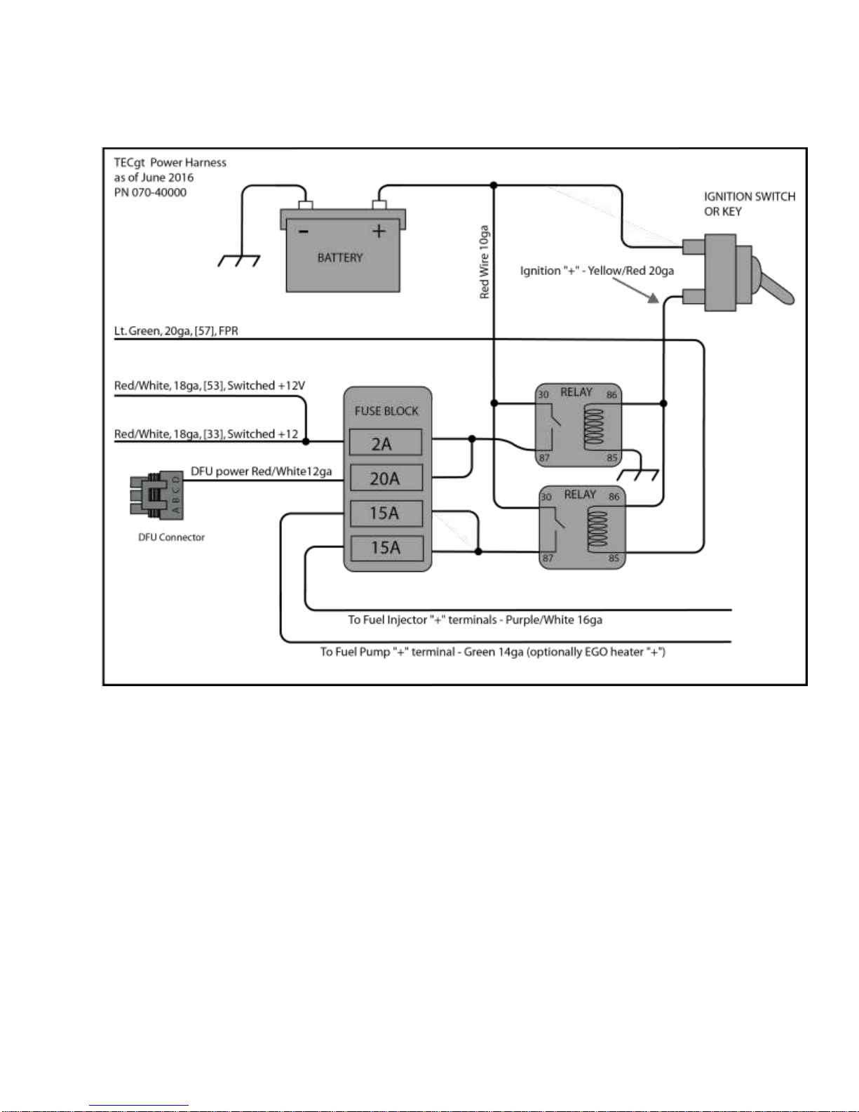
4.2.1 Power Harness Installation
Electromotive’s Power Harness (PN 070-40000) for the XDI200 is capable of supplying the
+12Volt high-amperage power required to run the DFU’s, EGO sensor heater and fuel pump.
Included in the harness is a fuse block with four fuses (ignition, DFU’s, and Fuel Pump are fused)
and two relays to switch the power. Our custom harnesses are all built with the power harness
pre-installed, so wiring them is even more straightforward. Figure 15 gives an example of a
typical Power Harness installation.
There are three breakouts in the Power Harness:
ECU Connections
Power Inputs
Power Outputs (w/ switched voltage input)
ECU Connections
The XDI200 Connections are color-matched to the XDI200 harness.
Light Green 20awg Wire: Connects to [57] (Fuel Pump Relay Ground)
Yellow (from power harness) 20awg Wire: Connects to Switched +12v input
Power Inputs
The Power Inputs are color coded in standard fashion:
Two Red/White 18ga Wire in parallel, pin [33] and [53]: connect to (Switched +12V
input)
Black 12awg Wire, pin [73]: Connect to Vehicle Battery - minus
Power Outputs (w/ switched voltage input)
The power outputs provide power for the DFU’s, EGO sensor heater, and Fuel Pump. The
switched voltage input is used to turn on the XDI200 ECU, and should be wired to a +12Volt
source that is activated with the ignition key.
Purple/White Stripe 16awg: Used for fuel pump if needed
Red/White Stripe: DFU Power (pin “D” on DFU’s)
Green 16awg: Fuel Pump Positive and EGO Sensor Heater Positive
Yellow 18awg: Switched +12 Volt Input (for XDI200 turn-on request)
________________________________________________________________________
XDI200 Manual Version 0.1 - Page 24 - ©2017 Electromotive, Inc.
The Wiring Diagrams in the DFU wiring section of this manual show the terminals on which the
power should be brought in. Any reference to fusing the power source in these sections is
unnecessary when using the Power Harness, since the connections are already fused.
Figure 15. XDI200 Power Harness (PN: 070-40000).
4.3 Wiring Ignition Coil Primary Sides
4.3.1 Introduction
The XDI200 has the ability to operate either the older style standard ignition coils or more
recent Driver on Coil (DOC) coils. If DOC coils are selected, the customer must set a fixed dwell
time in the calibration. Failure to select DOC and set a dwell time will cause damage to the DOC
coils. Use the section directly below to wire Electromotive’s standard DFU’s. Jump to the next
section for instructions on wiring DOC logic driven coils.
________________________________________________________________________
XDI200 Manual Version 0.1 - Page 25 - ©2017 Electromotive, Inc.

4.3.2 Standard Direct Fire Units, DFU’s
DFU’s are made by Electromotive in two variants: 2-coil and 3-coil. Each coil drives two
spark plugs in waste-spark ignition setups. Eight cylinder engines will use two 2-coil DFU’s. 2rotor engines will use 4 single tower coil units. Two cycle applications will use single tower coils
as well.
The DFU’s are driven by a 12-volt charging system housed in the XDI200 ECU. For the
Electromotive DFU wiring requirements, refer to Figures 25 below.
4.3.3 Wiring Standard DFU’s Coils
The DFU connectors use pull-to-seat terminals. DO NOT crimp the terminals onto the
wires until you have fed the wires through the connector!
Before wiring the DFU’s, you must select the right configuration below. Each standard
Electromotive DFU has a 4 pin connector on it.
2-Coil DFU’s (Part Number 070-33400)
The 2-coil DFU’s utilize three of the four terminals in their yellow connector. Here is the pin out:
Terminal A Ground Pulse for Coil A
Terminal B Ground Pulse for Coil B
Terminal C Unused
Terminal D Full-Time +12 Volt Source (9 amps)
On a standard inline 4-cylinder four-stroke application, this DFU will be used. On 8 cylinder or
dual-plug 4-cylinders, two of these DFU’s will be used.
3-Coil DFU’s (Part Number 070-33600)
The 3-coil DFU’s utilize all four of the terminals in the yellow connector. Here is the pin out:
Terminal A Ground Pulse for Coil A
Terminal B Ground Pulse for Coil B
Terminal C Ground Pulse for Coil C
Terminal D Full-Time 12 Volt Source (9 amps)
On a standard 6-cylinder even-fire application, this DFU will be used.
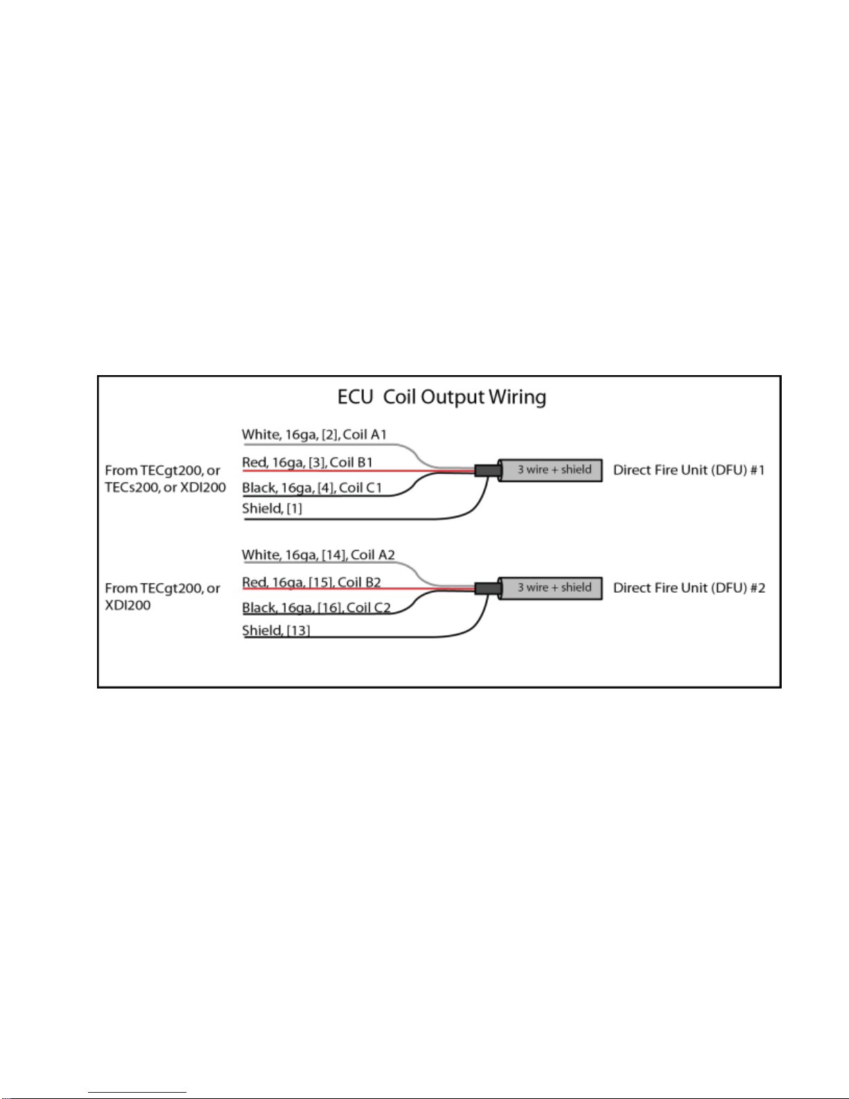
The XDI200 harness has two cables for the DFUs. Both cables have three 16awg wires
with a shield.
6 or 4 cylinder engines with single spark plugs use only the first cable, 8, 12 and Dual plug
engines use both cables
4- Coil DFU’s (Part Number 070-33400)
The 4-coil DFU is actually two 2-coil DFU’s. When this part number is specified, two 070-33400
DFU’s will be used. The first DFU should be wired in the same manner as part number 070-
33400.
The first step in wiring the DFU’s is to install the ground wire. The DFU’s come from our factory
with a ground wire pre-installed on a tapped, un-anodized hole. This wire MUST be connected to
chassis/battery ground. FAILURE TO DO SO MAY RESULT IN SEVERE ELECTRICAL SHOCK TO
THE USER!! Electrical shock will occur if the DFU is not grounded, and someone touches it while
________________________________________________________________________
XDI200 Manual Version 0.1 - Page 26 - ©2017 Electromotive, Inc.
touching chassis ground (with the engine running). If desired, the ground wire may be relocated
elsewhere on the DFU chassis. However, you will need to scrape off the anodization from the
chassis at the point of contact, since the anodizing acts as an electrical insulator. Also, loose coil
screws may cause an electrical shock as well, since they must be grounded to the case at all
times. Always make sure that both the coil screws and the ground wire are securely fastened.
After the DFU has been grounded, the rest of the wiring may begin. The DFU’s come
shipped with the appropriate connectors. Terminal D on all DFU’s should be connected to a
FUSED 12 VOLT SOURCE that can pull 9 AMPS of current. In the wiring harness, the outputs for
Coils A, B, and C are routed in the same shielded-cable housing. On an 8 cylinder, the outputs
for DFU 2 (A2, B2) are routed in a separate shielded-cable housing. These are all 9amp pull-toground outputs; that is, they create a ground path every time a coil charges. When the coils fire,
the outputs “float,” with no connection to ground or power. If the wires need to be spliced or
lengthened, 16awg wire should be used. See Figure 25 for details on the coil outputs in the
wiring harness. The XDI200 has both standard DFU coil outputs and logic outputs. When using
the Standard DFU outputs showed below, remove or tape off the DOC wires [5,6,7 and 10,11,12].
Figure 25: ECU Coil Output Wires (note: shield wire is connected inside the XDI200 unit, not connected at
the coils).
The DFU chassis MUST be grounded. A ground wire must be connected to battery
negative, or to a good chassis ground. FAILURE TO GROUND THE DFU’S MAY
RESULT IN SEVERE ELECTRICAL SHOCK! Also, poorly grounded DFU’s may
result in poor engine performance, and can cause engine damage!! Use the drilled
and tapped hole next to the yellow connector for the ground wire. If desired, the
unit may instead be grounded at one of the four bolt holes. However, you will
need to scrape off the anodizing under the bolt head. The anodizing is an
electrical insulator, so unless it is scraped down to bare aluminum, it will not provide
________________________________________________________________________
XDI200 Manual Version 0.1 - Page 27 - ©2017 Electromotive, Inc.
WARNING:
a good connection to ground. If more than one DFU is used on a vehicle, each one
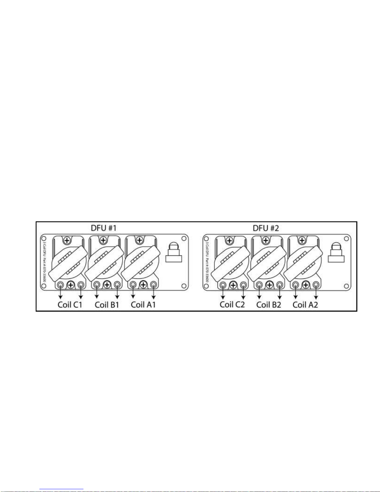
Figure 26 : Coil notation
will require its own ground wire.
Additionally, make sure that the coil screws are fully tightened at all times!!
4.3.4 Spark Plug Wiring High Voltage Side
The coils fire in a specific order for each engine configuration. The proper coil must be
connected to the correct cylinder in the firing order.
Coil Notation
The following notation is used when referring to coils. A letter and a number are combined
to identify a coil. The letter refers to the coil location on the DFU. The coil located closest to the
connector is Coil A. The coil next to it is Coil B. If the DFU contains three coils, the last coil is
Coil C. The number identifies the DFU that the coils are on. In an engine configuration using
only one DFU, the number following the letter is 1. Coil notation is shown in Figure 26.
Note: Each coil has two towers for spark plug wires. The towers are identical and should be
thought of as the same coil. For example, if the engine setup guide refers to cylinder 1 connected
to Coil A1 and cylinder 6 connected to Coil A1, you can connect your spark plug wires for the
respective cylinders to EITHER tower.
Figure 26 shows a configuration using two 3-coil DFU’s. If you are using 2-coil DFU’s the
numbering is the same except there is not C1 and C2. If your application requires only one DFU,
then A2, B2, and C2 will not be needed.
________________________________________________________________________
XDI200 Manual Version 0.1 - Page 28 - ©2017 Electromotive, Inc.
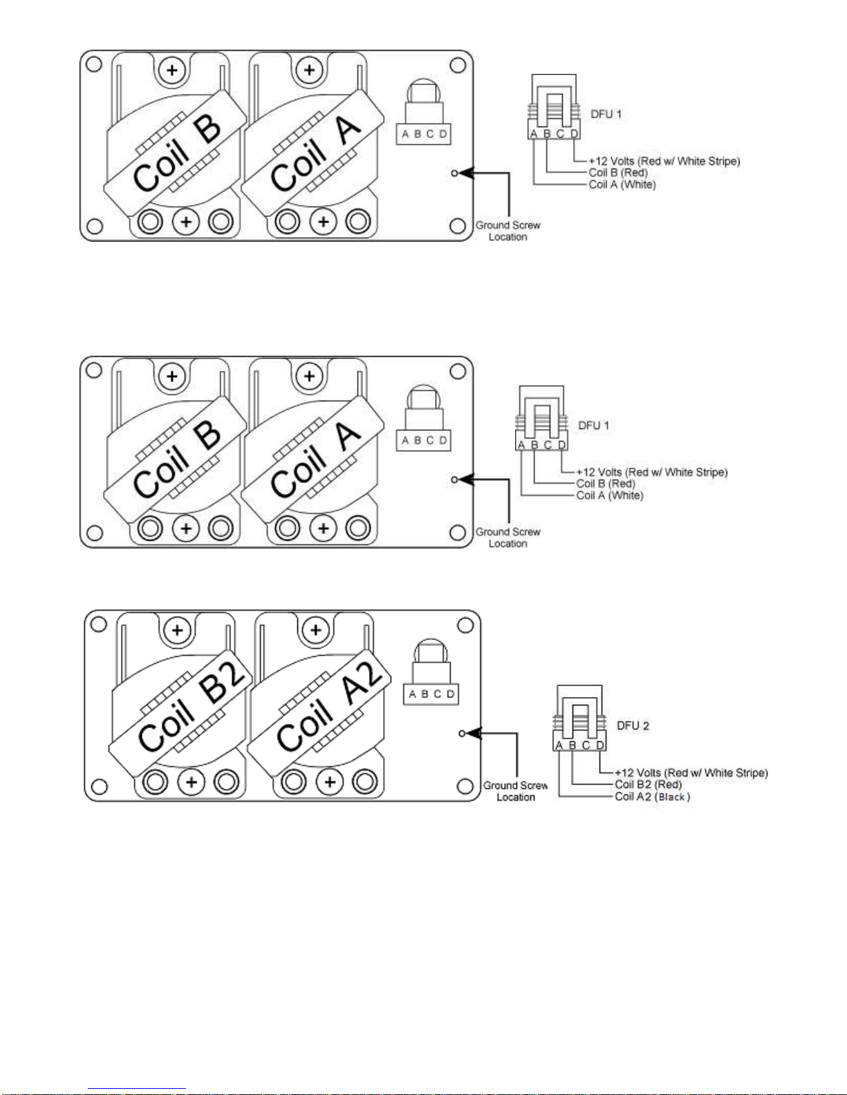
Figure 27. 4-Cyl DFU Setup
1st DFU
2nd DFU
Figure 28: 8-Cyl and 4-cyl Dual Plug DFU Setup. Note that the 2nd DFU coils will not be
labeled C and D from Electromotive. When the 2nd DFU is wired as shown, the coil labeled “A”
will fire coil output “A2.” The coil labeled “B” will fire coil output “B2.”
________________________________________________________________________
XDI200 Manual Version 0.1 - Page 29 - ©2017 Electromotive, Inc.
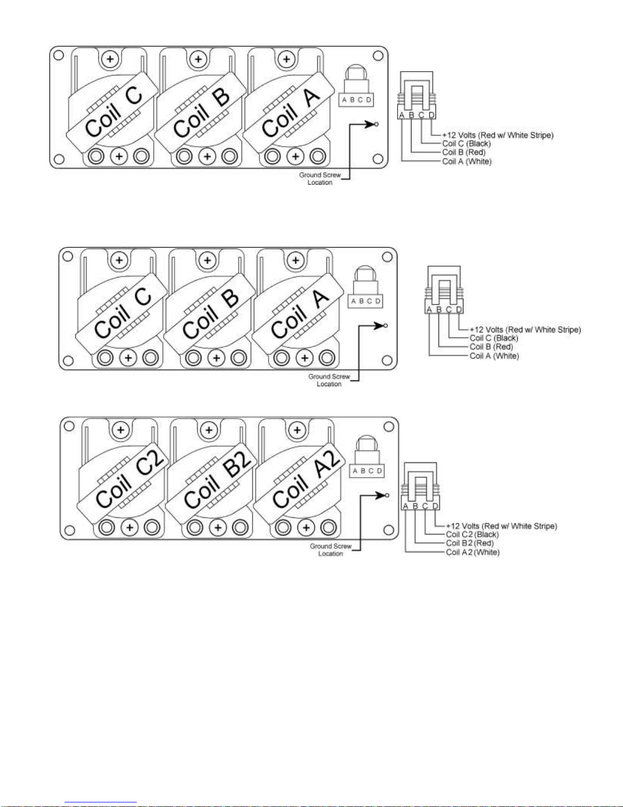
Figure 29: 6-Cyl DFU Setup
1st DFU
2nd DFU
Figure 30: (The above picture is from a twin-plug 6 Cyl.), if running a V8 the first DFU will have
coils A1, B1 the second DFU will have coils A2, B2.
4.4 Ignition Firing Order
For the engine to run correctly, the coils must be connected to the appropriate cylinders.
Since the Electromotive DFU’s utilize waste-spark coils, it is necessary to know the firing order of
an engine to determine which cylinders should be paired together.
________________________________________________________________________
XDI200 Manual Version 0.1 - Page 30 - ©2017 Electromotive, Inc.
 Loading...