


Table of Contents
Terms and Conditions......................................................................... 5
Electromotive Product Warranty ...............................................................................................5
Warranty Replacement ..............................................................................................................5
Warranty Coverage....................................................................................................................5
Length of Warranty....................................................................................................................5
Who the Warranty Protects........................................................................................................5
Warranty Exclusions..................................................................................................................6
How to Obtain Warranty Service ..............................................................................................6
Limitation of Implied Warranties ..............................................................................................7
Exclusion of Damages ...............................................................................................................7
Forward................................................................................................ 8
A. Installing the TECgt System.......................................................... 9
A.1. How it All Works: The Two Pages You Need to Read ....................................................9
A.2. Pre-Installation Checklist................................................................................................10
A.3. Mounting the Main Computer and DFU.........................................................................11
A.4. Trigger Wheel and Sensor Installation ...........................................................................12
A.4.a. Crankshaft Trigger Installation for 60(-2) Tooth Wheel .............................................12
A.4.b. Magnetic Crank Sensor Installation.............................................................................13
A.4.c. Wiring the Magnetic Sensor ........................................................................................15
A.4.d. Verifying Trigger Wheel Timing.................................................................................15
A.4.e. Camshaft- & Distributor-Mounted Trigger Setups......................................................17
A.4.f. Full Sequential Applications – Cam Synchronization..................................................17
A.4.g. TDC Tooth Setup Software Adjustment Parameters...................................................19
A.5. Wiring the TECgt............................................................................................................21
A.5.a. TECgt - Main Power Connections ...............................................................................21
A.5.b. Power Harness Installation ..........................................................................................21
A.5.c. Wiring the Fuel Injectors .............................................................................................23
A.5.d. Wiring the DFU’s ........................................................................................................24
A.5.e. Wiring the Engine Sensors...........................................................................................24
B. Tuning Guide ............................................................................... 25
Introduction..............................................................................................................................25
B.1. Adjusting the Timing Advance .......................................................................................25
B.2. Establishing Proper Starting Enrichments ......................................................................26
B.3. Getting the Engine to Idle ...............................................................................................27
B.4. Establishing Proper Acceleration Enrichments...............................................................27
B.5. Adjusting the VE Table...................................................................................................28
B.6. Using TPS/MAP Blend...................................................................................................29
B.7. Tuning for Cold Engines and Cold Weather...................................................................29
B.8. Tuning the Idle Air Control Motor .................................................................................30
B.8.a Configuring the New Electromotive Idle Speed Control .............................................30
B.8.b. Idle Speed primer ........................................................................................................31
B.8.c. Getting Started..............................................................................................................31
B.8.d. Error Sensitivity ...........................................................................................................32
B.8.e. RPM Rate-of-Change Sensitivity.................................................................................32
B.8.f. Wiring a 2-wire IAC:....................................................................................................33
______________________________________________________________________________________
TECgt Manual Version 2.0 - Page 1 - ©2008 Electromotive, Inc.

B.8.g. Wiring a 3-wire IAC: ...................................................................................................33
B.9. Tuning the Knock Control ..............................................................................................34
B.10. Using the Injector Trims ...............................................................................................34
B.11. Using the Ignition Advance Trims................................................................................35
B.12. Tuning the EGO Sensor ................................................................................................35
C. Direct Fire Units (DFU’s) ........................................................... 36
Introduction..............................................................................................................................36
C.1. Wiring the DFU’s............................................................................................................37
C.2. DFU to Spark Plugs ........................................................................................................38
C.3. Spark Plug Wire Routing ................................................................................................40
C.3.a. Common Engine Setups ...............................................................................................41
C.3.b. Special Note for Coil-Per-Plug Applications...............................................................41
C.4. Coil and Injector Firing Schemes....................................................................................42
C.4.a. Injector and Coil Firing Patterns for EVEN-FIRE Engines.........................................42
C.4.b. Injector and Coil Firing Patterns for ROTARY Engines.............................................43
C.4.c. Injector and Coil Firing Patterns for 2-CYCLE Engines .............................................43
C.4.d. Injector and Coil Firing Patterns for ODD-FIRE Engines...........................................43
C.4.e. Examples of Typical Engine Setups.............................................................................44
C.5. Common Firing Orders ...................................................................................................46
C.5.a. To find the TDC Event Order : ....................................................................................47
C.5.b. TDC Tooth for DFU “2” needed for an Odd-Fire Engine: ..........................................47
C.5.c. Harley-Davidson Applications.....................................................................................47
C.6. Rotary Engines................................................................................................................47
C.7. Dual Plug Engines...........................................................................................................48
C.8. Spark Plug Wire Selection ..............................................................................................48
C.9. Spark Plug Selection .......................................................................................................49
D. Fuel Injector Configurations ...................................................... 50
D.1. High vs. Low Impedance Injectors .................................................................................50
D.2. Injector Firing Schemes ..................................................................................................52
D.2.a. Staged Injection............................................................................................................52
D.2.b. Throttle Body Injection (TBI)......................................................................................53
D.2.c. Phase-Sequential Injection...........................................................................................54
D.2.d. Full Sequential Injection..............................................................................................55
D.2.e. Rotary Engine Injection ...............................................................................................56
D.3. Injector Wiring................................................................................................................56
D.4. Fuel Injector Pulse Width Derivation .............................................................................57
D.4.a. Introduction..................................................................................................................57
D.4.b. Time on for One Gama (TOG) ....................................................................................59
D.4.c. Injector Offset Time (IOT) ..........................................................................................62
D.4.d. Volumetric Efficiency Table Corrections....................................................................64
D.4.e. TPS/MAP Blend Corrections.......................................................................................65
D.4.f. Oxygen Sensor Corrections..........................................................................................67
D.4.g. Warm-Up Enrichments (Coolant Temperature-Based) ...............................................69
D.4.h. Manifold Air Temperature Enrichments......................................................................70
D.4.i. Throttle Position Sensor and MAP Enrichments..........................................................70
D.4.j. Starting Enrichments ....................................................................................................72
D.4.k. Battery Voltage Compensation....................................................................................73
D.4.l. Deceleration Fuel Cut-Off ............................................................................................73
D.4.m. Summary.....................................................................................................................74
______________________________________________________________________________________
TECgt Manual Version 2.0 - Page 2 - ©2008 Electromotive, Inc.

E. Fuel System .................................................................................. 74
E.1. Injector Sizing .................................................................................................................75
E.2. Fuel Pump Selection........................................................................................................79
E.3. Fuel Pressure Regulator Selection...................................................................................79
F. TECgt Output Functions and Wiring ....................................... 80
F.1 Idle Air Control Motor .....................................................................................................80
F.2. Tachometer Output..........................................................................................................82
F.3. The Fuel Pump Relay Output ..........................................................................................82
CAUTION: ..............................................................................................................................83
G. TECgt Input Functions and Wiring ........................................ 84
G.1. The Manifold Air Pressure (MAP) Sensor C B A .......................................................84
G.2. Throttle Position Sensor..................................................................................................87
TPS Functionality and Wiring.................................................................................................88
G.3. Coolant Temperature Sensor ..........................................................................................89
G.4. Manifold Air Temperature Sensor..................................................................................91
G.5. The Exhaust Gas Oxygen Sensor....................................................................................92
Mounting the Sensor................................................................................................................92
G.6. Wideband O2 Sensor ......................................................................................................94
FAQ’s and Troubleshooting Tips: ...........................................................................................95
G.7. Knock Sensor..................................................................................................................96
H.1. The General Purpose Inputs (GPI’s) and General Purpose Outputs
(GPO’s) or GP I/O’s.......................................................................... 97
H.1.a. Available General Purpose Input (GPI) Functions : ...................................................98
H.1.b. Wiring the GPI’s..........................................................................................................99
H.1.c. GP I/O Wiring Harness Layout..................................................................................100
H.2. General Purpose Output (GPO) functions : ..................................................................101
H.2.a. Available GPO Functions ..........................................................................................101
H.2.b. Wiring the GPO’s: .....................................................................................................102
I. Diagnostics................................................................................... 104
I.1. Trouble Codes from the LED’s Mounted on the TECgt ................................................104
I.2. Trouble Codes from the Check Engine Output ..............................................................105
Trouble Code Descriptions ....................................................................................................106
I.2.a. Using the Trouble Codes .............................................................................................107
I.2.b. Wiring the Check Engine Light...................................................................................108
J. Data logging with the TECgt..................................................... 108
J.1. PC-Based Data logging ..................................................................................................109
J.2. On-Board Data logging ...................................................................................................109
K. Rev Limiters .............................................................................. 109
K.1. Valet Mode Rev Limiter...............................................................................................110
K.2. Secondary Rev Limiter : ...............................................................................................110
K.3. Primary Rev Limiter :...................................................................................................110
L. Timing Control ........................................................................... 110
L.1. Zero degree advance......................................................................................................110
L.2. 3-stage coil cut ..............................................................................................................110
L.3. FUEL CONTROL .........................................................................................................111
L.3.a. No Fuel Cut ................................................................................................................111
L.3.b. Fuel Cut ......................................................................................................................111
______________________________________________________________________________________
TECgt Manual Version 2.0 - Page 3 - ©2008 Electromotive, Inc.

L.3.c. Progressive Fuel Cut...................................................................................................111
M. Troubleshooting........................................................................ 111
M.1. Air, Fuel, and Spark .....................................................................................................111
M.2. Starting Problems.........................................................................................................111
M.2.a. Air-Related Starting Problems ..................................................................................111
M.2.b. Fuel-Related Starting Problems ................................................................................112
M.2.c. Spark-Related Starting Problems ..............................................................................112
N.1. Idling Problems.............................................................................................................113
N.1.a. Air-Related Idling Problems ......................................................................................113
N.1.b. Fuel-Related Idling Problems ....................................................................................113
N.1.c. Spark-Related Idling Problems ..................................................................................113
O.1. Low-, Medium-, and High-Load Problems ..................................................................113
O.1.a. Air-Related Load Problems .......................................................................................113
O.1.b. Fuel-Related Load Problems .....................................................................................114
O.1.c. Spark-Related Load Problems ...................................................................................114
P.1. Summary of Troubleshooting Topics............................................................................114
Appendix I. Electromotive TECgt ECU Specifications .......................................................114
OUTPUTS .............................................................................................................................114
INPUTS .................................................................................................................................115
Tuning Features .....................................................................................................................116
Supported Engine Management Configurations....................................................................117
Data logging Features............................................................................................................117
Physical Dimensions..............................................................................................................117
Environmental Considerations...............................................................................................118
PC Requirements ...................................................................................................................118
Appendix II. Electromotive Trigger Wheel Availability......................................................118
Appendix III. Secondary Coil Polarity for Redundant Ignition Applications......................120
Appendix IV. TECgt Custom Harness Specification Sheet .............................................121
Appendix V. TECgt Custom Harness Spec. Sheet continued : ........................................122
Software Coding Information ................................................................................................123
Firmware Coding Information...............................................................................................123
Software Upgrade Procedure.................................................................................................123
Firmware Upgrade Procedure................................................................................................124
Appendix VI. TECgt
Gray Connector......................................................................................................................125
Appendix VII. TECgt Wiring Harness Layout.................................................................127
Appendix VIII. TECgt Power Harness Schematic ..........................................................128
Connector Pin Out Summary.............................................................125
______________________________________________________________________________________
TECgt Manual Version 2.0 - Page 4 - ©2008 Electromotive, Inc.

Terms and Conditions
Electromotive Product Warranty
Only products Manufactured by Electromotive are covered by Electromotive’s limited warranty for
a period of one-year from date of shipment by Electromotive.
Products not manufactured by Electromotive are expressly excluded from any consideration under these
terms – for information regarding products not manufactured by Electromotive you must contact the
specific product’s manufacturer.
Whenever possible, Electromotive attempts to replace defective products rather than repair them.
Replacement puts the "Customer First" and offers many benefits over repair; the greatest benefit being the
timeliness of the replacement process. However, in some cases, replacement with a ‘like new’ refurbished
product is not possible, and a warranty repair situation occurs. In these situations, Electromotive strives to
keep our repair times to a minimum (on average 2 to 3 business days upon receipt - excluding the necessary
shipping time). Customers should follow the appropriate steps outlined below to initiate a warranty
replacement or repair.
Warranty Replacement
Contact Electromotive Technical Support at 1-703-331-0100 9am to 5pm Eastern Time. The
customer must have the serial number and original proof-of-purchase available. Electromotive’s Technical
Support staff will attempt to help you correct any minor issues that might be causing the problem. If we are
unable to fix the issue to your satisfaction, a return merchandise authorization (RMA) number will be
issued. Under our Warranty program, Electromotive will typically ship the customer a replacement unit on
the same day the defective product arrives.
The replacement product will assume the remainder of your original product's warranty or 90 days,
whichever is greater.
Warranty Coverage
Electromotive warrants its products to be free from defects in material and workmanship during the
warranty period. If a product proves to be defective in material or workmanship during the warranty period,
Electromotive will, at its sole option, repair or replace the product with a similar product. Replacement
product or parts may include remanufactured or refurbished parts or components.
Length of Warranty
Electromotive products are warranted for one (1) year parts and one (1) year labor. Warranty begins
upon date of shipment from Electromotive.
Who the Warranty Protects
This warranty is valid only for the purchaser from Electromotive.
______________________________________________________________________________________
TECgt Manual Version 2.0 - Page 5 - ©2008 Electromotive, Inc.

Warranty Exclusions
1. Any product, on which the serial number has been defaced, modified or removed.
2. Damage, deterioration or malfunction resulting from:
A. Accident, misuse, neglect, fire, water, lightning, or other acts of nature, unauthorized
product modification, or failure to follow instructions supplied with the product.
B. Repair or attempted repair by anyone not authorized by Electromotive.
C. Any damage of the product due to shipment.
D. Removal or installation of the product.
E. Causes external to the product, such as electric power fluctuations or failure.
F. Use of supplies or parts not meeting Electromotive’s specifications.
G. Any other cause, which does not relate to a product defect.
3. Removal, installation, and set-up service charges.
4. Shipping Charges.
5. Any warranty of merchantability, express or implied, is excluded except as otherwise set forth
herein.
6. There are no warranties that extend beyond the description on the face of this document.
7. There are no warranties of fitness for a particular purpose except as stated on the face of this
“Electromotive Product Warranty”.
8. Any and all oral warranties are excluded and will not be honored.
9. Consequential damages will not be covered by this warranty.
How to Obtain Warranty Service
1. For information on warranty service, contact your Electromotive Value Added Dealer or call
Electromotive Technical Support at 1-703-331-0100 from 9am to 5pm Eastern Time Monday
through Friday - e-mail [support@electromotive-inc.com]. To obtain warranty service, you will
be required to provide:
a. Original dated sales receipt
b. Your name
c. Your address
d. The serial number of the product
e. A description of the problem
f. Contact information (daytime phone number or email address)
2. Take or ship the product in the original or a suitable replacement container to:
______________________________________________________________________________________
TECgt Manual Version 2.0 - Page 6 - ©2008 Electromotive, Inc.
Electromotive, Inc.
9131 Centreville Road
Manassas VA 20110

Limitation of Implied Warranties
THERE ARE NO WARRANTIES, EXPRESS OR IMPLIED, WHICH EXTEND BEYOND
THE DESCRIPTION CONTAINED HEREIN INCLUDING THE IMPLIED WARRANTY OF
MERCHANTABILITY AND FITNESS FOR A PARTICULAR PURPOSE.
Exclusion of Damages
ELECTROMOTIVE’S LIABILITY IS LIMITED TO THE COST OF REPAIR OR
REPLACEMENT OF THE PRODUCT. ELECTROMOTIVE SHALL NOT BE LIABLE FOR:
1. DAMAGE TO OTHER PROPERTY CAUSED BY ANY DEFECTS IN THE
PRODUCT, DAMAGES BASED UPON INCONVENIENCE, LOSS OF USE OF
THE PRODUCT, LOSS OF TIME, LOSS OF PROFITS, LOSS OF BUSINESS
OPPURTUNITY, LOSS OF GOODWILL, INTERFERENCE WITH BUSINESS
RELATIONSHIPS, OR OTHER COMMERCIAL LOSS, EVEN IF ADVISED OF
THEIR POSSIBILITY OF SUCH DAMAGES.
2. ANY OTHER DAMAGES, WHETHER INCIDENTAL, CONSEQUENTIAL OR
OTHERWISE.
3. ANY CLAIM AGAINST THE CUSTOMER BY ANY OTHER PARTY.
4. SHIPPING CHARGES.
______________________________________________________________________________________
TECgt Manual Version 2.0 - Page 7 - ©2008 Electromotive, Inc.

Forward
The TECgt Total Engine Control system is the latest ignition system in the expanded line of ultrahigh resolution engine management systems from the company that revolutionized engine management
over twenty years ago. The TECgt can be configured to control virtually any 1-, 2-, 3-, 4-, 6-, or 8
cylinder engine, as well as 1 or 2-rotor rotary engines, and dual plug 4 cylinder. The heart of the TEC
series of engine management systems has always been a high-resolution ignition, which offers incredibly
precise ignition timing even at the highest acceleration rates. The TECgt continues this tradition; only
what was once done with an analog ignition circuit is now done with a high-speed microprocessor. Direct
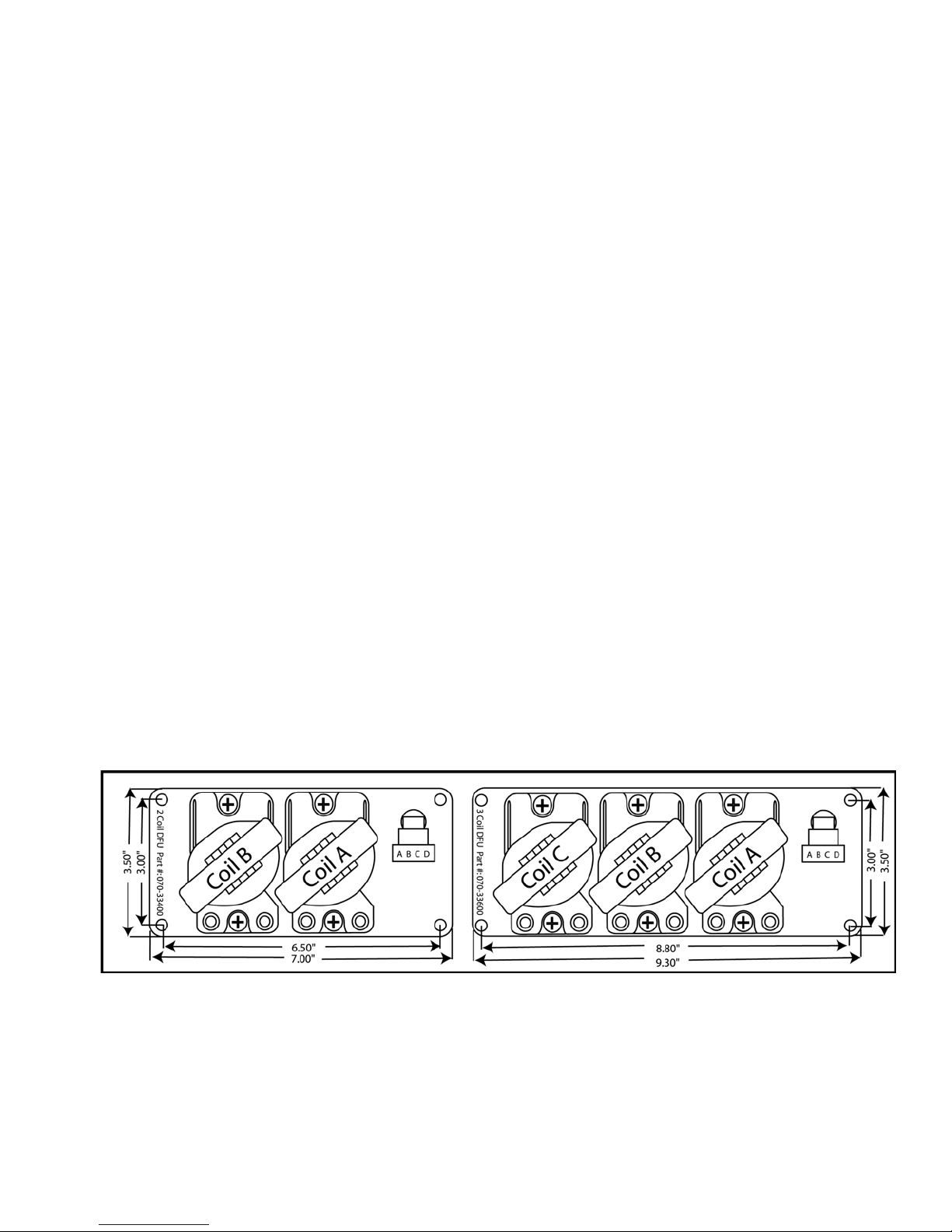
Fire Units (DFU’s) with twin-tower coils are available from Electromotive in 2- and 3-coil versions. Single
tower coils are available as well. These DFU’s are completely weather proof, and feature sealed electrical
connectors. Additionally, the DFU’s are impedance matched for optimum performance with our TECgt.
The TECgt with six dedicated fuel channels and drivers also covers fuel control. This allows up to
12 low or high impedance injectors to be driven. Staged injector firing is a built-in option on the TECgt
for most engine configurations. Sequential operation is also available through the use of a cam position
sensor but sequential operation is not available for the 8 cylinder engine option on the TECgt.
There are Nine dedicated, user-definable, general-purpose inputs / outputs (GP I/O’s) included with
the TECgt to make your high-tech engine setup a snap. The GP I/O’s can be used to control anything from
wastegates for turbo setups to simple electric radiator or intercooler fans. The possibilities are nearly
limitless.
One of the GPI’s has a frequency-based input capability, which can process data from wheel a
speed sensor or similar device. The other GPI’s are analog inputs only, and do not feature frequency-based
capabilities. These channels can perform fuel trims, timing trims, and many other functions.
Besides the GP I/O’s, several functions are built-in to the TECgt that are quite useful on most
applications. The following outputs are standard on the TECgt:
Tachometer (configurable to drive most modern tachs)
Check Engine Light
Fuel Pump Relay Ground (activated at appropriate times by the TECgt)
Idle Speed Motor control (stepper motor style or 2-wire style)
The TECgt uses the following inputs to perform engine management:
Crank Trigger
Cam Trigger (optional)
Manifold Air Pressure
Coolant Temperature Sensor
Manifold Air Temperature Sensor
Throttle Position Sensor
Knock Sensor (optional)
Exhaust Gas Oxygen Sensor (O
sensor)
2
______________________________________________________________________________________
TECgt Manual Version 2.0 - Page 8 - ©2008 Electromotive, Inc.

A. Installing the TECgt System
A.1. How it All Works: The Two Pages You Need to Read
The goal behind Electromotive’s Total Engine Control product line is to provide complete, highresolution control of all functions of the modern engine, and to do so with a user-friendly interface.
Consequently, the TECgt is designed to easily control a huge number of complex engine management
functions through the hands of a user who is new at the game.
Engine Speed & Position = Crank Sensor…
What separates our engine management systems from those of our competitors is the fact that our
products are all designed around an ultra high-resolution ignition. For this reason, we use a 60(-2) tooth
crank trigger wheel to give the computer an extremely accurate engine position input. This is also the
reason that we do not support any other types of trigger inputs. Take, for instance, the flying magnet
trigger input used by some manufacturers: 8 cylinder engines have 4 magnets mounted to the crank trigger
wheel. Our 60(-2) tooth trigger has 15 TIMES MORE RESOLUTION! From a magnetic sensor aimed at
the trigger wheel, the TECgt receives its input for engine speed and position.
Engine Load = MAP Sensor…
As nice as the 60(-2) tooth trigger wheel is for determining engine speed and position, more is
necessary to perform ignition and fuel control; namely a load input. While many OEM’s use Mass Airflow
(MAF) sensors to determine the airflow (and thus the load) of an engine, Electromotive systems are
designed around Manifold Air Pressure (MAP) sensors as the load-determining device. MAP sensors
simply plug into the intake manifold of the engine (after the throttle), and are inherently easier to install
than MAF sensors since they are not sensitive to vacuum leaks or engine airflow requirements. A 1-Bar
MAP sensor is designed for naturally aspirated engines. A 2-Bar sensor is used for turbo/supercharged
engines with up to 15psi (about 200kPa absolute) manifold boost. A 3-Bar sensor is good for up to 30psi
(300kPa), while a 4-Bar is good for up to 45psi (400kPa). Choose the appropriate sensor for the
application, and you are done.
Ignition Advance Control…
Once the MAP sensor and crank sensor are installed, the TECgt has inputs for RPM and load.
Under steady-state conditions on a fully warmed-up engine, these are the only necessary inputs for the
TECgt to control the fuel and ignition curves. Control of the ignition advance curve is quite simple: there
is a table of RPM vs. MAP in which the desired ignition advance angle is entered for every point. The
table can be made in any size from 8
interpolation occurring. This keeps the advance curve from “stepping” from point-to-point. Additionally,
it means that the engine can be tuned with only a few input numbers; some other systems on the market
rely on the tedious input of hundreds of numbers to obtain an ignition advance curve that is still not as
smooth between data points as ours.
Fuel Injector Control…
Control of the fuel curve is very simple as well. When the user first sets up a calibration, the
Tuning Wizard is generally used. The Wizard asks for the engine horsepower, peak RPM, number of
injectors, and the amount of manifold boost. From these, a raw fuel curve is established. Most
importantly, the User Adjustable Pulse Width (UAP/TOG) is established. UAP/TOG is the fuel injector
pulse width when the MAP sensor reading is full-scale (wide-open throttle on a 1-Bar MAP sensor, 15psi
boost on a 2-Bar sensor, etc.). The second variable that is established is the Injector Offset Time (IOT).
IOT and TOG can be thought of as the idle adjustment screw and the main power jet of a carburetor,
x8 to 16x16 data points. Between each data point, there is a 256 point
______________________________________________________________________________________
TECgt Manual Version 2.0 - Page 9 - ©2008 Electromotive, Inc.

respectively. From these two numbers, a fundamental fuel curve is established. However, the
fundamental fuel curve only works on a thermodynamically linear engine. A thermodynamically linear
engine would have a torque curve that is a flat horizontal line from idle to redline. In reality, engines stray
from this straight line, sometimes dramatically, as in the case of motorcycle engines. To compensate for
non-linear fuel consumptions, a Volumetric Efficiency (VE) table is included in the software. The VE
table is based on RPM and MAP readings (like the Advance Table) to provide fuel injector pulse width
offsets for various loads and engine speeds that stray from linear.
Compensations…
Having a warmed-up engine running under steady-state conditions is all well and good, but in the
real world, we must deal with cold weather starting, engine accelerations and decelerations, etc. For these
scenarios, engines need fuel and spark compensations. The coolant temperature sensor (CLT) provides an
input for the TECgt to measure the engine temperature. Since cold engines need more fuel than hot
engines, tables are provided in the software to allow fuel flow increases as a function of engine
temperature. Other parameters related to the coolant temperature are cold starting (cranking) enrichments
and throttle movement enrichments when cold. A Manifold air temperature (MAT) sensor is mounted in
the intake tract to measure incoming air temperature. This reading is used to supply additional fuel for cold
weather, or to take away some fuel on hot days. The throttle position sensor (TPS) is used for functions
similar to the accelerator pump on a carburetor. Also, the TPS reading is used in the TPS-MAP Blend
routine, which is very useful for multiple throttle setups and radically-cammed engines.
Additional Features…
Once all the necessary input sensors are in place, and the software is tuned, the engine will run quite
well. However, to further refine the control of the engine, a few additional features are included. The idle
air control motor (IAC) is used to meter air into the engine at idle. This helps maintain a smooth idle,
regardless of operating conditions. It can also be used to increase the idle for cold temperatures, or air
conditioner activation. A fuel pump output is also included, which allows the user to turn on the fuel pump
relay for a set amount of time when the ignition is turned on. This primes the fuel system, and powers the
fuel pump once the engine is cranked and running. A tachometer output is included, which will drive most
modern tachometers, and a check engine output is included to keep track of failed engine sensors. A host
of other engine input and output options are included as well, and are outlined in other areas of this manual.
A.2. Pre-Installation Checklist
To perform a complete TECgt installation, the following items are required:
1. TECgt Computer
2. DFU(s)
3. Resistor Core Spark Plug Wires (see notes on Spark Plug Wires)
4. TECgt Wiring Harness w/ Power Harness
5. Windows-based PC-type Computer (see notes on Computer Requirements)
6. Serial Connector Cable (DB9) for PC
7. Crank Position Sensor (Magnetic Sensor)
8. 60 (-2) Tooth Crank Trigger Wheel or 120 (-4) Tooth Cam Trigger Wheel
9. Coolant Temperature Sensor (CLT)
10. Manifold Air Temperature Sensor (MAT)
11. Manifold Air Pressure Sensor (MAP)
12. Throttle Position Sensor (TPS)
13. Exhaust Gas Oxygen Sensor (EGO)
14. Idle Air Control Motor (IAC)
15. Knock Sensor (KNK)
______________________________________________________________________________________
TECgt Manual Version 2.0 - Page 10 - ©2008 Electromotive, Inc.
16. Fuel Rail(s) and Fuel Pressure Regulator (see notes on Fuel Pressure Regulator)
17. High Pressure Electric Fuel Pump (see notes on Fuel Pump)
18. Fuel Injectors (see notes on Fuel Injectors)
19. Fuel Injector Wiring Harness
20. Throttle
21. Wire Terminal Crimping Tool (available from Electromotive)
22. Shrink Tubing
23. Assorted Wire Crimp Terminals
24. Drill
25. ¼” Bolts for DFU(s) & TECgt ECU
26. Soldering Gun
A.3. Mounting the Main Computer and DFU
For utmost reliability, install the TECgt computer where temperatures will not exceed 150
o
(65
C). It is recommended that the TECgt computer be installed in the passenger compartment of the
vehicle where it will not be exposed to the elements. A good location is in the kick panel of a vehicle
originally equipped with a factory ECU. If the TECgt must be mounted in an area that is partially exposed
to the elements, there should not be a problem; the circuit board is completely sealed for harsh environment
installations. A well vented area is recommended, particularly in engines utilizing most of the injector
channels and operating at sustained high speeds. It should be noted that the TECgt might get hot under
prolonged high-rpm operation. As long as air is moving around the ECU, there is no risk of damage to the
TECgt; just be careful not to burn yourself on the unit! Secure the TECgt ECU with four ¼” socket head
cap screws. The wiring harness should be passed through the firewall using a suitable grommet to avoid
chafing.
The DFU(s) can be placed nearly anywhere under the hood of the vehicle where the temperatures
are below 250
o
F (120oC). Since they are entirely sealed, exposure to the elements is not an issue. The
DFU Ground Wire MUST be installed to vehicle ground.
It is recommended that the ECU and DFU be separated by at least six inches for the purpose of
reducing electrical noise in the ECU.
o
F
2-Coil DFU Dimensions 3-Coil DFU Dimensions
______________________________________________________________________________________
TECgt Manual Version 2.0 - Page 11 - ©2008 Electromotive, Inc.
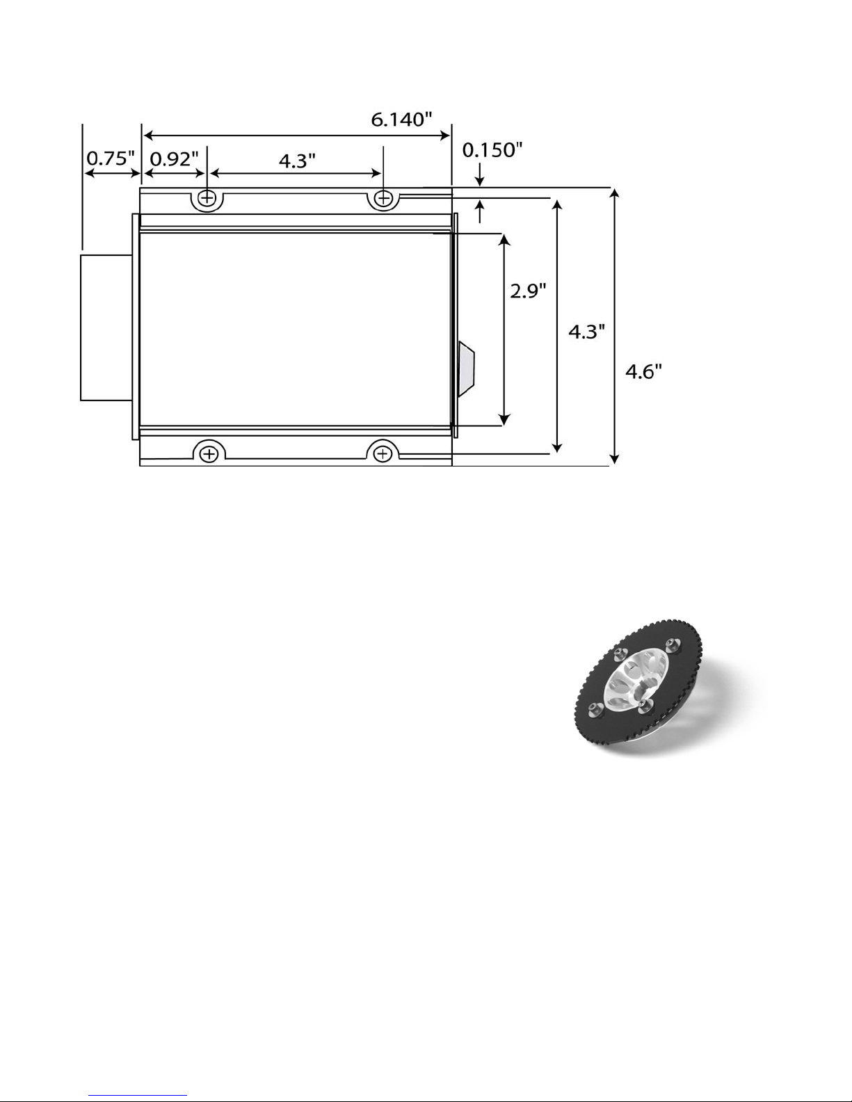
TECgt ECU Dimensions (bolt pattern is 4.3” x 4.3”)
A.4. Trigger Wheel and Sensor Installation
The foundation of the TECgt ultra-high resolution ignition is
the 60(-2) tooth trigger wheel. The trigger wheel is designed to give
uncompromising timing accuracy at the highest engine acceleration
rates. As such, Electromotive does not support other triggering
systems, particularly those of the “flying magnet” variety. These
systems can lead to vastly inaccurate spark timing, and can contribute
to engine damage. For most applications, the 60(-2) tooth trigger
wheel is mounted on the crankshaft damper or pulley. Some
applications may warrant the use of a camshaft- or distributor-mounted trigger wheel. With this setup, a
120(-4) tooth trigger wheel is necessary, since the camshaft turns at half the speed of the crank.
A.4.a. Crankshaft Trigger Installation for 60(-2) Tooth Wheel
For a crankshaft-mounted trigger wheel setup, an appropriate place must be found to mount the
wheel and trigger. Typically, the easiest place to mount a trigger wheel is on the harmonic damper or
pulley. If it is mounted on a damper, it should be mounted on the inner hub rather than the outer
dampening ring. The damper/pulley should be keyed to the crankshaft so that it cannot spin on the
crankshaft, as this would cause an ignition timing error. When using a damper that has bolt-on pulleys, the
trigger wheel can usually be mounted between the pulleys and the damper. However, the accessory pulleys
will need to be shimmed out by 1/8” (the thickness of the trigger wheel). A variety of application-specific
trigger wheels are available. See Appendix II for a listing of applications. Universal trigger wheels are
______________________________________________________________________________________
TECgt Manual Version 2.0 - Page 12 - ©2008 Electromotive, Inc.
also available in a variety of sizes, and are listed in Appendix II as well. Electromotive can custom-make
trigger wheels in nearly any configuration for a one-time tooling fee.
To choose the proper size trigger wheel, find the diameter of the pulley or damper on which the
wheel is to be mounted. The trigger wheel diameter should be about ½” larger than this diameter. It should
also be noted that the trigger wheel should be at least ¼” from any moving magnetic pieces, such as bolts
or other fasteners, to avoid interference and false triggering. It is important that the trigger wheel be
perfectly concentric with the crankshaft centerline. To achieve concentricity, a shallow cut can be
machined in the front or rear face of the damper to create a centering ledge, and a hole can be created in the
trigger wheel to match the ledge diameter. The trigger wheel can then be drilled to bolt it to the damper.
See Table A.4.1 below to determine the tolerances that must be maintained when mounting the
trigger wheel. These tolerances may require the use of a lathe to true the trigger wheel with the crankshaft
centerline, which can be accomplished by putting the entire damper/trigger wheel assembly on the lathe.
Note that the maximum out-of-round is the distance between the lowest and highest teeth and the crank
sensor. That is, if a feeler gauge is used between the sensor and the wheel to measure the out-of-round, the
reading between the lowest and highest teeth should not exceed the guidelines in the table.
Table A.4. 1: Crank Trigger Specifications
Trigger
Wheel
Size
2.5" 0.025" max 0.002"
3.5" 0.035" max 0.003"
5" 0.050" max 0.005"
6" 0.060" max 0.006"
7.25" 0.070” max 0.007"
8.25" 0.080” max 0.008"
Air Gap
Maximum
Out-of-
Round
A.4.b. Magnetic Crank Sensor Installation
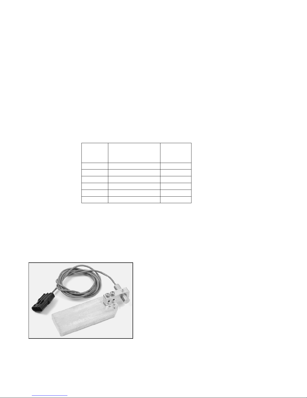
When installing the magnetic sensor, an appropriate bracket must be made to aim the sensor at the
trigger wheel. A good starting point for a magnetic sensor bracket is Electromotive part number 21072003, which is our universal sensor bracket (See Figure A.4. 1). If this part is not used as a starting point,
a custom bracket can easily be made. The most important things to remember when fabricating a
bracket are that it should be bolted directly to the engine block, away from rotating steel or magnetic
pieces, and should be nonferrous (not attracted to magnets). This will keep the sensor and trigger
wheel vibrating together so the gap between the two always
stays the same. Variations in sensor gap may cause erratic
timing or false triggering of the ignition. (This is the reason
for not mounting the trigger wheel to the outer ring of a
harmonic damper.) As such, any custom magnetic sensor
bracket should be very rigid. The sensor can be secured with
either a set screw or a clamping arrangement, as long as the
1/2” sensor is utilized (part number 250-72218). If the smaller
3/8” sensor is utilized, a clamping arrangement should be
employed rather than a setscrew, as the setscrews may crush
the sensor. See Table A.4. 2 for the appropriate magnetic
Fig A.4. 1: Universal Crank
Sensor Bracket
______________________________________________________________________________________
TECgt Manual Version 2.0 - Page 13 - ©2008 Electromotive, Inc.
sensor/trigger wheel combinations.
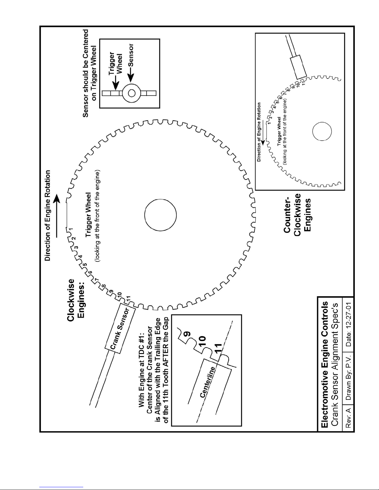
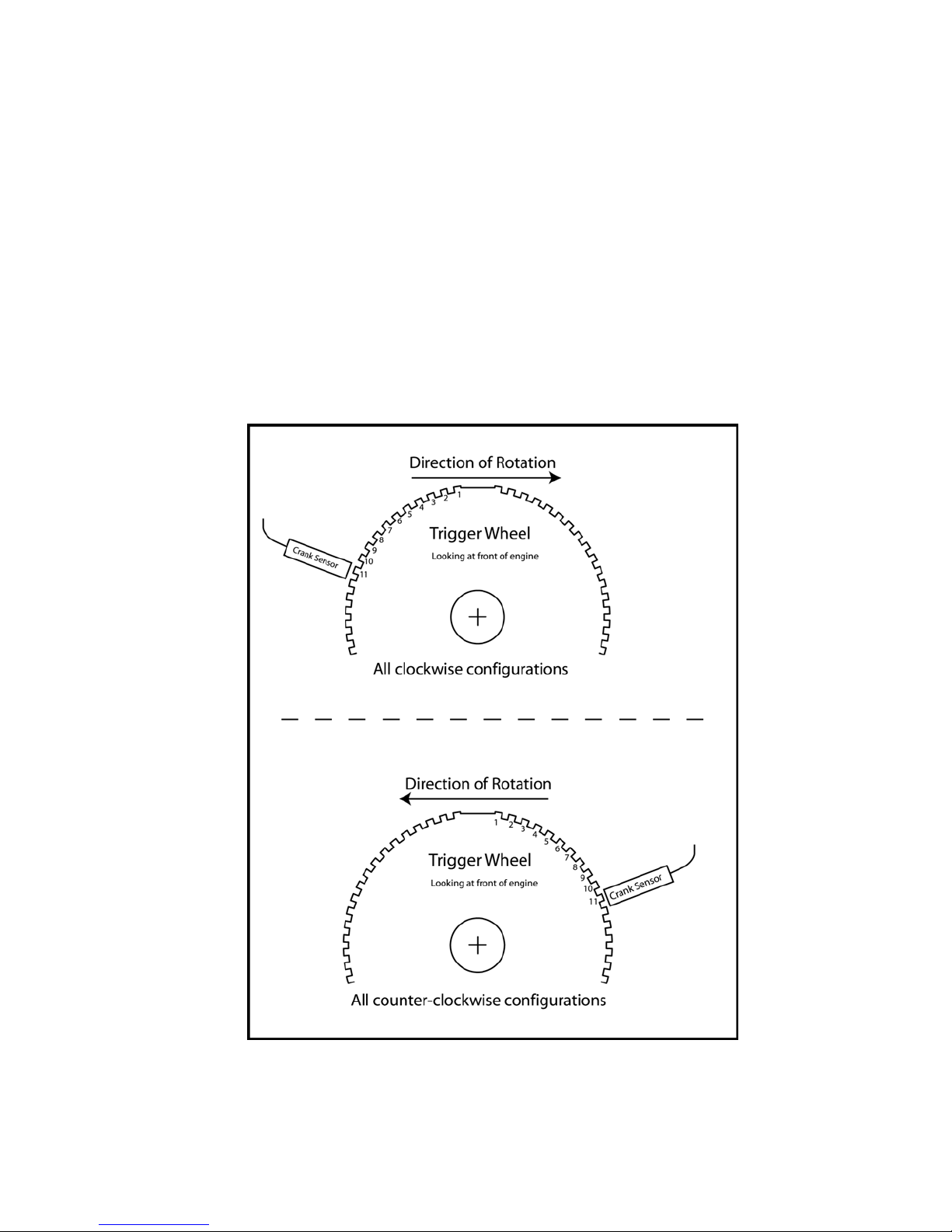
Once a magnetic sensor and trigger wheel are installed, they must be aligned such that the TECgt
computer knows where to locate Top Dead Center of the #1 cylinder (referred to as TDC #1). Correct
alignment necessitates that the center of the sensor must be aligned with the trailing edge of the 11th
tooth after the two missing teeth when the engine is at TDC #1 (see the drawing at the end of this
section). Aligning the magnetic sensor with anything other than the 11
th
tooth will cause an ignition timing
retard or advance, depending on the direction of the misalignment. Each tooth represents six degrees, so if
the sensor is aligned with the trailing edge of the 12
Conversely, if the sensor is aligned with the trailing edge of the 10
th
tooth, the timing will be advanced by six degrees.
th
tooth, the timing will be retarded by
six degrees. In the event that the sensor is not aligned correctly, the WinTec software can be made to
compensate by manipulating the Tooth Offset Parameter, as outlined in Section A.4.g of this manual.
IMPORTANT NOTE :
Make sure that the Mag. Sensor harness is NOT routed near battery cables or other high
current leads or devices such as cooling fans, starter or alternator. Coil wires, injector leads also
should be avoided.
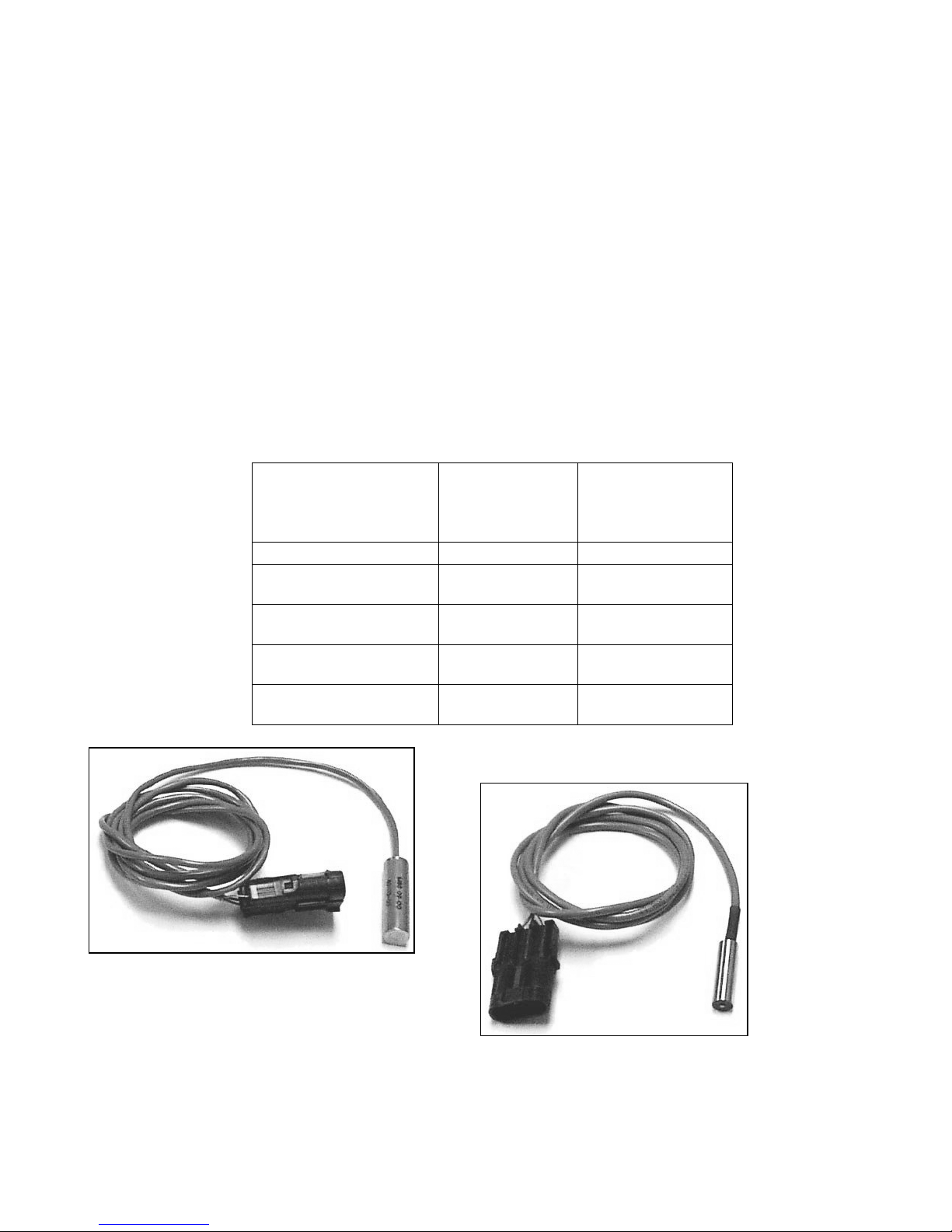
Table A.4. 2: Magnetic crank sensor selection. Note: use a clamping arrangement for securing 3/8”
sensors, rather than a setscrew. The ½” sensors can be secured with any clamping method.
All 120 (-4) Tooth
2-3/8” & 2-1/2”
60 (-2) Tooth
3-1/2” 60 (-2) Tooth
(below 6000rpm)
3-1/2” 60 (-2) Tooth
(Above 6000rpm)
Greater than 3-1/2”
60 (-2) Tooth wheels
3/8” Diameter
Chisel Point
Sensor
PN: 250-72212
X
X
X
X
X
1/2” Diameter
Flat Tip
Sensor
PN: 255-72218
X
X
X
Fig A.4. 2: Electromotive ½” (12.7mm)
crank sensor
”
______________________________________________________________________________________
TECgt Manual Version 2.0 - Page 14 - ©2008 Electromotive, Inc.
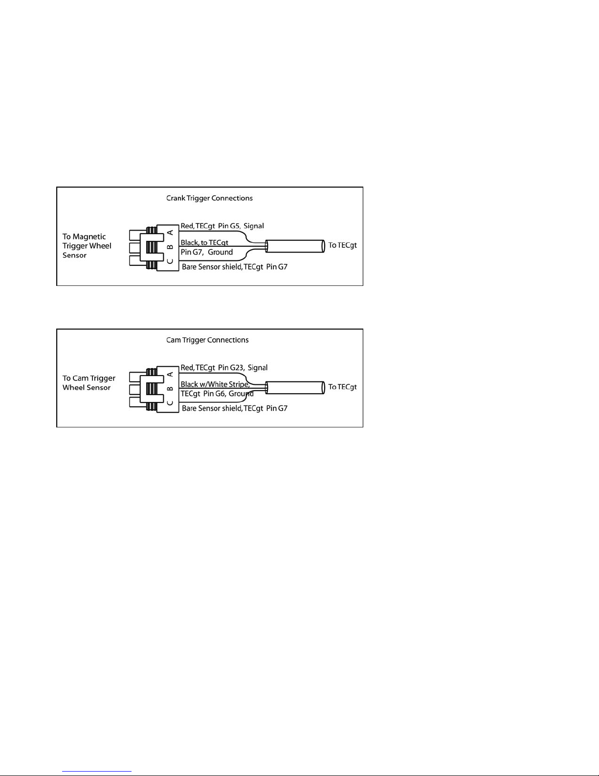
A.4.c. Wiring the Magnetic Sensor
The crank sensor has three wires. The red wire is the signal from the sensor, the black wire is the
signal ground, and the bare wire is the shield. The harness has provisions for both a crank and a cam
sensor. The crank sensor cable must be used for all 60 (-2) or 120 (-4) tooth trigger wheel inputs. The
cam sensor cable should only be used for the “sync” pulse from the cam-mounted trigger wheel on
sequential applications. If you are unsure which cable is for the crank sensor, measure the resistance
between pin G5 on the TECgt harness and the red wire coming out of both the crank and cam cables. The
wire that reads zero resistance to pin G5 is the crank sensor wire. See Figure A.4. 4 for details. Consult
the end of this section for details on sequential applications.
Figure A.4. 4: Wiring layout for crank G5 and cam G23 sensors. Note that the Cam Sensor is only used
on full sequential applications. It is NOT used on applications using the 120(-4) tooth cam trigger wheel
with no crank trigger.
A.4.d. Verifying Trigger Wheel Timing
The most important step in the trigger wheel installation process is to check the ignition advance
with a timing light. A timing indicator (pointer) should be attached to the engine block, and it should point
at a line on the crankshaft pulley or trigger wheel when the engine is at TDC #1. When running the engine,
verify that the timing value read by the timing light corresponds to the timing value in the software’s
engine monitor screen.
Use of a good-quality inductive timing light is recommended. DO NOT use a timing light that goes
between the spark plug and spark plug wire with a clamp probe. Dial-Back inductive timing lights can be
used, but will need to be dialed to DOUBLE the actual desired timing value due to the waste-spark firing of
the DFU coils. They are fooled into thinking that the timing is twice as advanced as it actually is.
______________________________________________________________________________________
TECgt Manual Version 2.0 - Page 15 - ©2008 Electromotive, Inc.
______________________________________________________________________________________
TECgt Manual Version 2.0 - Page 16 - ©2008 Electromotive, Inc.

A.4.e. Camshaft- & Distributor-Mounted Trigger Setups
While crankshaft mounted triggers are preferred, it is sometimes easier to install a camshaft- or
distributor-mounted trigger wheel. For these cases in which the trigger wheel is spinning at half the
engine speed, a 120(-4) tooth trigger wheel is necessary. This wheel has two sets of two missing teeth,
spaced 180 degrees apart. As such, the input to the TECgt is identical to that of the crank-mounted 60(-2)
tooth trigger wheel. Electromotive offers 120 (-4) tooth wheels in 3.25” and 2.75” diameters.
It is often easy to use an old distributor rotor to serve as the mount for a 120(-4) tooth trigger wheel.
A simple nonferrous bracket would need to be fabricated to hold the sensor. The 3/8” chisel point sensor
(PN: 250-72219) must be used on 120(-4) trigger wheels. As such, the bracket for the sensor should use a
clamping arrangement rather than a setscrew to hold the magnetic sensor. Just like the crank-mounted
trigger, the distributor/cam-mounted triggers require the sensor to be aligned with the trailing edge
of the 11
th
tooth after the two missing teeth when the engine is at TDC #1. The same tolerances that
apply to the crankshaft-mounted trigger wheels (Table A.4. 1) apply to the camshaft-mounted trigger
wheels as well.
A Note on Engines with High-Overlap Camshafts:
If your engine is equipped with a camshaft that has early intake valve openings or very long
duration, you may experience backfiring through the throttle during starting. This is caused by the intake
valves beginning to open on the exhaust stroke. Since the spark plugs fire on both the compression and the
exhaust strokes, the spark on the exhaust stroke may cause unburned fuel in the intake manifold to ignite,
resulting in a backfire.
To remedy this situation, advance the “mechanical” timing by manipulating the DFU “A” Trigger
Wheel TDC Parameter. If your crank sensor is aligned with the 11
th
tooth of the trigger wheel at TDC #1,
setting the Tooth Offset to a number LOWER than 11 will add mechanical advance. If the number “10”
was set for the Tooth Offset, the mechanical timing would be ADVANCED by 6 degrees (6 degrees per
tooth). This would require that you subtract 6 degrees from the values in your ignition advance table in
WinTec to obtain your desired advance value. That is, the timing table will have to read 30 degrees in
order for the engine to operate at 36 degrees advance. See Section A.4.g. for more details.
A.4.f. Full Sequential Applications – Cam Synchronization
When full sequential fuel operation is desired, a once-per-engine-cycle synchronization, or “sync,”
pulse must be received by the ECU. Typically, the sync pulse is generated by the installation of a 1-notch
(or 1-tooth) trigger wheel onto the camshaft. A standard Electromotive magnetic (inductive) sensor can
then be used to obtain the reading from this trigger wheel. A Hall effect sensor could also be used as a
triggering method instead of a magnetic sensor setup. With either method, the tooth must pass by the
magnetic sensor between 180
See Figure A.4. 7 for installation details.
The TECgt will only trigger off a rising edge during the synchronization period (between 180o
o
and 6
BTDC compression). A rising edge occurs when the metal on the cam trigger wheel becomes
closer to the sensor over a very short period of time. See Figures A.4. 6 and 7 for representative examples
and different cam trigger wheel designs, and their rising edge location.
o
and 6o before TDC Compression (not exhaust) of the number one cylinder.
______________________________________________________________________________________
TECgt Manual Version 2.0 - Page 17 - ©2008 Electromotive, Inc.
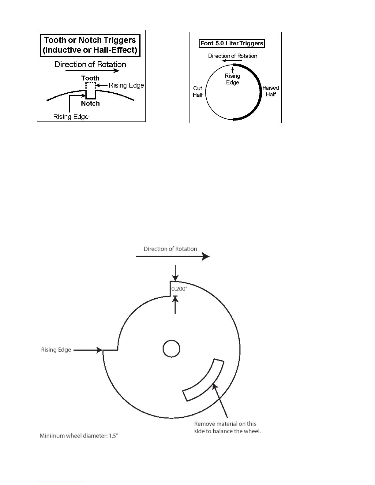
Figure A.4. 6: Tooth/Notch Triggers Figure A.4. 7: Ford “Half-Moon” Trigger
Most types of sensors are compatible with the TECgt’s sync pulse requirement. This would
include most Hall effect, flying magnet, and reluctor sensors. As long as the sensor outputs a rising voltage
to the TECgt between 180
o
and 6o before TDC compression for the number one cylinder, it should work
perfectly.
Terminal G23 on the ECU is used for cam sync inputs (as shown in Figure A.4. 4). If using a Hall
effect or other sensor type that is powered by +5Volts, be sure that the output signal from the sensor is
going into terminal G23. If using a magnetic sensor with a custom steel trigger wheel, we recommend
using our magnetic sensors. The red wire from the sensor should go to terminal G23. Keep in mind that
when adapting an OEM cam trigger setup to a TECgt, the wheel may need to be rotated to place the rising
edge in the appropriate degree window for the TECgt.
Figure A.4. 8:
Proper cam
trigger
installation. This
cam trigger
occurs approx.
o
90
BTDC
Compression on
the #1 cylinder
(as measured at
the crank). Note
the 87 degree
(as measured on
the cam wheel)
“window” in
which the rising
edge must occur.
______________________________________________________________________________________
TECgt Manual Version 2.0 - Page 18 - ©2008 Electromotive, Inc.

A.4.g. TDC Tooth Setup Software Adjustment Parameters
So, you took a lot of time to install your trigger wheel, and now you realize that you didn’t get the
trailing edge of the 11
th
tooth to align with the center of the magnetic sensor with the engine at TDC #1.
What to do?
The WinTec software features a TDC setup parameter that allows users to manipulate the TDC
point for the trigger wheel. There are two adjustable parameters:
Change DFU “A” Trigger Wheel TDC
Change DFU “B” Trigger Wheel TDC
For all but the odd-fire applications, the adjustment is only present for the DFU “A” TDC. The
default setting for DFU “A” TDC is 11, signifying TDC alignments with the 11
with the 13
th
tooth at TDC, change this number to 13. Several late-model Bosch-equipped applications use
th
tooth. If you are aligned
our 60 (-2) tooth trigger wheel, but come from the factory with a different TDC tooth alignment. Typically,
these setups are referenced to the 14
th
tooth for TDC, but you MUST confirm this on your application,
since Bosch used a few different offsets through the years.
Odd-Fire applications have the ability to move the TDC reference for the second DFU (using the
parameter “DFU “B” Trigger Wheel TDC”). This allows the user to define the odd-fire ignition split that is
present on the engine. Refer to Section C.5 to determine the proper settings for this value.
Some applications may require more “mechanical timing” to compensate for large, high-overlap
cams. Assuming the crank sensor is aligned with the 11
th
tooth at TDC, this can be done by entering a
value for the “Change DFU “A” Trigger Wheel TDC” that is LESS than 11. Each tooth less than 11
represents 6 degrees of advance that is added to the Ignition Advance Table.
Some applications may require less “mechanical timing” (some rotary users may wish to do this).
Assuming the crank sensor is aligned with the 11
th
tooth at TDC, this can be done by entering a value for
the “Change DFU “A” Trigger Wheel TDC” that is MORE than 11. Each tooth more that 11 represents 6
degrees of retard that is subtracted from the Ignition Advance Table.
If an odd-fire engine has the trigger wheel installed incorrectly, and the DFU “A” TDC parameter is
changed to compensate for the error, the “DFU “B” Trigger Wheel TDC” parameter needs to be
manipulated in the same amount. As an example, if the TDC for DFU “A” is at 11 and is moved to 10, the
TDC for DFU “B” would need to be moved from 16 to 15.
The following pages outline the various situations that can be addressed through the TDC software
parameters.
Situation A
Problem:
Incorrect trigger wheel alignment results in undesired mechanical timing.
Solution:
With the engine at TDC #1, find the trigger wheel tooth that is aligned with the crank sensor. Enter the
number of this tooth into the TDC Tooth Alignment Parameter. The timing will be shifted to make the
Ignition Advance Table accurate.
Method:
The software will automatically RETARD the timing when a number GREATER THAN 11 is entered into
the TDC Tooth Alignment Parameter. The timing will be automatically ADVANCED when a number
LESS THAN 11 is entered.
Situation B
Problem:
The engine needs less mechanical advance, and the crank sensor is aligned with the 11
th
tooth.
______________________________________________________________________________________
TECgt Manual Version 2.0 - Page 19 - ©2008 Electromotive, Inc.
Solution:
Enter in the number “12” to the TDC Tooth Alignment Parameter. The timing values will be automatically
RETARDED by 6 degrees. The Ignition Advance Table values will now be incorrect (the displayed values
will be 6 degrees higher than the actual advance).
Situation C
Problem:
The engine needs more mechanical advance, and the crank sensor is aligned with the 12th tooth instead of
th
the 11
Solution:
Enter in the number “11” to the TDC Tooth Alignment Parameter. The timing values will be automatically
ADVANCED by 6 degrees. The Ignition Advance Table values will now be incorrect (the displayed
values will be 6 degrees lower than the actual advance).
Note:
In the past, aligning the sensor with the 12th tooth would advance the mechanical timing by 6 degrees.
.
Figure A.4. 9 - TDC tooth for two possible scenarios.
______________________________________________________________________________________
TECgt Manual Version 2.0 - Page 20 - ©2008 Electromotive, Inc.

In a normal scenario, not considering software manipulation, aligning the magnetic sensor with
anything other than the 11
direction of the misalignment. Each tooth represents six degrees, so if the sensor is aligned with the trailing
edge of the 12
the trailing edge of the 10
required for easier starting (high compression/radical cam timing engines, for example), aligning the sensor
with the 12th or 13th tooth will yield 6° or 12° (respectively) of advance during cranking. Also check that
the sensor is centered over the edge of the wheel.
th
tooth, the timing will be advanced by six degrees. Conversely, if the sensor is aligned with
th
tooth will cause an ignition timing retard or advance, depending on the
th
tooth, the timing will be retarded by six degrees. If some ignition advance is
A.5. Wiring the TECgt
Introduction
The task of installing a TECgt wiring harness may seem a bit intimidating at first. However, by
dividing the wiring installation into a few small jobs, it can be accomplished by most installers in a
reasonable amount of time.
WARNING: Always disconnect the battery when doing ANY electrical work on a
vehicle. Use common sense when working around electrical systems, particularly the
TECgt DFU coils. The voltage output of the coils can be well over 40,000 Volts at a
given instant.
A.5.a. TECgt - Main Power Connections
The two wires (with their own connector) that protrude from the TECgt ECU are the main ground
and switched ignition power. The ground wire is 10awg. The reason for the larger/thicker size of the wire
is that the ECU is mainly in charge of switching the GROUNDS, not the +12 Volt power. As an example,
the fuel injector and coil outputs are all pull-to-grounds. The +12 Volt power is supplied on a harness that
is external to the TECgt.
The red 12awg wire in position (A) on the 2-position connector should be connected to Switched
+12 Volt Input. This wire is used to turn the unit on and off as well as supply power to the ECU. As such
it only flows a very small amount of current (less than 1 amp). This wire can be placed on the ignition
switch circuit. The black 10awg wire in position (B) of the connector should be connected to full time
battery negative. The TECgt is shipped with the corresponding connector with five feet of wire. See
Figure A.5. 1 for a wiring diagram.
If you are using the TECgt Power Harness, refer to the next section on installing the Switched +12
Volt Input into the Power Harness.
A.5.b. Power Harness Installation
Electromotive’s Power Harness (PN 070-40000) for the TECgt is capable of supplying the +12Volt
high-amperage power required to run the DFU’s, injectors, EGO sensor heater and fuel pump. Included in
the harness is a fuse block with four fuses (ignition, DFU’s, Injectors and Fuel Pump are fused) and two
relays to switch the power. Our custom harnesses are all built with the power harness pre-installed, so
wiring them is even more straightforward. Figure A.5. 1 gives an example of a typical Power Harness
installation.
______________________________________________________________________________________
TECgt Manual Version 2.0 - Page 21 - ©2008 Electromotive, Inc.

There are three breakouts in the Power Harness:
• TECgt Connections
• Power Inputs
• Power Outputs (w/ switched voltage input)
• TECgt Connections
The TECgt Connections are color-matched to the TECgt harness.
Light Green 20awg Wire: Connects to Pin G17 (Fuel Pump Relay Ground)
Yellow (from power harness) 20awg Wire: Connects to 2 wire (separate connector- Pin A, red wire
10awg) = Switched +12v input
• Power Inputs
The Power Inputs are color coded in standard fashion:
Red 12awg Wire: Connect to (Switched +12V input)
Black 10awg Wire: Connect to Vehicle Ground
• Power Outputs (w/ switched voltage input)
The power outputs provide power for the DFU’s, injectors, EGO sensor heater, and Fuel Pump. The
switched voltage input is used to turn on the TECgt ECU, and should be wired to a +12Volt source that is
activated with the ignition key.
Purple/White Stripe 16awg: Injector Power (runs to all injectors)
Red/White Stripe: DFU Power (pin “D” on DFU’s)
Green 16awg: Fuel Pump Positive and EGO Sensor Heater Positive
Yellow 18awg: Switched +12 Volt Input (for TECgt turn-on request)
The Wiring Diagrams in the DFU and Injector wiring sections of this manual show the terminals on which
the power should be brought in. Any reference to fusing the power source in these sections is unnecessary
when using the Power Harness, since the connections are already fused.
______________________________________________________________________________________
TECgt Manual Version 2.0 - Page 22 - ©2008 Electromotive, Inc.
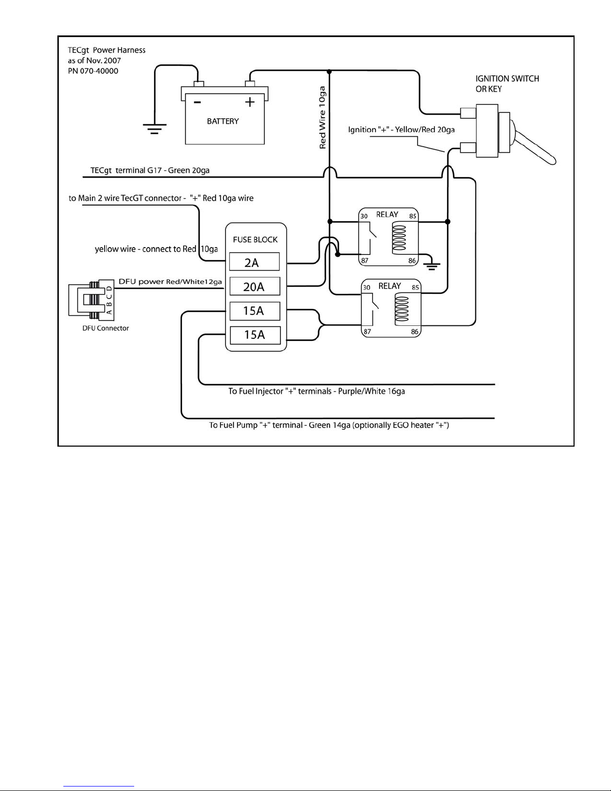
Figure A.5.1: TECgt Power Harness (PN: 070-40000).
A.5.c. Wiring the Fuel Injectors
The Injector connectors use pull-to-seat terminals. DO NOT crimp the terminals onto the wires until
you have fed the wires through the connector!
When wiring the injectors, Section D must be referenced to determine the correct wiring for your
application. To summarize the main wiring points from Section D:
• Injector drivers 1-4 use a Yellow base color. The stripe color indicates the channel (Black-RedGreen-Blue = Channel 1-2-3-4).
• Injector drivers 5-6 use a Light Blue base color. The stripe color indicates the channel (Black-Red
= Channel 1-2).
• All injectors need a +12Volt connection on one terminal and a TECgt Injector Output on the other
terminal.
______________________________________________________________________________________
TECgt Manual Version 2.0 - Page 23 - ©2008 Electromotive, Inc.

• Low Impedance injectors should be wired in pairs (in parallel), and should not be used on a oneper-driver basis.
• High Impedance injectors can be used with either 1 or 2 per channel. When using two per channel,
wire them in parallel.
When using the Power Harness, refer to Figure A.5. 1 to obtain the fused +12Volt source for the
fuel injectors. It is the Purple w/ White stripe wire coming out of the Power Harness.
A.5.d. Wiring the DFU’s
The DFU connectors use pull-to-seat terminals. DO NOT crimp the terminals onto the wires until
you have fed the wires through the connector!
When wiring the DFU’s, Section C must be referenced to determine the correct wiring for your
application. To summarize the main wiring points from Section C:
• Terminal “D” on the DFU connector is the +12Volt connection.
• The TECgt harness has two cables for the DFUs. The first cable has three 16awg wires with a
shield. The second cable has two 16awg wires with a shield.
• The 3-wire DFU cable has the outputs for A, B, and C channels.
• The 2-wire DFU cable has the outputs for C and D channels. Channel C is in the second cable for
ease of wiring 8-cylinder and 2-rotor engines.
A.5.e. Wiring the Engine Sensors
The TECgt harness has provisions to connect all of the engine devices outlined in Sections G and F
of this manual. Refer to this section to wire your sensors appropriately.
• The following sensors use pull-to-seat connectors (feed the wire through the connector before crimping
the terminal!):
Coolant Temperature
Manifold Air Temperature
Some Throttle Position Sensors
Idle Air Control Motor
• The following sensors use push-to-seat connectors (crimp the terminal to the wire before inserting into
the connector!):
Crank Sensor
Cam Sensor (if used)
MAP sensor (1-Bar sensors use green connector. 2-& 3-Bar use orange connector)
Some Throttle Position Sensors
EGO Sensor
Knock Sensor
______________________________________________________________________________________
TECgt Manual Version 2.0 - Page 24 - ©2008 Electromotive, Inc.

• A brief word on Crimp Terminals…
When crimping terminals to the sensor wires, care must be taken to ensure that a proper crimp is
made. Improper crimps can lead to terminal failure and wire fatigue. To crimp properly, we recommend
using a high-quality ratcheting crimp tool (such a tool is available from Electromotive). In the absence of a
good crimp tool, the terminals can be soldered. Care should be taken to make absolutely certain that the
solder penetrates the terminal and gets to the wire.
There are two main crimp styles used with the TECgt sensors: Metri-Pack and Weather-Pack.
Metri-Pack terminals have two crimp areas. One area crimps to the bare (stripped) wire and provides the
electrical connection, and the other area crimps to the un-stripped wire housing to provide a strain relief.
Metri-Pack connectors are pull-to-seat.
Weather-Pack terminals also have two crimp areas, but instead of one area acting as a strain relief, it
is used to hold the connector seal in place. Therefore, when crimping a Weather-Pack terminal, always
insert the cable seal before crimping. Weather-pack connectors are push-to-seat.
Note : Soldered terminals will not tolerate much flexing. They may break if too much movement is
allowed.
B. Tuning Guide
Introduction
This section focuses on the tuning of a TECgt equipped engine. The tuning procedures outlined
here are based on an engine that has been wired correctly, has proper injector sizes, and has gone through
the Tuning Wizard with the engine parameters to establish a base program. Failure to meet any of these
criteria will make the tuning procedure difficult. Refer to section D.4 for terminology used in this section.
B.1. Adjusting the Timing Advance
Perhaps the most important step in tuning an engine is establishing the required ignition advance.
An engine with too much timing will detonate, regardless of how much fuel is thrown at it. An engine with
too little timing will perform poorly, and overheat the exhaust in short order. We are looking for the happy
medium here. Keep in mind that the timing settings are solely dependent on the crank trigger installation
angle. If the crank sensor is aligned with the 13
the engine timing will be mechanically advanced by two teeth (12 degrees). When this occurs, the timing
values in the Ignition Advance Table will be 12 degrees LESS THAN the actual engine timing. If the
crank sensor is aligned with the 10
th
tooth at TDC#1, the timing will be mechanically retarded by one tooth
(6 degrees). When this happens, the timing values in the Ignition Advance Table will be 6 degrees MORE
than the actual engine timing. Always confirm your timing values in the software with a timing light!
Remember that dial-type timing lights will not read correctly with the TECgt due to the waste-spark. See
Section A.4.d for more information on this topic. To avoid potential engine damage, it is best to check
engine timing with a timing light when first starting the tuning process.
As a guideline, most piston engines, regardless of compression ratio, will require anywhere from 820 degrees of advance when the engine is idling. Rotary engines require little or no timing at idle (some
even idle with negative advance!), so an ignition advance of zero may work best at low engine speeds.
Less timing makes the combustion process occur later, and thus makes the exhaust temperatures higher. It
also usually makes an engine idle somewhat rough. If your exhaust manifold is glowing red at idle, you
know one thing: there is not enough timing. NO
th
tooth of the trigger wheel when the engine is at TDC #1,
emissions will typically be low with too little timing.
x
______________________________________________________________________________________
TECgt Manual Version 2.0 - Page 25 - ©2008 Electromotive, Inc.

More timing makes the combustion process occur sooner, and will decrease exhaust temperature. It also
makes an engine idle smoother. NO
emissions will rise with too much timing.
x
With increasing RPM, the timing needs to be advanced for optimum power. This is a result of the
available time for combustion decreasing with increasing RPM. The peak cylinder pressure needs to occur
between 10 and 15 degrees after TDC compression for optimum power production, so the timing must be
tuned to allow this to happen. As a rule of thumb, engines with slow-burning (large) combustion chambers,
and/or low dynamic compression (low volumetric efficiency) typically need more timing advance, since the
flame front moves slowly. Engines with fast-burning (usually small) combustion chambers and/or high
dynamic compression ratios need less timing for optimum power, since the flame front moves faster.
Peak timing usually should occur by 3000 rpm on most engines. Load-dependent timing should
always be used, especially on turbo/supercharged engines. With increasing load (i.e. full-throttle or fullboost), less timing is needed. With decreasing load (i.e. cruising), increased timing is needed.
Rotary engines (particularly the turbocharged rotaries) do not give the tuner a margin of error when
it comes to ignition timing. They will detonate ONE TIME only, and will then be broken. The apex seals
cannot stand up to the huge shockwave generated by detonation. Tune these engines extremely
conservatively!! Start with the least amount of timing possible and the most amount of fuel possible. A
huge power-to-weight advantage is present on the rotary turbo engines, but it will only come to a tuner who
is cautious and patient.
B.2. Establishing Proper Starting Enrichments
When setting up the Starting Enrichments, it is generally best to first use the default settings from
WinTec. If these settings cannot start your engine, there would only be two possible causes: either the
enrichments are not adding enough fuel, or they are flooding the engine with too much fuel. Flooded
engines are easy to spot, since there will be a strong fuel odor in the air around the engine. Alternatively,
the spark plugs can be removed to check for flooding. Flooded spark plugs will be wet with fuel when they
are removed. If an engine is not flooded but still will not start, it is most likely not getting enough fuel.
For engines that will not start when cold, look to SE0 (the Temperature-Based One Second Starting
Enrichment). If the engine is flooding out during cold starting, decrease this number. If this number is
already zeroed out, and the engine is flooding, look to SE1 (the Constant One Second Starting Enrichment).
If SE1 is too high, the engine will flood out during cold AND hot cranking, since its value is added
regardless of temperature. If both of these values are set very low, and the engine still floods during
starting, look to PW0 (the Fixed One Second Starting Pulse Width). Most engines will not need PW0, so it
is generally best to set this to zero. ASE-0 and ASE-1 can also contribute to a flooding problem. If these
values are set too high, there may be too much fuel present at cranking.
An injector that is stuck open can sometimes cause a scenario that can be confused with engine
flooding on start-up. An injector that is stuck open will spray fuel into its respective cylinder as long as
there is fuel pressure. This will fill a cylinder with fuel in short order and effectively lock the engine. The
starter motor won’t be able to turn the engine over, since an engine cannot compress liquid fuel very easily.
Placing a screwdriver on the side of the injector and listening for a clicking sound is a good way to pinpoint
a stuck injector. If the injector is not clicking, it is not opening and closing.
For engines that are not getting enough fuel on start-up, the procedure for tuning the Starting
Enrichments is basically the opposite of that outlined above. On cold engines that are not getting enough
fuel, check the SE0 parameter. If this value is not high enough, a cold engine will not get enough fuel to
start. Coinciding with this, an engine will also need SE1 to be properly established for proper starting.
SE1 has an effect on both hot and cold engines, since it is not temperature-dependent. Some engines may
need PW1 to provide an additional amount of fuel pulse width, particularly on cold starts (temperatures
below CLT0). However, this value is typically not needed for multi-port injection applications.
An injector that is stuck in the closed position can cause a scenario that can sometimes be confused
with a lack of fuel on start-up. The cylinder that is fed by the stuck injector will not be supplied with fuel,
______________________________________________________________________________________
TECgt Manual Version 2.0 - Page 26 - ©2008 Electromotive, Inc.

and if the engine starts and runs, it will not be running on that cylinder. Fuel pressure issues can also cause
a lean condition on start-up. Make sure the fuel pressure is adequate during cranking.
Once an engine has been started, ASE-0 and ASE-1 are very useful to making an engine perform
flawlessly in the first few seconds after starting. ASE-1 is a decaying fuel enrichment that is added for a
period of twenty seconds after start-up. It is used to combat the “lean shift” of hot injectors. Injectors that
have been overly heated as a result of heat soak can cause this lean shift. Depending on injector design, up
to 75% enrichment may be needed in ASE-1 to combat this scenario. ASE-0 targets the cold starting issue
of wetting the cylinder walls adequately for a period of twenty seconds. Since it is temperature-dependent,
ASE-0 has no effect above 80C coolant temperature. Both ASE-0 and ASE-1 ramp down to zero after
twenty seconds.
B.3. Getting the Engine to Idle
Hopefully by now your engine is up and running. Most likely, the idle mixture needs some
attention, as does the throttle stop screw. It is recommended to keep the IAC motor OFF during this
preliminary part of the tuning process (incorrect values in the IAC settings will cause an engine to surge
at idle, making tuning difficult, at best). Simply unplugging the IAC motor will do (you don’t have to turn
the IAC feature off in the software). Make sure the IAC motor is fully extended so that no bypass air is
entering the engine. If you are unable to keep the engine running without your foot on the gas pedal, turn
the throttle stop screw a few turns to open the throttle. This should keep the engine running.
If the engine is running rough, it is a result of too much fuel. Black smoke will most likely be
leaving the tail pipe. If this is the case, decrease the IOT number until the idle quality smoothes out.
Check to make sure the engine is not running on the minimum turn-on time for the injectors. If it is, the
injector size may be too large, or the fuel pressure may be too high. If the engine is misfiring, it is a result
of too little fuel. Increase the IOT number until the engine stops misfiring.
Timing also plays a big role in idle quality. Most piston engines idle well with at least 10 degrees
of advance at idle. Rotary engines require less timing at idle (try zero degrees). If an engine is not
responding well to IOT adjustments, and adjusting the timing does not help either, make sure the coils are
wired correctly. Also check that the spark plug wires are all connected to the appropriate cylinders. Check
the wiring section if you are unsure on this one.
If the MAP sensor reading is fluctuating at idle, or its value is above 75kPa, it is recommended that
the TPS/MAP Blend feature be turned on. The Tuning Wizard does this automatically when a “radical
camshaft” or “Individual throttle-per-cylinder” is chosen for the setup. It will be necessary to adjust the
Blend parameters as needed to achieve a smooth MAP signal. Adjusting the TPS Offset Voltage in the
Blend parameters has the effect of adding or subtracting fuel. A higher offset voltage will move the MAP
sensor reading UP in kPa, thereby making the engine run richer. Conversely, a lower TPS Offset Voltage
will drive the MAP sensor reading DOWN, making the engine run leaner. Nearly all throttle-per-cylinder
applications will require the use of TPS/MAP Blend. Similarly, most radically- cammed, low compression
engines (like engines built for nitrous usage) will require Blend.
At this point, the VE Table should still be reading all zeroes in the Offset Mode (it should read all
100’s in the Absolute Mode). Do not start adjusting the VE Table until the engine will start and idle on its
own, and can be driven under low-load, low-rpm conditions.
B.4. Establishing Proper Acceleration Enrichments
It is recommended that the TPS (and possibly MAP) Acceleration Enrichments be defined before
significant changes are done to the VE Table. However, the VE Table may need some attention when the
TPS Acceleration enrichments will not make enough of a difference to the throttle response.
Since the MAP sensor reading is used for the primary load calculation on an engine, most
applications will not require any MAP Acceleration Enrichments. It is therefore recommended that this
______________________________________________________________________________________
TECgt Manual Version 2.0 - Page 27 - ©2008 Electromotive, Inc.

feature be turned OFF. TPS changes, on the other hand, force an additional amount of fuel to be added to
the cylinders. It is recommended that most applications turn the TPS Acceleration Enrichments ON.
Typically, the duration of the required fuel addition is around one second. For this reason, there is a
set of enrichment parameters devoted solely to One Second Acceleration Enrichments. Additionally, lower
coolant temperatures will often require more enrichment. Consequently, a temperature-based one-second
enrichment is included.
What if an engine required an acceleration enrichment that was either longer or shorter than one
second? This is where the Variable Time Acceleration Enrichments come into play. If an engine only
needs 0.50 seconds of acceleration enrichment, simply set ACE-4 to be 0.50 seconds. The One Second
Enrichments could then be turned off completely. The Variable Time Enrichments also have the ability to
decay from the full enrichment value to zero enrichment as a function of the time defined in ACE-4.
To find the proper enrichment settings for an engine, it is best to start with proper TOG/UAP and
IOT/POT numbers. Then, the VE Table should be tuned at as many points as possible under steady-state
conditions. Once these conditions have been met, turn the TPS-Based Acceleration Enrichments ON. It is
recommended that ACE-4 and ACE-5 be used for most engines once they are fully warmed-up. Start out
with values of 50% for ACE-5 and 1 second for ACE-4. If the engine hesitates right after the throttle
position changes, increase ACE-5. If it hesitates a short amount of time after the throttle position is
changed, increase ACE-4. If the engine does not hesitate at all, decrease ACE-5 in 5% increments until the
engine stumbles under acceleration, then increase ACE-5 by 5-10%.
ACE-8 and 9 generally are not necessary for an engine that has a properly tuned VE Table.
However, if the engine is going lean during Acceleration Mode and all other acceleration enrichment, it
may be a good idea to add a small amount to ACE-8 (start with 0.5ms). ACE-9 should normally not need
to exceed 2 seconds on a tuned engine.
B.5. Adjusting the VE Table
OK, OK, now you are ready to jump into that big table with all the numbers to fine-tune your
engine. Be forewarned, however, that most engines (even throttle-per-cylinder setups) can run quite well
with the VE Table zeroed out (as long as the engine is not overly radical). If you start making drastic
adjustments to the VE Table, there is likely something amiss in your IOT and/or TOG/UAP settings.
Radically cammed, high-rpm engines may require some substantial VE Table adjustments, though.
When making changes to the VE Table, it is a good idea to watch the injector pulsewidths on the
bottom of the screen. If these values fall below about 1.4ms, your injectors are too big.
Begin the VE Table adjustment procedure by viewing the VE cells in which the engine is running
(by using the cell highlight feature). This will show you where the engine is operating at a given instant,
and will enable you to correct the appropriate cells. Try to operate the engine in a specific portion of the
VE Table when tuning. This will allow you to fine-tune individual sections of the table to get an overall
view of the corrections that need to be made.
For naturally aspirated (NA) engines, the TOG calculation that is made by the Tuning Wizard can
be thought of as the necessary pulse width when the engine is at 100% volumetric efficiency. In reality,
most NA engines will not operate at 100% volumetric efficiency unless they have a fairly radical camshaft
and high compression.
Turbocharged and supercharged engines will operate at well over 100% volumetric efficiency. The
calculated TOG number from the Tuning Wizard is scaled to make the specified boost peak the 100% load
number. Therefore, boosted engines should enter the peak boost (plus 10kPa) that they intend to run as the
highest point on the MAP scale in the VE Table. As an example, if an engine is to run up to 150kPa
(absolute pressure), the peak MAP value in the VE Table should be 160 kPa.
The volumetric efficiency peak will coincide with the torque peak. When an engine is not at the
torque peak, the volumetric efficiency is decreased. Typically, but not always, this goes hand-in-hand with
a decreased fuel requirement when below the torque peak. Fuel requirements generally increase or stay
______________________________________________________________________________________
TECgt Manual Version 2.0 - Page 28 - ©2008 Electromotive, Inc.

roughly constant above the torque peak. Consequently, the VE Table should be adjusted to reflect the fuel
requirements of an engine at all RPM’s (and volumetric efficiencies).
If you are not able to get an engine to idle with the VE Table settings, it may be time to use
TPS/MAP Blend. Blend is useful when the low-rpm pulsewidths are too high, and the VE Table
adjustments are at their maximum negative allowance.
B.6. Using TPS/MAP Blend
It is necessary to first read the theory of operation for TPS/MAP Blend in Section D.4.e of this
manual. The relevant terminology for the Blend function is defined in that section.
When an engine needs blend, it is usually best to enter the same Blend Percentage Values around
the idle RPM. That is, if an engine’s idle speed is 800rpm, set all Blend Percentages to the same value
from 1000rpm and below. This will keep the Blend routine from moving around with small idle RPM
changes.
As a starting point, set the Blend Percentage Value at 60% for all RPMs around and below the idle
speed. At around 200rpm above the idle speed, the Blend Percentage can be brought down smoothly to
zero at around 2000-5000rpm. The more radical the engine, the higher the RPM point for zero Blend
Percentage.
Optionally, the Blend Percentage can be set to a fixed level at all RPMs. This would effectively
make the system use the TPS reading as part of the load calculation all the time. Taking this to the
extreme, if the Blend Percentage was set to 100%, the load calculation would be entirely TPS-based. This
is generally not a good tuning method, since throttle position is not a very ideal load indicator.
The Blend function should be thought of as two things: a MAP sensor filter and a pulse width
modifier. When the MAP sensor reading is unsteady, but the engine is running at roughly the right pulse
width, the TPS/MAP Blend can be used to smooth out the MAP sensor reading, and therefore smooth out
the pulse width fluctuation. To accomplish this, enter a small amount of Blend Percentage (25-50%) near
the idle point. Raise the TPS Offset Voltage to increase the pulse width to the desired level. Lower the
TPS Offset Voltage if the engine is running too rich. The pulse width should stabilize once the proper
settings are established.
B.7. Tuning for Cold Engines and Cold Weather
When an engine is cold, or when the intake air is cold, it will require additional fuel. To add this
fuel, the TECgt uses coolant temperature enrichments that are activated as functions of cranking, normal
running, and accelerating. These enrichments are best tuned after an engine has been tuned when warm.
Tuning the cold enrichments before an engine has been tuned when warmed-up can be misleading.
To begin with, the most important coolant temperature (CLT)-based enrichment would be the
Warm-Up Enrichment
function of engine temperature. If an engine is tuned at 90C coolant temperature, the Warm-Up
Enrichment should be zeroed at 90C. At temperatures below 90C, the enrichment should ramp upward.
Starting a cold engine can also require an additional amount of fuel over and above that which is
necessary on a warm engine. SE-0 and ASE-0 from the Starting Enrichment section can be increased to
provide these enrichments as a function of engine temperature.
The Warm-Up Enrichment
second enrichments to turn off (simply wait for 20 seconds after the engine has started). Add the required
Warm-Up Enrichment at the current coolant temperature to achieve a smooth idle. Smooth out the curve
from the current operating point to zero at 90C. For example, if the engine is at 30C and needs 40%
enrichment, ramp the enrichment from 40% at 30C to 0% at 90C. For temperatures below 30C, back-track
______________________________________________________________________________________
TECgt Manual Version 2.0 - Page 29 - ©2008 Electromotive, Inc.
. This enrichment adds a fixed percentage to the pulse width calculations as a
can be tuned by starting an engine when cold, and waiting for the 20

the slope of the enrichment curve upward (i.e. continue the line that was established between 30C and
90C). See the figure in Section D.4.g for a typical Warm-Up Enrichment curve.
Cold weather operation lowers air intake temperature. Colder intake temperatures mean that the
incoming air is denser than usual, and will require MORE FUEL to burn at the same air-fuel ratio. As
mentioned in Section D.4.h, the density of air increases drastically with decreased temperature. The plot in
Section D.4.h shows the Manifold Air Temperature Fuel Enrichment
inlet temperatures. It is recommended that the MAT Fuel Enrichment be zeroed out at the normal
operating intake temperature. This will eliminate one variable when tuning an engine. Also, it is highly
recommended to ADD fuel with the MAT Fuel Enrichment when inlet temperatures rise to extreme levels.
This occurs on most turbocharged engines when the turbo compressor is operating outside its efficiency
range, or when an intercooler is not present.
Acceleration Enrichment values can also require additional fuel during the warm-up period.
Parameter ACE-2 adds fuel to the Fixed, One Second Acceleration Enrichment. ACE-2 will decay to zero
enrichment once the coolant temperature has reached 80C.
that would be required for various
B.8. Tuning the Idle Air Control Motor
Once an engine is running, and the parameters from Sections B.1-B.8 have been tuned, the IAC
motor can be turned on. The IAC motor has a few settings to establish the proper idle speed without
oscillation. Also the IAC motor has the ability to provide increased air to the engine during cranking,
without opening the throttle. The IAC motor will only work if the TPS voltage is below that which is
defined in the “TPS Parameters” section. So if the TPS voltage is 1.5 volts at idle, the “TPS Voltage at
Closed Throttle” will need to be set to 1.55 volts in the software in order for the IAC function to turn on.
To begin tuning the IAC motor parameters, turn the engine OFF. Define your desired idle speed as
a function of coolant temperature. This is the target speed that the IAC motor will attempt to reach.
Start the engine, and watch the idle speed and coolant temperature. If the engine is idling higher
than the desired idle speed setting, the throttle plate is opened too far or there is a vacuum leak on the
engine. Try spraying carburetor cleaner around the intake manifold sealing surfaces to check for vacuum
leaks, if the throttle plate is fully closed. If the engine is idling lower than the desired idle speed setting,
then the IAC motor is not able to supply the engine with enough air on its own. When this occurs, open the
throttle plate slightly.
Once the throttle plate is adjusted correctly, the IAC motor should be holding the engine’s idle
RPM. However, the IAC motor may be causing an RPM oscillation. If this is the case, look to the rest of
the IAC parameters.
Along with the IAC motor settings, the “Idle Advance” feature can increase the ignition advance
when an engine falls below the desired idle speed, and decrease the ignition advance when the engine rises
above the desired idle speed. This can help achieve the desired idle RPM, even on applications not using
the IAC motor.
B.8.a Configuring the New Electromotive Idle Speed Control
For information on wiring the 2-wire IAC, refer to the drawings at the end of this section.
• Go to the idle speed window and enter the following values:
Error Sensitivity (+): 70 (when RPM is below target)
Error Sensitivity (-): 70 (when RPM is above target)
Rate-of-Change Sensitivity (+): 1 (when RPM is increasing)
Rate-of-Change Sensitivity (-): 220 (when RPM is decreasing)
______________________________________________________________________________________
TECgt Manual Version 2.0 - Page 30 - ©2008 Electromotive, Inc.

• Click on the Min/Max Dutycycle button and enter values according to which idle motor you are
using.
Ford: Min = 1, Max = 255, Allow shutdown should be checked
Honda: Min = 50, Max = 188, Allow shutdown should be checked
Bosch (should be most German cars): Min = 100, Max = 255, Allow shutdown should be checked
Mazda: Min = 60, Max = 155, Allow shutdown should not be checked
Electromotive Stepper: Min = 50, Max = 185, Allow shutdown does not effect this motor
• Pick your idle targets as discussed in Section B.8
• Make sure to pick the control motor type (2- or 4-wire).
• If you are using a 3-wire motor, you must have a 3-wire converter box. Select the 2-wire setting
and connect your motor using the 2-wire to 3-wire converter.
• Reset position sets the position that the idle motor will be in after the RPMs drop below the Decel
limit. A good starting point for this value is 8.
B.8.b. Idle Speed primer
This idle is a bit complex and can be a bit tough to familiarize yourself without having seen such a system
before. However, the process should not be terribly difficult to get through.
The Error Sensitivities define the sensitivity to the difference between the current RPM and the desired
RPM. In order to prevent stalling, the rate at which the engine slows down must also be monitored so that
the RPMs can be caught to prevent stalling. This is done with the Rate-of-Change Sensitivities. A large
value should generally be used with falling RPM and a smaller value should be used with the rising gain.
The Error Sensitivities and the Rate-Of-Change values are calculated separately and then added together.
This allows the case where the RPM may be higher than the target RPM, but because it is falling rapidly,
the idle motor will actually begin to open, to prevent idle droop or a stall. Below are some graphic
examples of how these parts work.
B.8.c. Getting Started
Attempt to start the engine. If the engine starts hard, try reducing the maximum duty cycle until the startup
revs are under control. Unfortunately, this trick does not work with the 4-wire IAC. If the engine starts too
hard with the 4-wire, try increasing the Positive rate-of change to help arrest high startup revs.
After starting the engine the first time, chances are that it will not hold idle. In some cases, the idle will be
stable, or nearly stable. But most of the time, the engine will oscillate and possibly die. Increase the
minimum duty cycle until the engine runs without stalling. Once you have done this, you can adjust the
minimum duty cycle back down until the desired idle speed is achieved. Generally you will want the
engine to idle with an IAC reading of 1-2%. If you decreased the maximum duty cycle very much to stop
hard starts, you may consider adjusting your throttle plate instead of increasing the minimum duty cycle.
Once the idle minimum and maximum is set, rev the engine to various RPMs to make sure that the engine
returns smoothly to the correct idle speed. Adjust the Reset position until it does. Adjust the falling
sensitivity until the idle settles above the target and the arrow indicators for the IAC flicker back and forth.
Reduce the falling rate sensitivity until the idle drops. Adjustments to this value should be made in
increments of 1 or 2. Adjusting more than that can very quickly cause the RPMs to oscillate.
Once the idle is stable and revs return smoothly to the target idle speed, the car should then be drivable.
Little if any adjustments should be required to finalize the idle settings.
______________________________________________________________________________________
TECgt Manual Version 2.0 - Page 31 - ©2008 Electromotive, Inc.

B.8.d. Error Sensitivity
Error Sensitivity controls how rapidly the idle motor will move in reaction to the error of RPM at any given
time. The picture below shows how the TECgt unit finds error.
Figure 1
B.8.e. RPM Rate-of-Change Sensitivity
Rate-of-Change sensitivity controls how rapidly the idle motor moves in reaction to the RPM changing.
For example, if the RPM is dropping slowly as in example A in Figure 2, the Rate-of-Change sensitivity
will result in very little reaction. If the RPM is dropping rapidly as in example B in Figure 2, the reaction
will be larger. The Rate-of-Change calculation will always work against the direction of motion. This is
the adjustment that will prevent the engine from stalling when the throttle is closing. It can be thought of as
an adjustable dashpot.
______________________________________________________________________________________
TECgt Manual Version 2.0 - Page 32 - ©2008 Electromotive, Inc.
Figure 2

Tuning Tips:
In most cases, the default values given in the initial setup will be relatively close to the setting your
car will need. The settings you will need depend heavily on the size of your engine and the size of the
idle motor. For example, if you have a 302 V-8 and are using the Electromotive stepper idle motor,
larger sensitivity values will usually be needed because the idle motor must make larger changes to
get the engine to respond. In a case where the factory Idle motor is being used, the starting settings
given above will likely work well because the idle motor is properly sized for the engine. Regardless
of engine/idle motor combination, the default configuration should be close.
Other tips:
If your engine starts and maintains idle, but the idle drops too low when lifting off the gas and then rises
slowly to the target RPM, a likely solution is to increase the Reset position. This will help to slow the rate
that the RPM drops when lifting off the gas. You could also try a slight increase in falling rate sensitivity.
If the engine keeps shooting past the rpm target in both directions without stopping (RPM is oscillating),
try reducing both proportional gains. These values should both generally be the same.
If the engine revs very high when starting (hard start), try decreasing the maximum duty cycle value. This
will reduce the amount that the idle motor can open thus reducing how high the engine can rev on startup.
If when revving the engine, the engine rpm oscillates a little bit around the decel rpm while falling,
reducing the reset value should help to prevent this. If the engine falls below the idle target and almost
stalls, a larger reset value will help.
B.8.f. Wiring a 2-wire IAC:
A 2-wire IAC should be wired as shown in Figure 3. The diode shown is required on all idle motors except
some Ford motors. If the Ford IAC you are using had a diode across it in the original wiring harness, it is
recommended that you use the original diode. If you never had an original harness, a diode should be used
just to be safe. The Radioshack part will work in this case. Care must be taken to be certain that the
polarity on the Ford motor is also correct. For those of you outside the U.S., Malpin carries diodes of
similar spec to the Radioshack part.
B.8.g. Wiring a 3-wire IAC:
The 3-wire IAC requires the use of the 2-wire to 3-wire IAC adapter. The wiring is as follows: switched
+12v source to the center lead of the IAC, pins C and D from the 3-wire IAC adapter will go to the outer
leads of the IAC motor. If the IAC motor appears to be working backwards, reverse the wires to the two
outer leads of the IAC motor. Switched +12v must also be connected to the IAC adapter pin B. The case
of the adapter MUST
TECgt unit (gray connector pin 14). This setup does not require any diodes.
be grounded. Pin A from the IAC adapter connects to the signal wire from the
______________________________________________________________________________________
TECgt Manual Version 2.0 - Page 33 - ©2008 Electromotive, Inc.

Figure 3 – Wiring the 2-wire IAC
B.9. Tuning the Knock Control
Once an engine is tuned well enough to drive, the Knock Control feature can be used. The Knock
Control retards timing based on detonation occurrence. When the detonation level detected by the KNK
sensor exceeds the value defined in the Knock Threshold
More specifically, the timing will be retarded in increments defined by the Rate of Advance Retard
setting, the TECgt will begin to retard the timing.
. Each
time a coil fires, the timing will be retarded by this amount until the knock level has dropped below the
Knock Threshold. If the knock level drops below the Knock Threshold, the TECgt will add back ignition
advance in increments defined by the Rate of Advance Increase
parameter. If the knock level does not drop
below the Knock Threshold, the TECgt will stop retarding the ignition timing when the Maximum Retard
Allowed parameter is met. It is important to realize that the TECgt will NEVER add ignition timing over
and above the value set in the Ignition Advance Table when the Knock Control is adding advance back to
the engine.
B.10. Using the Injector Trims
To compensate for fuel injector variations or cylinder-to-cylinder inconsistencies, advanced users of
the TECgt may wish to adjust the fuel delivery to individual injectors. The Fuel Trim feature allows these
adjustments. When running in full-sequential injection mode, each individual injector can be trimmed.
When running in phase-sequential mode, injectors can be trimmed in their driver channel pairs. TBI setups
do not have a trimming option.
When the Fuel Trim function is used, a set percentage of fuel injector pulse width will be added or
subtracted from each driver channel. Care should be taken not to lean the injectors out too much, since
engine damage may result.
______________________________________________________________________________________
TECgt Manual Version 2.0 - Page 34 - ©2008 Electromotive, Inc.

Fuel can be trimmed by + or – 15%.
B.11. Using the Ignition Advance Trims
Just as the fuel injector trims allow the fuel to be fine-tuned between cylinders, the Ignition
Advance Trim feature allows timing to be adjusted based on coil output channels. When in phasesequential operation, the coils can be trimmed in waste-spark pairs. When in full-sequential operation, the
coils can be trimmed on an individual cylinder basis.
When the Ignition Advance trim is used, a set amount of timing can be added to or subtracted from
the Ignition Advance curve. Certain engines have the tendency to detonate on certain cylinders more than
others. To counteract this issue, the Ignition Advance Trim can be used to remove timing from the
problematic cylinders.
Timing can be adjusted by + or – 15
o
.
B.12. Tuning the EGO Sensor
Tuning the EGO sensor is the final step in the engine tuning process. Since EGO sensors are only
designed to provide a switch-point for stoichiometric operation, it is not recommended that the EGO be
used in closed loop mode for anything other than its intended design: part throttle and idling stoichiometric
control.
Start with tuning the EGO in closed-loop at idle. (Keep in mind that some exhaust configurations
may not generate enough heat at idle to keep the sensor warm enough for repeatable readings.) With the
engine running at the desired idle speed, lean the mixture out enough to detect a slight lean misfire. This
can be done by manipulating the IOT/POT or the Volumetric Efficiency Table. The EGO reading will
typically begin to sway back and forth erratically when misfiring is occurring. Richen the engine back up
in small increments (1% VE adjustments, or 0.01 ms POT adjustments) until the misfiring is less
noticeable. At this point, the EGO reading should come back in line. Record the EGO reading at this time,
and enter this value into the Air Fuel Ratio Table at cells surrounding (and including) the idle MAP/RPM
point. Keep in mind that if the EGO is detecting an AFR around the stoichiometric point, the reading will
be bouncing around slightly, but not nearly as erratically as when the engine is misfiring. If the EGO
reading is still bouncing around, and richening up the mixture does not fix the problem, the EGO is too cold
for closed-loop operation at idle.
When the idle is tuned in this manner, the engine will normally be running at its cleanest overall
emissions. This will reflect a balance between HC, CO, and NO
converter (if equipped) functioning properly. If an engine is running richer than stoichiometric, the NOx
levels will fall, but the CO and HC levels will rise. Catalytic converters will become clogged with carbon
deposits when this happens, and the exhaust gas temperatures will fall. When an engine is running leaner
than stoichiometric, HC and CO levels will fall, but NO
levels will rise. Exhaust gas temperatures will
x
rise, and catalytic converters will not be able to eliminate the high levels of NO
On a gas analyzer, high NO
production is indicative of an overly-lean mixture. High HC and CO
x
levels are indicative of an overly-rich mixture. However, high HC levels with comparatively low CO
levels will occur when the engine is misfiring. As such, high HC can sometimes be thought of as a misfire
detector.
To use the EGO sensor at part-throttle, follow the same tuning procedure as was discussed for
tuning the idle. Target the part-throttle cruise RPM and MAP points in the VE Table, and tune them to
achieve an AFR of around 14.64. Once this is done, turn on the EGO sensor, and use the Desired Air Fuel
Ratio Table to fine-tune your EGO correction value.
When using the EGO sensor, a 15% Authority Range should be the maximum necessary for a
properly tuned engine. An engine that requires more correction than 15% (in either direction) is not tuned
properly to begin with.
production, and will keep the catalytic
x
.
x
______________________________________________________________________________________
TECgt Manual Version 2.0 - Page 35 - ©2008 Electromotive, Inc.

Some tuners like to use the EGO sensor at higher engine loads. This is not necessarily a bad idea,
but the limitations of an EGO sensor must be realized. As long as the Desired Air Fuel Ratio Table has
appropriate values at the higher load points, it should not be too much of a problem. Keep in mind that
high loads require richer mixtures. Most engines will detonate severely if a 14.64:1 AFR is used under
high load. When tuning the EGO in this mode, it is best to start with extremely rich numbers in the AFR
Table (like 11:1) to prevent lean-out problems.
C. Direct Fire Units (DFU’s)
Introduction
DFU’s are made by Electromotive in two variants: 2-coil and 3-coil. Each coil drives two spark
plugs in waste-spark ignition setups. Eight cylinder engines will use two 2-coil DFU’s. 2-rotor engines
will use 4 single tower coil units. Two cycle applications will use single tower coils as well.
The DFU’s are driven by a 12volt charging system housed in the TECgt ECU. For the
Electromotive DFU wiring requirements, refer to Figures C.1.1-5 below.
• 2-Coil DFU’s (Part Number 070-33400)
The 2-coil DFU’s utilize three of the four terminals in their yellow connector. Here is the pin out:
Terminal A Ground Pulse for Coil A
Terminal B Ground Pulse for Coil B
Terminal C Unused
Terminal D Full-Time +12 Volt Source (9 amps)
On a standard inline 4-cylinder four-stroke application, this DFU will be used. On dual-plug 4-cylinders
two of these DFU’s will be used. Refer to Figure C.1. 2 for terminal locations.
• 3-Coil DFU’s (Part Number 070-33600)
The 3-coil DFU’s utilize all four of the terminals in the yellow connector. Here is the pin out:
Terminal A Ground Pulse for Coil A
Terminal B Ground Pulse for Coil B
Terminal C Ground Pulse for Coil C
Terminal D Full-Time 12 Volt Source (9 amps)
On a standard 6-cylinder even-fire application, this DFU will be used. Refer to Figure C.1. 4 for
terminal locations.
• 4- Coil DFU’s (Part Number 070-33400)
The 4-coil DFU is actually two 2-coil DFU’s. When this part number is specified, two 070-33400 DFU’s
will be used. The first DFU should be wired in the same manner as part number 070-33400. For the
second DFU, connect the coil output wires from the TECgt to the following terminals:
Terminal A Ground Pulse for DFU 2 Coil (A2)
Terminal B Ground Pulse for DFU 2 Coil (B2)
Terminal C Unused
Terminal D Full-Time 12 Volt Source (9 amps)
______________________________________________________________________________________
TECgt Manual Version 2.0 - Page 36 - ©2008 Electromotive, Inc.

C.1. Wiring the DFU’s
The first step in wiring the DFU’s is to install the ground wire. The DFU’s come from our factory
with a ground wire pre-installed on a tapped, un-anodized hole. This wire MUST be connected to
chassis/battery ground.
USER!!
chassis ground (with the engine running). If desired, the ground wire may be relocated elsewhere on the
DFU chassis. However,
since the anodizing acts as an electrical insulator. Also, loose coil screws may cause an electrical shock as
well, since they must be grounded to the case at all times.
and the ground wire are securely fastened.
After the DFU has been grounded, the rest of the wiring may begin. The DFU’s come shipped with
the appropriate connectors. Terminal D on all DFU’s should be connected to a
that can pull
same shielded-cable housing. On an 8 cylinder, the outputs for DFU 2 (A2, B2) are routed in a separate
shielded-cable housing. These are all 9amp pull-to-ground outputs; that is, they create a ground path every
time a coil charges. When the coils fire, the outputs “float,” with no connection to ground or power. If the
wires need to be spliced or lengthened, 16awg wire should be used. See Figure C.1. 1 for details on the
coil outputs in the wiring harness.
Electrical shock will occur if the DFU is not grounded, and someone touches it while touching
9 AMPS of current. In the wiring harness, the outputs for Coils A, B, and C are routed in the
FAILURE TO DO SO MAY RESULT IN SEVERE ELECTRICAL SHOCK TO THE
you will need to scrape off the anodization from the chassis at the point of contact,
Always make sure that both the coil screws
FUSED 12 VOLT SOURCE
Figure C.1.1: ECU Coil Output Wires (note: shield wire is connected inside the TECgt unit, not connected
at the coils).
WARNING:
The DFU chassis MUST be grounded. A ground wire must be connected to battery
negative, or to a good chassis ground. FAILURE TO GROUND THE DFU’S MAY
RESULT IN SEVERE ELECTRICAL SHOCK! Also, poorly grounded DFU’s may
result in poor engine performance, and can cause engine damage!! Use the drilled
and tapped hole next to the yellow connector for the ground wire. If desired, the
unit may instead be grounded at one of the four bolt holes. However, you will
need to scrape off the anodizing under the bolt head. The anodizing is an
electrical insulator, so unless it is scraped down to bare aluminum, it will not provide
a good connection to ground. If more than one DFU is used on a vehicle, each one
will require its own ground wire.
Additionally, make sure that the coil screws are fully tightened at all times!!
______________________________________________________________________________________
TECgt Manual Version 2.0 - Page 37 - ©2008 Electromotive, Inc.

C.2. DFU to Spark Plugs
The coils fire in a specific order for each engine configuration. The proper coil must be connected
to the correct cylinder in the firing order.
C.2. 1 Coil Notation
The following notation is used when referring to coils. A letter and a number are combined to
identify a coil. The letter refers to the coil location on the DFU. The coil located closest to the connector is
Coil A. The coil next to it is Coil B. If the DFU contains three coils, the last coil is Coil C. The number
identifies the DFU that the coils are on. In an engine configuration using only one DFU, the number
following the letter is 1. Coil notation is shown in Figure C.2.1.
Note: Each coil has two towers for spark plug wires. The towers are identical and should be thought of as
the same coil. For example, if the engine setup guide refers to cylinder 1 connected to Coil A1 and
cylinder 6 connected to Coil A1, you can connect your spark plug wires for the respective cylinders to
EITHER tower.
Figure C.2.1 shows a configuration using two 3-coil DFU’s. If you are using 2-coil DFU’s the numbering
is the same except there is not C1 and C2. If your application requires only the use of one DFU, then A2,
B2, and C2 will not be present.
Figure C.2. 2 : 4-Cyl DFU Setup
______________________________________________________________________________________
TECgt Manual Version 2.0 - Page 38 - ©2008 Electromotive, Inc.

1st DFU
2
nd
DFU
Figure C.2. 3: 8-Cyl and 4-cyl Dual Plug DFU Setup. Note that the 2nd DFU coils will not be
labeled C and D from Electromotive. When the 2
nd
DFU is wired as shown, the coil labeled “A”
will fire coil output “A2.” The coil labeled “B” will fire coil output “B2.”
Figure C.2. 4: 6-Cyl DFU Setup
______________________________________________________________________________________
TECgt Manual Version 2.0 - Page 39 - ©2008 Electromotive, Inc.

st
1
DFU
2nd DFU
Figure C.2. 5: (The above picture from a twin-plug 6 Cyl. is for reference only), this application
does not pertain to the TECgt, if running a V8 the first DFU will have coils A1, B1 the second
DFU will have coils A2, B2.
C.3. Spark Plug Wire Routing
For the engine to run correctly, the coils must be connected to the appropriate cylinders. Since the
Electromotive DFU’s utilize waste-spark coils, it is necessary to know the firing order of an engine to
determine which cylinders should be paired together.
• When a 1, 2, or 4-cylinder engine is chosen in the software setup, coil channels A and B will
be fired alternately, every 180
– A – 180
o
– B – etc…
• When a 3, or 6-cylinder engine is chosen in the setup, coils A, B, and C will fire every 120o
of crankshaft rotation. The firing goes:
A – 120
o
– B – 120 o – C – 120 o – A – 120 o – B – 120 o – C – etc…
• When an 8-cylinder engine is chosen, DFU #1 Coils A1, B1 and DFU #2 Coils A2, B2 will
o
fire every 90
of crankshaft rotation. However, on the 8-cylinder setup, the coils fire A1-
A2-B1-B2 instead of A1-B1-A2-B2. The firing goes:
A1 - 90
o
– A2 - 90o – B1 - 90o – B2 - 90o – A1 - 90o – B1 - 90o – A2 - 90o – B2 – etc…
o
of crankshaft rotation. The firing goes: A – 180 o – B – 180 o
______________________________________________________________________________________
TECgt Manual Version 2.0 - Page 40 - ©2008 Electromotive, Inc.

Note: To clarify these seemingly complex firing patterns, write your firing order into
the appropriate engine setup in Section C.3 and wire them accordingly.
C.3.a. Common Engine Setups
Engine: Chevy V8
Firing Order: 1-8-4-3-6-5-7-2
Coil Firing Order: A1 A2 B1 B2 A1 A2 B1 B2
Engine Firing Order: 1 8 4 3 6 5 7 2
As can be seen, Coil A1 will be used for cylinders 1&6, Coil B1 for cylinders 4&7, Coil A2 for cylinders
5&8, and Coil B2 for cylinders 2&3.
Engine: Honda 4-cylinder
Firing Order: 1-3-4-2
Coil Firing Order: A1 B1 A1 B1
Engine Firing Order: 1 3 4 2
Cylinders 1&4 are paired to Coil A1. Cylinders 2&3 are paired to Coil B1.
Engine: Mazda 2-Rotor Rotary
Spark Plug Setup: Leading & Trailing Plugs on Both Rotors
Coil Firing Order: A1 A2 B1 B2
1st or 2nd Rotor: 1st rotor 1st rotor 2nd rotor 2nd rotor
Leading or Trailing: Leading Trailing Leading Trailing
Note: In the software, the timing split between the leading and trailing spark plugs can be set for different
engine speeds.
Engine: 4-cylinder 2-stroke
Firing Order 1-2-3-4
Coil Firing Order: A1 A2 B1 B2
Engine Firing Order: 1 2 3 4
C.3.b. Special Note for Coil-Per-Plug Applications
The following engines utilize a coil-per-plug ignition setup:
4-strokes:
1-cyl, 2-cyl 180o, 3-cyl (all), 4-cyl odd fire
Rotaries:
ALL
2-strokes:
ALL
For these applications, it will be necessary to use our single tower coils, as shown in Figure C.4. 4
______________________________________________________________________________________
TECgt Manual Version 2.0 - Page 41 - ©2008 Electromotive, Inc.

C.4. Coil and Injector Firing Schemes
The TECgt software is able to run a multitude of different engine configurations. To determine the
proper wiring of coils and injectors for a given engine, it is necessary to understand the points at which the
coils and injectors are fired as functions of engine position. The following pages outline the different
injection and ignition firing patterns that are available on the TECgt. It will be necessary to know the
firing order for your engine before using the engine configuration tables (some common firing orders are
given in the following section). Once this is known, simply wire the vehicle’s injectors and coils to reflect
the data in the tables.
C.4.a. Injector and Coil Firing Patterns for EVEN-FIRE Engines
______________________________________________________________________________________
TECgt Manual Version 2.0 - Page 42 - ©2008 Electromotive, Inc.

C.4.b. Injector and Coil Firing Patterns for ROTARY Engines
C.4.c. Injector and Coil Firing Patterns for 2-CYCLE Engines
C.4.d. Injector and Coil Firing Patterns for ODD-FIRE Engines
______________________________________________________________________________________
TECgt Manual Version 2.0 - Page 43 - ©2008 Electromotive, Inc.

C.4.e. Examples of Typical Engine Setups
Figure C.4. 1: Typical In-Line 4-cylinder DFU
wiring. Firing Order 1-3-4-2 depicted here.
Figure C.4. 2: Typical In-Line 6cylinder DFU wiring.
Firing Order 1-5-3-6-2-4 depicted here.
______________________________________________________________________________________
TECgt Manual Version 2.0 - Page 44 - ©2008 Electromotive, Inc.

Figure C.4. 3: Typical GM 8-cylinder
p
DFU wiring. Firing Order 1-8-4-3-6-57-2 depicted here. Remember, 8cylinder setups fire the coil channels in
the order of A
1-A2-B1-B2
.
Figure C.4. 4 : 2-Rotor (Mazda 12A and
13B) coil setup. 4 of these coils will be
required for leading and trailing plugs.
Leading plugs will go to TECgt gray
connector pin G25 (white wire) = first
rotor, leading. TECgt pin G24 (red wire)
= second rotor, leading.
Trailing plugs will go to TECgt pin G1
(black wire) = first rotor, trailing. TECgt
in G2 (red wire) = second rotor, trailing.
Refer to the wiring diagram layout for
signal wire hookup.
______________________________________________________________________________________
TECgt Manual Version 2.0 - Page 45 - ©2008 Electromotive, Inc.

C.5. Common Firing Orders
Remember, coils are fired in the following sequence:
• 4 cylinder: A-B-A-B
• 6 cylinder: A-B-C-A-B-C
• 8 cylinder: A1-A2-B1-B2-A1-A2-B1-B2
The following Firing Orders apply to Even-Fire
DFU DFU DFU DFU
1 2 1 2
coil coil coil coil
8 cylinder - 2 DFU’s Firing Order A A B B
Most GM, Chrysler, & AMC V8’s: 1-8-4-3-6-5-7-2 1&6 8&5 4&7 3&2
Chevrolet LS1 V8: 1-8-7-2-6-5-4-3 1&6 8&5 7&4 2&3
Ford 5.0L, 351W/M/C, & 400 V8’s: 1-3-7-2-6-5-4-8 1&6 3&5 7&4 2&8
Ford other V8’s: 1-5-4-2-6-3-7-8 1&6 5&3 4&7 2&8
Ford 4.6/5.4 Liter V8: 1-3-7-2-6-5-4-8 1&6 3&5 7&4 2&8
Cadillac 368, 425, 472, 500: 1-5-6-3-4-2-7-8 1&4 5&2 6&7 3&8
Cadillac Northstar: 1-2-7-3-4-5-6-8 1&4 2&5 7&6 3&8
Audi 4.2 V8, & Mercedes Benz: 1-5-4-8-6-3-7-2 1&6 5&3 4&7 8&2
Coil
6 cylinder - 3 coil DFU Firing Order A B C
Buick 3.0 & 3.8 (60
Chevrolet 2.8 (60
Chevrolet 4.3 (90
o
V6): 1-6-5-4-3-2 1&4 6&3 5&2
o
V6): 1-2-3-4-5-6 1&4 2&5 3&6
o
V6): 1-6-5-4-3-2 1&4 6&3 5&2
Ford 2.8 (60o V6): 1-4-2-5-3-6 1&5 4&3 2&6
Chrysler Slant 6: 1-5-3-6-2-4 1&6 5&2 3&4
Porsche Flat 6: 1-6-2-4-3-5 1&4 6&3 2&5
Datsun Inline 6 (L6): 1-5-3-6-2-4 1&6 5&2 3&4
Nissan 3.0 V6 (60
VW VR6 (15
o
V6): 1-2-3-4-5-6 1&4 2&5 3&6
o
V6): 1-5-3-6-2-4 1&6 5&2 3&4
4 cylinder - Firing Order A B
Most Inline 4-cyl Engines: 1-3-4-2 1&4 3&2
VW Flat 4 (air-cooled): 1-4-3-2 1&3 4&2
Dual Plug 4-cyl: 1-3-4-2 1&4 3&2
Engines ONLY!
Coil
______________________________________________________________________________________
TECgt Manual Version 2.0 - Page 46 - ©2008 Electromotive, Inc.

C.5.a. To find the TDC Event Order :
1. Turn the engine to TDC #1.
2. Rotate the engine in its normal direction of rotation.
3. Record the order in which the cylinders have TDC’s. It does not matter that the TDC events are
mixed between compression and exhaust during this process.
C.5.b. TDC Tooth for DFU “2” needed for an Odd-Fire Engine:
1. Turn the engine to TDC #1.
2. Measure the crankshaft degrees between TDC #1 and the next TDC event for the engine.
3. Take this Degree Number (DN) and divide it by 6. If the result has a decimal, round UP to the
nearest Whole Number (WN).
4. Add WN to the number 11 to give you the necessary value for the TDC Tooth for DFU “2”
parameter.
5. Perform the following subtraction: DN – WN = X.
6. Enter X into the Rotary Ignition Split table for all RPM points.
C.5.c. Harley-Davidson Applications
The unique sound of the Harley-Davidson V-Twin is the result of an odd (uneven) firing pattern
between the two cylinders. To run this engine, select 2-cylinder Odd-Fire for the engine setup. Since this
is a 45
o
V-Twin with one connecting rod lobe, the TDC events occur in the following fashion for one
complete engine cycle:
TDC A – 45
o
– TDC B – 315o – TDC A – 45o – TDC B
• For the TDC Setup,
Set the DFU #1 Trigger Wheel TDC to the 11th tooth.
Set the DFU #2 Trigger Wheel TDC to the 18
th
tooth.
• In the Dual Plug Timing Split, set the values to 3 degrees for all RPM’s.
• Wire DFU #1 - Coil A1 output to pin A of a 4-cylinder DFU. This will fire cylinder A’s spark
plug.
• Wire DFU #2 - Coil A2 output to pin B (not pin C!) of a 4-cylinder DFU. This will fire cylinder
B’s spark plug.
• For Phase-Sequential Fuel Operation, wire both injectors to channel 1.
C.6. Rotary Engines
For rotary engines, the coil firing occurs on both the leading and trailing spark plugs. Using the
Dual Plug Timing Split Table, simply enter the desired split (in degrees) between the leading and trailing
spark plugs. For a 2-rotor engine, 4 single tower coils will be needed. References to DFU #1 in the
software will correspond to the 2 primary spark plug coils (coil outputs A1 and B1), and will fire the
leading spark plugs on rotors 1 and 2, respectively. References to DFU #2 in the software will correspond
to the 2 secondary spark plug coils (coil outputs A2 and B2), and will fire the trailing spark plugs on
rotors 1 and 2, respectively. Typically, rotaries work well with about 7-15 degrees of split between the
______________________________________________________________________________________
TECgt Manual Version 2.0 - Page 47 - ©2008 Electromotive, Inc.

leading and trailing ignition under light load. Under full load, the engines generally make best power with
closer to zero degrees of split. A rotary will run on just the leading or trailing ignition, but a power loss
will occur. Keep this in mind when trying to diagnose ignition wiring problems.
• Rotor 1
Leading: Coil Channel A1
Trailing: Coil Channel A2
Coil Channel A1 and A2 are split by the value in the Dual Plug Timing Split.
• Rotor 2
Leading: Coil Channel B1
Trailing: Coil Channel B2
Coil Channel B1 and B2 are split by the value in the Dual Plug Timing Split.
C.7. Dual Plug Engines
4 cylinder only
For dual plug engines, there are two spark plugs per cylinder. Although it may seem that you
should connect both towers of one coil to the two spark plugs of one cylinder, this is NOT the case. Doing
so would require one coil to fire two spark plugs that are on the compression stroke, which would have a
very negative effect on spark energy. Instead, the coils must be wired so that each cylinder will have two
coils for its two spark plugs. Refer to the example of the 6-cylinder Porsche Dual Plug engine (Figure
C.2.3) to see how the wiring should be done.
Since most dual plug cylinder heads have a hemispherical design, the spark for both plugs on an
individual cylinder should occur at the same instant for optimum flame-front propagation. However, with
non-hemispherical dual plug heads, it may be desired to experiment with staggering the spark timing from
one plug to the next. To do this, the Dual Plug Timing Split Table can be used. The values entered into
this table represent the timing split (in degrees) between the two spark plugs on a particular cylinder. When
this is done, the flame front will begin at different areas of the cylinder at different times, resulting in an
uneven flame propagation. Consequently, it is recommended that most dual plug applications NOT use the
Dual Plug Timing Split.
C.8. Spark Plug Wire Selection
The TECgt outputs an extremely high-energy charge for the ignition coils. Resistor (carbon) core
wires work best with this charging method, since they absorb electrical noise generated by the coil firing
events. Use 8mm or larger RFI and EMI suppression wire with GM boots. We recommend using a carbon
core-style suppression wire with a resistance of 3,000 to 5,000 ohms per foot. SOLID CORE WIRES
SHOULD NEVER BE USED. Do not be misled by spark plug wire manufacturers claiming to give you a
“power increase” from their wire. The bottom line is that with our charging method, different spark plug
wires simply do not make a difference in terms of spark energy. However, there is a huge difference in
noise generated by different spark plug wire types (solid core wires generate a very high amount of noise
with our system).
Quoted from Magnecor’s Website:
“What is not generally understood (or is ignored) is that the potential 45,000 plus volts (with alternating
current characteristics) from the ignition coil does not flow through the entire the length of fine wire used
for a spiral conductor like the 1 volt DC voltage from a test ohmmeter, but flows in a magnetic field
surrounding the outermost surface of the spiral windings (skin effect). The same skin effect applies
equally to the same pulsating flow of current passing through carbon and solid metal conductors. A
spiral conductor with a low electrical resistance measured by a 1 volt DC ohmmeter indicates, in reality,
nothing other than less of the expensive fine wire is used for the conductor windings!
______________________________________________________________________________________
TECgt Manual Version 2.0 - Page 48 - ©2008 Electromotive, Inc.

Electrical devices, including spark plugs, use only the electrical energy necessary to perform the
function for which such devices are designed. Spark plug wires are nothing more than conductors, and
whereas a bad ignition wire's inefficient conductor can reduce the flow of electricity to the spark plug, an
ignition wire that reportedly generates an "increase" in spark energy will have no effect on the spark
jumping across the spark plug gap, since the energy consumed at the spark plug gap won't be any more
than what is needed to jump the gap. For a more obvious example of this, a 25watt light bulb won't use
any more energy or produce any more light if it's screwed into a socket wired for a 1000watt bulb.”
Due to the extremely high energy in the TECgt coil charging circuit, spark plug wires may wear out
faster than with a standard ignition. As such, it is recommended that the wires be checked periodically for
carbon tracking caused by a breakdown of the internal conductor element. Looking at the plug wires in a
dark area and wetting them with a spray bottle of water will reveal carbon tracking. Pay close attention to
the exposed section of the spark plug (where the rubber boot ends) during the test. To maximize spark plug
wire life, keep the lengths as short as possible (i.e. mount the DFU as close to the engine as possible).
Replacement of the wires on an annual basis is recommended for high-rpm/high-horsepower applications.
For an extremely high-quality wire with excellent noise suppression, we recommend the Magnecor
brand. Specifically, their “Electrosports 80” 8mm wire is very good with our system. Custom wire lengths
and ends are available from them so you will not need to crimp the wires yourself. They can be reached at
(248)669-6688 or on the web at: www.magnecor.com . Taylor Pro-Wire Silicon Resistor wires also work
well.
C.9. Spark Plug Selection
As was previously stated, spark plugs are generally more important to spark quality than spark plug
wires. Most spark plugs exhibit failure when exposed to a large load. Failure usually consists of either
intermittent sparking or arc-over. Arc-over is when the spark occurs between the spark plug wire and the
engine block, instead of at the plug tip. Arc-over is exacerbated by the use of low-quality wires, or wires
that have cuts in the insulation.
The load at which a spark plug fails is different for all spark plugs. With the TECgt’s charging
circuit, the more load you put on an engine, then more voltage will be applied to the plug. This is a
beneficial situation: for a high compression engine, the voltage at the plug will be inherently higher (since
there is more load). The detriment is that spark plugs and wires are only rated to a certain voltage (3040,000 volts is typical), and can begin to “blow out” at around 40,000 volts. If that voltage is exceeded by
a large amount for a long enough length of time, the spark plugs will either blow out, break down or arc to
somewhere other than the electrode (often through the insulator directly to the engine block).
The solution is to run smaller plug gaps on high-compression engines. This is perfectly acceptable
with our ignition charging method, since the high load of the cylinder pressure will allow the voltage to be
quite high at the electrode, but the small gap will keep the plug from seeing an over-voltage situation. Use
the recommendations below as a guideline for spark plug gaps:
• Stock Street Engine 0.045”-0.060” (1.1mm-1.5mm)
• High Performance Street 0.030”-0.035” (.75mm-.9mm)
• Alcohol High Compression 0.025” (0.65mm)
• High Power 75 -115 HP per Cylinder 0.025” (0.65mm)
• Over 115 HP per Cylinder 0.022” (0.55mm)
• Over 12:1 CR or Over 14psi Boost 0.022” (0.55mm)
Use of resistor plugs is highly recommended for optimum noise suppression. If using anything
other than a resistor spark plug wire, a resistor plug MUST be used. The bottom line is this: the TECgt
system uses an inductive (long duration charge at battery voltage) charging method for the coils, which is
______________________________________________________________________________________
TECgt Manual Version 2.0 - Page 49 - ©2008 Electromotive, Inc.

completely different than the capacitive (short duration charge at higher-than-battery voltage) charging
method used by several other aftermarket manufacturers. What may work well for these systems may not
work well for ours. Following our recommendations about spark plug and wire selections will yield
excellent results.
D. Fuel Injector Configurations
D.1. High vs. Low Impedance Injectors
The TECgt is equipped with 6 fuel injector channels. These channels are pull-to-ground outputs,
meaning that they provide a ground connection for the injectors when they fire.
The injector channels can be configured to run in one of two modes – either 2 amps peak with 0.5
amps hold for one low impedance injector per channel or 4 amps peak with 1 amp hold for a pair of low
impedance injectors per channel.
To differentiate between high and low impedance injectors, simply measure the resistance across
the two terminals on the injector. If the resistance is around 2.5 ohms, it is a low impedance injector. If the
resistance is around 1.2 ohms, it is a throttle body-style injector. If the resistance is above 12 ohms, it is a
high impedance injector.
Low resistance injectors are used when the injector is large and finer control of the low opening
time is required. Most OEM injectors are smaller and are of the high resistance type.
When selecting your output from the 4/1 or 2/0.5 type you should match the output to your injector
configuration. (see Figure D.1. 1 for parallel wiring instructions).
As a rule, always use the 4 amp setting for running injectors in pairs.
Use the 2 amp setting to run injectors individually one per driver.
The one exception to this rule would be the 1.2ohm injectors found in throttle body injection
(TBI) setups. These injectors should be wired with only one injector per driver
High impedance injectors can be used in place of low impedance injectors at any time, as a rule, use
the same logic to adjust your outputs.
When the injectors are wired such that the circuit will flow more than 5 amps, the TECgt fires them
in peak-and-hold mode. When this is happening, the injector current ramps up to approximately 4 amps
very quickly, then drops to 1 amp for the remainder of the pulse width. See Figure D.1. 2 for details on
peak-and-hold mode.
When an injector circuit is wired so that the circuit will flow less than 2amps, the injectors will be
fired in saturation mode. When this happens, the injectors will ramp up to the maximum amperage
determined by the circuit (should be less than 2amps), and keep the current at this level for the remainder of
the pulse width.
The bottom line here is that the injector channels should never be required to remain turned on (in
“hold-mode”) at a level greater than 2 amps. As long as the circuit is capable of flowing more than ~ 5
amps, the TECgt will enter peak-and-hold mode, thus limiting the current output. Care must be taken
when using injector circuits that flow less than 5amps, since they will not engage the peak-and-hold mode.
As a result, the injector channels will remain on full current for the entire pulse width. Also, if a low
impedance injector resistance measures less than 2.2ohms when cold, its resistance may increase when
warm, so it should not be used on a one-injector-per-driver basis. With these points in mind, use Table
D.1. 1 to determine the correct fuel injector type for your application.
in the 4amp mode.
______________________________________________________________________________________
TECgt Manual Version 2.0 - Page 50 - ©2008 Electromotive, Inc.

Table D.1. 1: Recommended fuel injector selection for various wiring configurations. Note that
the values given are for individual injector resistance, NOT for the total circuit resistance. TBIstyle injectors cannot be run with more than one-per-channel.
Injector type
Low Impedance 1.1 - 4 ohms 2.2 - 4.4 ohms
High Impedance 6 ohms or above 12 ohms or above
Individual Injector
Resistance for
1 Injector per Driver
Individual Injector
Resistance for
2 Injectors per Driver
Figure D.1. 1: Parallel wiring of fuel injectors. Note that
injectors have an electrical polarity. Typically, positive is on
the side marked above.
To determine the current flow through an injector circuit, follow the equation below.
Current Flow through Injector Circuit = Battery Voltage ÷ Injector Circuit Resistance
Injectors should always be wired in parallel
when more that one injector is used on a channel (see Figure
D.1. 1). When two injectors are used on a channel, the current flow through each individual injector will be
half of the flow through the injector circuit. When three injectors are used on a channel, the current flow
through each individual injector will be one-third of the flow through the injector circuit (however, more
than 2 injectors per driver should never be necessary).
Current Flow per Injector = [1 ÷ # of injectors per driver] × Current Flow through Circuit
Peak-and-Hold Mode Injector Channel Current
5
4
3
2
1
Injector Channel
Amperage (amps)
0
012345
Injector On-Time (ms)
Figure D.1. 2: Injector channel current
for a typical peak-and-hold setup.
As far as performance, low impedance injectors are preferred. The reason is simple: low impedance
injectors have a faster response time than high impedance injectors. This means that low impedance
______________________________________________________________________________________
TECgt Manual Version 2.0 - Page 51 - ©2008 Electromotive, Inc.

injectors take less time for the injector to fully open once the injector driver fires. According to SAE
recommended practice (spec. J1832), high impedance injectors are typically non-linear (as a result of the
response time) when operated below about 1.8 milliseconds, while low impedance injectors are non-linear
below about 1.6ms.
In practice, low impedance injectors can be controlled down to about 1.3ms reliably, while high
impedance injectors generally require 1.5ms or higher pulsewidths. These characteristics have a big effect
on idle quality on engines with large injectors. If the injector cannot physically be pulsed less than 1.3ms,
and the engine is still idling too rich, there is no way to reduce the fuel flow by decreasing the injector
pulse width. Instead, either a smaller injector must be chosen, or a rising rate fuel pressure regulator must
be used. Alternatively, a set of staged injectors can be installed, which would allow a smaller set of
primary injectors to be utilized. Another option would be to switch to a full sequential setup, which would
require the installation of a camshaft reference pulse for TDC #1.
D.2. Injector Firing Schemes
Most engines will operate quite well using a phase-sequential injector firing mode. This firing mode
pairs injectors together just like the waste-spark coil firing scheme. On a standard inline 4-cylinder fourstroke engine, cylinders 1 and 4 will always be on top dead center at the same time, but one cylinder will be
on compression when the other is on exhaust. The same hold true for cylinders 2 and 3. As a result, it is
possible to use just two injector channels to drive four low (or high) impedance injectors for this engine:
simply pair the injectors for cylinders 1 and 4 to channel 1, and the injectors for cylinders 2 and 3 to
channel 2. If a phase-sequential firing scheme is chosen in the software, each channel will fire once per
revolution. This means that each cylinder will receive a pulse of fuel twice per engine cycle (once per
revolution on a 4-stroke). This type of firing scheme requires only the standard Electromotive 60(-2) tooth
trigger wheel on the crankshaft. No cam sensor is required. For an outline of the various firing options
available with the TECgt, see the tables in Section C.3.
• Regardless of engine firing order, the TECgt fires its injector output channels in numerical order 1-
2-3-4-5-6. Injector channels must be wired appropriately to match an engine’s firing order.
• If an injection mode does not use all six output channels, it will reset after its intended number of
channels have fired. As an example, a 4-cylinder phase-sequential setup will fire 1-2-1-2-1-2-etc.
The remaining channels are reserved for staged injectors, and are keyed to channels 1 and 2,
respectively.
As can be seen in Section C.3, we have accounted for most injection scenarios. If your desired
injector firing scenario is not listed, it is advised that you call Electromotive Technical Support. Some
definitions concerning the language used in Section C.3 are given in sections C.2.a. through C.2.e.
D.2.a. Staged Injection
An injection layout whereby there are “primary” and “secondary” injectors. The primary injectors
would be sized such that the engine will idle nicely, while the secondary injectors would supply additional
fuel needed for high-rpm, high-load situations. Most rotary applications utilize this injection method, since
there would otherwise only be one injector per rotor for idling and high-load conditions. On a two-rotor
engine with 400HP, at least a 120 lb/hr injector would be needed for each rotor, if only one injector were to
be installed. However, with this injector in place, the engine would not be able to idle at a normal RPM,
since the injector would be supplying far too much fuel, even with the shortest possible pulse width. To
avoid this problem, 55 lb/hr primary and 100 lb/hr secondary injectors could be used. Piston engines with
very high rpm power bands (like motorcycle engines) can also benefit from staged injection for the same
reasons as the rotary example. Staged injection can be used with sequential, phased sequential, and TBI
firing schemes. The WinTec software dedicates the unused injector channels for each setup for staged
injectors.
______________________________________________________________________________________
TECgt Manual Version 2.0 - Page 52 - ©2008 Electromotive, Inc.

D.2.b. Throttle Body Injection (TBI)
When the fuel for an engine is divided between two channels, we refer to it as a TBI setup. TBI
setups typically utilize a single 4-bbl style throttle body with four built-in injectors. These injectors must
be driven on a one-per-driver basis. With a 4-bbl on a V8, the injectors should be wired to fire the front left
and rear right injectors simultaneously (Channel A, Drivers 1&2). The other two injectors should be fired
simultaneously as well, but phased 180
for staged injectors, if any. This firing option could also be used with a rail-fire setup on a V8, though railfire is not a recommended practice with the current level of Technology. See Figure D.2. 1 for a TBI
wiring schematic.
Figure D.2.1: Recommended TBI injector wiring.
o
(Channel B, Drivers 3&4). Drivers 5 and 6 would then be left over
______________________________________________________________________________________
TECgt Manual Version 2.0 - Page 53 - ©2008 Electromotive, Inc.

D.2.c. Phase-Sequential Injection
Most applications will use the phase-sequential firing option. This firing scenario pairs cylinders
that share their TDC’s to the same injector channels. As such, one injector channel fires two injectors: one
on compression and the other on exhaust. Each injector channel will fire once per revolution, so each
cylinder will see a shot of fuel on both the exhaust and compression stroke. In an 8-cylinder application,
each injector channel has its own staged injector channel. 16 low-impedance injectors could be used with
this firing scenario. See Figure D.2. 2 for a typical 8-cylinder phase-sequential injector wiring schematic.
Figure D.2. 2: 8-cylinder phase-sequential injector wiring for firing order 1-8-4-3-6-5-7-2.
______________________________________________________________________________________
TECgt Manual Version 2.0 - Page 54 - ©2008 Electromotive, Inc.

D.2.d. Full Sequential Injection
The biggest difference between full sequential injection and other injection types is that full
sequential injection requires the use of a cam trigger in addition to the crank trigger. The cam trigger is
used to provide a reference pulse for Top Dead Center compression. The crankshaft trigger knows the
location of TDC, but on a 4-stroke engine, TDC is not all that is needed to determine which cycle the
engine is on. For this, a camshaft reference is needed. With a full sequential setup, each injector channel is
independent, and each injector is fired once per engine cycle (every two revolutions on a four stroke) on the
end of the exhaust stroke. Rotary and 2-stroke applications are inherently full sequential without the need
for a cam reference, since their engine cycles occur in only one revolution. Consequently, rotaries and 2strokes will inject fuel on every TDC event.
Figure D.2. 3: 6-cylinder full-sequential injection wiring for a 1-6-2-4-3-5 firing order.
______________________________________________________________________________________
TECgt Manual Version 2.0 - Page 55 - ©2008 Electromotive, Inc.

D.2.e. Rotary Engine Injection
Fuel injected rotary engines typically come from the factory with a staged injection setup. One
injector is the primary injector, and should be fired at all times. The other injector is the staged injector,
and should be turned on gradually at medium and high RPM / Load points. Since a rotary engine
completes a combustion cycle every revolution with both rotors, the rotary injector firing mode will fire the
injectors on every revolution. Rotor 2 will fire 180
o
after rotor 1. The two staged injectors will be paired to
rotor 1 and rotor 2. The staged injector pulse width is determined by the settings in the Staged Injector
Pulse Width Table in the software. Figure D.2. 4 shows the necessary wiring for a rotary injection
application.
Figure D.2.4: Rotary injector wiring.
D.3. Injector Wiring
______________________________________________________________________________________
TECgt Manual Version 2.0 - Page 56 - ©2008 Electromotive, Inc.

D.4. Fuel Injector Pulse Width Derivation
D.4.a. Introduction
• Duty Cycle
The fuel injectors are controlled by the TECgt in several different modes. The most common mode
would be phase-sequential injection. During this mode of operation, injectors are fired once per revolution
(TDC compression & TDC exhaust). As the engine speed increases, the time between TDC events
decreases. However, the fuel injector needs to fire for roughly the same amount of time each revolution,
regardless of engine speed (assuming an engine with a fairly flat torque curve). As a result, the percentage
of time that the injector is turned on increases
the Duty Cycle. We refer to the time (in milliseconds) that the injector is turned on
• Duty Cycle = Time On ÷ (Time On + Time Off) = Time On ÷ Time Available
• Phase-Sequential: Time Available = Time for 1 engine revolution
• Full-Sequential: Time Available = Time for 2 engine revolutions
• TOG, IOT, and the Raw Fuel Curve
The TECgt software establishes a raw fuel curve for the engine with two numbers: Time on for
one Gama TOG (a.k.a. : User Adjustable Pulse Width UAP) and Injector Offset Time IOT (a.k.a. : Injector
Offset Time). The TOG sets the slope of the fuel curve (related to MAP load), while the IOT offsets the
curve up or down. These two numbers work in much the same way as the main jet and metering rod on a
carburetor. That is, the TOG has a large effect on the high-load injector pulsewidths, while the IOT has a
large effect on the light-load injector pulsewidths. TOG dynamically manipulates the raw fuel curve as a
function of load
, while IOT adds or subtracts a fixed pulse width to the raw fuel curve for all load points.
See Figures D.4.1-5 for graphical representations of the TOG and IOT correlation. The following equation
is used to determine the injector pulse width as a function of MAP Voltage, TOG, and IOT:
Pulse Width = [(MAP Voltage ÷ 5) × TOG] + IOT
• Load Percentage
In the above equation, the variable “MAP Voltage÷5” is the load percentage at which the MAP
sensor is operating. Since all MAP sensors output a maximum of +5 Volts at full load, the TECgt uses this
number to determine the percentage of full load at which the engine is operating. For a MAP reading of 4.5
Volts, the load percentage would be 4.5
MAP voltage is from a 1-, 2-, or 3-Bar MAP sensor (that is, it only knows the voltage), it is necessary to
enter the MAP sensor that is being used into the software. See Table D.4. 1 for a numerical breakdown of
the MAP sensor voltage and corresponding load percentage.
Table D.4. 1: MAP sensor load percentage,
voltage, and kPa relationship.
. We refer to the percentage of time on vs. time available as
as the pulse width.
÷ 5 = 0.9, or 90%. Since the TECgt does NOT know whether the
MAP volts % Load 1 bar kPa 2 bar kPa 3 bar kPa
5 100 104.8 208 316
4 80 86 168 252
3 60 67 128 190
2 40 48 88 127
1 20 29 48 64
0 0 10.3 8 1.1
______________________________________________________________________________________
TECgt Manual Version 2.0 - Page 57 - ©2008 Electromotive, Inc.

• Linear Thermodynamics
There is no RPM-dependency for the raw fuel curve derivation. The governing principle behind
this is that the pulse width requirements for an engine with a smooth (flat) torque curve will not have a very
large RPM dependence. Rather, the pulse width requirement will be mainly load dependent with only a
small RPM dependence due to volumetric efficiency variations (i.e. torque peaks at specific RPM points).
To summarize this principle, an engine at 100% load will require 100% of the pulse width value
defined by TOG. An engine at 50% load would require 50% of the TOG, and an engine at 0% load would
require 0% of the TOG (the MAP sensor determines the load percentage). Electromotive refers to this as
“Linear Thermodynamics.” Keep in mind however, that the Linear Thermodynamic principle is a
simplification that is useful for getting an engine up and running quickly. High-RPM engines that have a
weak torque curve at low RPM’s will stray from the thermodynamically linear assumption. Turbocharged
engines that do not start to create boost until high RPM’s will also stray from the thermodynamically linear
assumption. However, these engines can still be tuned quite easily by choosing appropriate values for
TOG and IOT, then manipulating the Volumetric Efficiency table and TPS/MAP Blend Parameters.
Engines in which the MAP sensor is a good indicator of engine load will typically adhere quite strongly to
Linear Thermodynamic principles. Indeed, most production engines (even modern DOHC engines) can be
made to run acceptably well with no
Volumetric Efficiency Table offsets to the raw fuel curve, even when
outfitted with individual throttle-per-cylinder setups (using the TPS/MAP Blend Parameter)! However, it
is recommended that the Volumetric Efficiency Table be manipulated once the engine is running
acceptably well to attain optimum drivability and power.
• Volumetric Efficiency Corrections
To provide both RPM and Load corrections for engines that stray from thermodynamic linearity, the
TECgt software has a Volumetric Efficiency (VE) table. This table allows corrections to the raw fuel
curve at all rpm and load points. This is quite useful for high revving and turbocharged engines, since they
often have very non-linear torque curves. Adding the VE correction to the pulse width calculation:
Pulse Width = [(MAP Voltage ÷ 5) × TOG × (VE “Absolute” % ÷ 100)] + IOT
• TPS/MAP Blend
Engines with high-overlap camshafts or throttle-per-cylinder setups (Hilborn-style) often experience
erratic MAP sensor operation at low RPM’s; particularly around idle. The main problem is that these
engines will either produce a non-consistent or weak MAP signal at low RPM’s. To compensate for this,
the TPS/MAP Blend feature should be used. This feature allows the low, constant voltage of the throttle
position sensor to be blended with the erratic, weak MAP signal at low RPM’s. In effect, it “tricks” the
TECgt into thinking that the engine is operating at a lower manifold pressure (higher vacuum) with a
consistent MAP sensor voltage.
• Other Corrections
The fuel pulse width is also affected by the enrichments imposed by the TPS acceleration (TPS),
coolant temperature (CLT), air temperature (MAT), oxygen sensor correction (EGO), starting enrichments
(SE) and battery voltage (BTO). With the exception of BTO, these enrichments all add a percentage to the
“VE Absolute %.” Conversely, the BTO adds a fixed amount (not a percentage) of injector pulse width in
response to battery voltage.
Pulse Width After All Enrichments =
{(MAP Voltage÷5)×TOG×(VE Absolute% ÷100)× TPS% × CLT% × MAT% × EGO% × SE%} +
IOT + BTO
______________________________________________________________________________________
TECgt Manual Version 2.0 - Page 58 - ©2008 Electromotive, Inc.

D.4.b. Time on for One Gama (TOG)
Users of Electromotive’s other TEC systems will remember the Time on for One Gama TOG as the
User Adjustable Pulse Width (UAP). The TOG and UAP are one and the same; only the terminology has
changed.
The TOG is analogous to the fuel flow on a carburetor when the metering rods are in the up position
(full fuel flow). This number is the injector pulse width (in milliseconds) when the TECgt sees +5
Volts on the MAP sensor, since +5 Volts on the MAP sensor is the highest load reading that a given MAP
sensor can make.
For phase sequential applications, the on-time occurs every revolution. For full-sequential setups,
the on-time occurs every two revolutions, and as a result, the TOG will be double that of a phase-sequential
setup. The number that is defined for the TOG can be no more than the Maximum Controllable Pulse
Width given in the software.
• Computing the TOG…
The TOG should be established by the software tuning wizard. The value generated by the wizard
is an approximation that is used to get an engine up and running. It is not necessarily the ideal number for a
given engine. However, in order to firmly grasp the meaning of this number, use the equations below for
once-per-revolution injection schemes (i.e. phase sequential) and once-per-engine cycle injection schemes
(i.e. full sequential). Note that the result from these equations is in SECONDS, not milliseconds.
Theoretical TOG (once-per-rev injection) =
[Calculated Injector Size ÷ Actual Injector Size]
× [(60 ÷ Max Engine RPM) – Injector Recovery Time]
– IOT
Theoretical TOG (once-per-engine cycle injection) =
[Calculated Injector Size ÷ Actual Injector Size]
× [(120 ÷ Max Engine RPM) – Injector Recovery Time]
– IOT
Where:
• “Your Injector Size” = the injector size that is on your engine
• “Calculated Injector Size” = the theoretically ideal injector size for your engine (from
Section E.1)
• “Max Engine RPM” = the peak engine speed
• “Injector Recovery Time” = the time required for an injector to cycle (use 0.0012 seconds if
unknown)
• “IOT” = Injector Offset Time (see Section D.4.c)
These calculations work for most 1-Bar applications
Volt reading on the MAP sensor. For 2-Bar setups that are not reaching +5 Volts on the MAP sensor (i.e.
engines that run less than15psi of boost), a scaling factor must be applied to the Theoretical TOG. The
same scaling factor is also necessary for 3-Bar setups that are running less than 30psi of boost and for 4-Bar
setups that are running less than 45psi of boost. Use the same scaling factor on the TOG for both once-perrevolution and once-per-engine cycle injection schemes. See the following equation:
, since most 1-Bar setups will reach the full +5
______________________________________________________________________________________
TECgt Manual Version 2.0 - Page 59 - ©2008 Electromotive, Inc.

Scaled TOG = Theoretical TOG ÷ (Maximum MAP Sensor Voltage ÷ 5)
To find the “Maximum MAP Sensor Voltage” for your application, refer to Table D.4. 2. Match
the peak manifold pressure that the engine will run with the corresponding MAP voltage. When the
“Maximum MAP Sensor Voltage” is divided by 5, we refer to this as the Load Percentage (this is the
number in the first column of Table D.4. 2).
Table D.4. 2: MAP sensor voltage & kPa relationship.
Load
Percentage
0%
5
10
15
20
25
30
35
40
45
50
55
60
65
70
75
80
85
90
95
100
MAP
Voltage
0.00 10 8.8 3.6
0.25 15 18 17
0.50 20 28 33
0.75 24 38 48
1.00 29 48 64
1.25 34 58 80
1.50 39 68 96
1.75 43 78 111
2.00 48 88 127
2.25 53 98 143
2.50 58 108 159
2.75 62 118 174
3.00 67 128 190
3.25 72 138 206
3.50 77 148 222
3.75 81 158 237
4.00 86 168 253
4.25 91 178 269
4.50 96 188 285
4.75 100 198 300
5.00 105 208 315
1-Bar
kPa
2-Bar
kPa
3-Bar
kPa
______________________________________________________________________________________
TECgt Manual Version 2.0 - Page 60 - ©2008 Electromotive, Inc.

Sample TOG Calculation
Engine: 30 lb/hr injectors. Peak RPM = 6000. Injector Recovery Time = 0.0012sec.
MAP Sensor: 2-Bar. Peak Boost Pressure: 168kPa (about 10psi).
Calculated Injector Size = 24 lb/hr. (from Section E.1.) IOT = 0.
= 0.80 × .0088
= 0.00704 seconds = 7.04 milliseconds
Theoretical TOG = 7.04ms
• Theoretical TOG = {24 ÷ 30} × {(60÷6000) – 0.0012} – 0
• Scaled TOG = 7.04 ÷ (4÷5)
• Scaled TOG = 8.80ms
The TECgt generates a straight line for the pulse width curve from the TOG value at +5 Volts on the MAP
sensor to zero pulse width at 0 Volts on the MAP sensor. See Figure D.4. 1 for a graphical representation
of this.
Figure D.4. 1: Effect of TOG on injector pulse width. Note: TOG = 7ms
, IOT = 0ms.
______________________________________________________________________________________
TECgt Manual Version 2.0 - Page 61 - ©2008 Electromotive, Inc.

D.4.c. Injector Offset Time (IOT)
Users of Electromotive’s other TEC systems will remember the Injector Offset Time IOT as the
Pulse Width Offset Time (POT). The IOT and POT are one and the same; only the terminology has
changed.
The IOT is analogous to the fuel flow through a carburetor when the metering rods are in the down
position (minimum fuel flow). This number adds or subtracts fuel to the entire fuel curve. As such, IOT
has its main effect on the low-load part of the fuel curve, since it provides a large percentage of change on
small pulse width values (low load conditions), but a small percentage of change on high pulse width
values (high load conditions).
Due to the fact that IOT is added or subtracted to the fuel curve at all points, the TOG must be
adjusted in order for the injectors to remain at the same on-time at full load. That is, if an engine performed
well under high load with a TOG of 7 milliseconds and a IOT of 0 milliseconds, it would be necessary to
decrease the TOG by 1ms if the IOT was increased by 1ms in order for the full load tuning to remain the
same. See Figure D.4. 2 for a graphical explanation of this. Also, if it is desired to increase or decrease
the raw fuel curve by a set amount of time, the IOT alone can be changed, as in Figure D.4. 3.
Figure D.4. 2: Effect of TOG and IOT on injector pulsewidth. Note: TOG=6ms
, IOT=1ms.
______________________________________________________________________________________
TECgt Manual Version 2.0 - Page 62 - ©2008 Electromotive, Inc.

Figure D.4. 3: Effect of TOG and IOT on injector pulse width. Note: TOG = constant, IOT
changed from 0ms to 0.5ms
.
Some points to remember:
• Changing IOT by itself results in a fixed increase or decrease of the pulse width number across the
entire fuel curve.
• Changing TOG by itself results in adding or subtracting a percentage to the entire fuel curve.
• Changing TOG and IOT together affects the slope of the fuel curve.
• Select TOG and IOT such that the Volumetric Efficiency table corrections are at a minimum. (See
next section for more details on this.)
______________________________________________________________________________________
TECgt Manual Version 2.0 - Page 63 - ©2008 Electromotive, Inc.

D.4.d. Volumetric Efficiency Table Corrections
To compensate for engines that stray from thermodynamic linearity, the Volumetric Efficiency
(VE) table comes into play. The VE table can be set to anywhere from 8 x 8 to 16 x 16 data points. The Xaxis is the RPM and the Y-axis is the MAP reading. When the tuning program is first being established,
the numbers in the VE table will be all zeros when the “Offset” view mode is selected (the numbers will be
all 100’s when the “Absolute” view mode is selected). This refers to the fact that there is not yet any
change in place from the raw fuel curve. Once a number is entered into the table, the raw fuel curve is
modified at that particular point. Between cells in the VE table, a 256-point interpolation is occurring to
smooth out the fuel curve. Otherwise, the fuel curve would “step” from cell-to-cell (and wouldn’t be much
of a curve!).
The VE table allows the user to select between “Offset,” “Absolute,” “Pulse Width,” and “Duty
Cycle” for the display mode. The “Offset” view mode will display zeros when there is no change to the
raw fuel curve at a particular point. The Offset Number can be set to a negative or a positive number.
When a negative number is entered, the fuel curve is leaner than the raw fuel curve at a given point. When
the number is positive, it is richer than the raw fuel curve at that point. The “Absolute” view mode will
display 100% when the fuel curve is unmodified. A number less than 100% will lean out the fuel curve,
while a number greater than 100% will richen up the fuel curve. The “Pulse width” view mode shows the
injector pulse width values that the TECgt will use throughout the operating range. The numbers in the
“Duty Cycle” view mode should not exceed the maximum value for an RPM when taking the injector
recovery time into consideration. See the section on fuel injector selection for more details on this topic.
Since the Raw Fuel Curve defined by TOG and IOT is a two-dimensional graph (i.e. Load vs. Pulse
width) and the VE table is a three-dimensional graph (i.e. Load vs. RPM vs. Pulse width), it is easy to
visualize VE table changes at specific RPM points. As an example, if TOG was chosen to be 7ms, IOT
was 0ms, and the engine ran well at peak torque and below, but was overly rich when above the torque
peak, the raw fuel curve might be modified as in Figure D.4. 4. The modified fuel curve could be obtained
easily by entering –30% into the VE “Offset” at all RPM/Load points above the torque peak. This type of
modification results in a straight-line modification to the raw fuel curve.
Figure D.4. 4
What if the same engine needs less fuel at around 80-90kPa for a particular RPM point (assuming a
1-Bar sensor)? The modification to the Raw Fuel Curve at the problem RPM may look something like
Figure D.4. 5.
______________________________________________________________________________________
TECgt Manual Version 2.0 - Page 64 - ©2008 Electromotive, Inc.

Figure D.4. 5
D.4.e. TPS/MAP Blend Corrections
The TPS/MAP Blend parameter is very useful on engines that have weak or erratic MAP sensor
signals at idle and low RPM’s. If your engine meets any of the following criteria, it is suggested that you
consider using the TPS/MAP Blend function:
• Radical Camshaft (Long Duration)
• Individual Throttle-per-Cylinder (Hilborn- or TWM-style)
• Oversized Single Throttle
• High RPM Torque Peak (above 6000rpm)
These engines typically suffer from unstable MAP sensor readings at light load and low RPM operation.
When this occurs, the MAP sensor reading is not very representative of an engine’s fuel requirements.
However, at light load (especially idle), the throttle position is fairly constant, and nearly closed. Thus, the
TPS reading is both stable and has a low voltage output (typically less than 2 Volts) during these
conditions.
When the TECgt software is set up to use the TPS/Blend function, it takes the reading from the
TPS and the MAP and combines them into one number. This number is then used as the MAP sensor
reading. Consequently, when TPS/MAP Blend is being used, the displayed MAP sensor value when the
engine is running will not be the output of the MAP sensor; it will be the Modified MAP Value from the
TPS/MAP Blend.
A simple calculation is made to determine the modified MAP sensor value when using TPS/MAP
Blend. The calculation uses the following inputs:
• Blend Percentage
• TPS Voltage
• TPS Offset Voltage
• MAP Sensor Voltage
These values are fairly easy to understand. The Blend Percentage refers to the biasing between the
TPS and MAP sensor readings. If the Blend Percentage were set to 100%, only the TPS would be used for
the Modified MAP Value. If the Blend Percentage were set to 50%, the Modified MAP Value would take
______________________________________________________________________________________
TECgt Manual Version 2.0 - Page 65 - ©2008 Electromotive, Inc.

half of its reading from the MAP sensor and half from the TPS. If the TPS read 1 Volt and the MAP sensor
read 3 Volts, the modified MAP Value would be 2 Volts for this setup.
The Blend Percentage can be changed as a function of RPM. Typically, the Blend Percentage
should be highest at low RPM’s and lowest (usually zero) at higher RPM’s. Typical 4-, 6-, and 8-cylinder
street-based engines with individual throttles respond well when the TPS voltage is tapered to zero by
4000rpm. Around the idle speed (0-2000RPM), the Blend Percentage is typically kept constant somewhere
between 45% and 75%. See Figure D.4. 6 for a typical Blend Percentage curve.
The TPS Voltage is simply the current Throttle Position Sensor voltage reading. This can be
observed from the engine monitor screen when the engine is running. Similarly, the MAP Sensor Voltage
is the current MAP sensor reading that is observed with the engine running. This is the unmodified MAP
sensor voltage.
The TPS Offset is a number that is added to the TPS reading in the Modified MAP Value
calculation. This number causes the actual TPS voltage to be increased slightly when it goes into the Blend
routine. This is useful for placing the Modified MAP Value at the desired point. Generally, this parameter
is used when the TPS output is not at the desired point. In practice, if an engine needs more fuel, the TPS
Offset should be increased. If it needs less fuel the TPS Offset should be decreased. TPS Offset is not used
for anything other than the TPS/Blend calculation (i.e. it will not be displayed as the TPS voltage on the
monitor screen).
The four variables all come together in the following equation:
Modified MAP Value = [Blend Percentage x (TPS Voltage + TPS Offset Voltage)]
+ [(100 – Blend Percentage) x MAP Voltage]
Keep in mind that the Modified MAP Value is used in place of the actual MAP sensor reading when
TPS/MAP Blend is being used. As a result, the pulse width equation from before now becomes:
Pulse Width = [(Modified MAP Voltage ÷ 5) × TOG × (VE “Absolute” % ÷ 100)] + IOT
Typical TPS/MAP Blend Curve
70
60
50
40
30
20
Blend Percentage
10
0
0 1000 2000 3000 4000 5000
Engine RPM
Figure D.4. 6: A typical TPS/MAP Blend curve.
Take some time to learn how to use the TPS/MAP blend function. Getting a radically-cammed
engine to idle nicely is very easy once you have mastered this feature.
______________________________________________________________________________________
TECgt Manual Version 2.0 - Page 66 - ©2008 Electromotive, Inc.

D.4.f. Oxygen Sensor Corrections
The Exhaust Gas Oxygen (EGO) Sensor can provide for fuel injector pulse width modifications. In
the software, the Air-Fuel Ratio Table defines the desired air-fuel ratio at the various operating points of
the engine. When the EGO is turned on (in closed loop operation), the TECgt will try to correct the
injector pulse width to make the EGO reading the same as the numbers in the Air-Fuel Ratio Table. This is
accomplished by sampling the reading from the EGO sensor, and adjusting the injector pulse width
accordingly.
An EGO reading that is numerically lower than the table value indicates a richer-than-desired
air-fuel ratio. When this occurs, the TECgt will begin to shorten the injector pulse width. It does this by
decreasing the “VE Absolute” percentage.
An EGO reading that is numerically higher than the table value indicates a leaner-than-
desired air-fuel ratio. When this occurs, the TECgt will begin to increase the injector pulse width. It
does this by increasing the “VE Absolute” percentage.
When discussing the air-fuel ratio of an engine, these terms are often used:
• Air-Fuel Ratio (AFR): The ratio of incoming air mass to incoming fuel mass. A rich
mixture would have a comparatively small ratio between the air and fuel (like 12:1), while a
lean mixture would have a comparatively larger ratio between the air and fuel (like 16:1).
Oxygen sensors measure the leftover oxygen content in the exhaust to try to determine this
ratio.
• Stoichiometric: A chemically balanced air-fuel ratio that will result in (theoretically) zero
excess fuel or excess air in the exhaust. For gasoline, this number is 14.64 parts air to 1 part
fuel by mass. Thus, for gasoline, the stoichiometric air-fuel ratio is 14.64:1. Different fuels
have radically different stoichiometric ratios.
• Lambda: The ratio of actual air-fuel ratio to stoichiometric air-fuel ratio. For a gasoline
engine running at 14.64:1, lambda is 14.64÷14.64 = 1. For an engine running at 12.5:1,
lambda is 12.5÷14.64 = 0.85 . Thus, lambda normalizes the stoichiometric air-fuel ratio for
comparison of different fuels.
• Rich Mixture: Excess fuel in the combustion process.
• Lean Mixture: Excess air in the combustion process.
• Closed Loop: When the ECU corrects the injector pulsewidths to obtain air-fuel ratios from
the “Desired Air-Fuel Ratio Table,” it is operating in closed loop mode.
• Open Loop: When the ECU is not trying to correct to the “Desired Air Fuel Ratio Table,”
it is operating in open loop mode.
A few factors control the manner in which the TECgt alters the air-fuel ratio:
EGO Parameters
• EGO Feedback Control Activation: This defines whether or not the oxygen sensor is set for
closed-loop operation.
• Coolant Temp. Above Which EGO is Enabled: Allows the EGO to be turned off on cold
engines. This is necessary because the EGO sensor must warm up before its readings are accurate.
EGO Reactivity and Authority
• Instantaneous AFR Error Divisor: Defines the size of the injector pulse width modifications
when instantaneously large errors occur in the AFR (termed the “instantaneous error”). Large
numbers for this parameter cause small pulse width modifications. Small numbers for this
parameter cause large pulse width modifications. This number is used to control engine speed
______________________________________________________________________________________
TECgt Manual Version 2.0 - Page 67 - ©2008 Electromotive, Inc.

oscillation. Increasing this number generally helps to reduce oscillation associated with changing
AFR’s.
• Number of Samplings for Avg. Error: Defines the size of the injector pulse width modifications
when the EGO reading is changing slowly (termed the “average error”). A small number in this
parameter causes large pulse width modifications. A large number for this parameter causes small
pulse width modifications.
• Number of Cylinder Events Between Samplings: Defines the number of injector firings that will
occur before the EGO obtains a new sample. This allows fuel to travel through the engine with the
modified pulsewidths before the EGO reading is taken again. Larger numbers make the EGO
corrections slower.
• Authority Range for EGO: Defines the percentage that the EGO function is capable of adding or
subtracting from the “VE Absolute” value.
EGO Programmable Deactivation
• High MAP Switch Above Which EGO is Disabled: Allows the EGO to be turned off above a
specific MAP point. The system goes into open-loop mode above this MAP point, but returns to
closed loop below this point.
• RPM Above Which MAP Switch is Active: Defines the RPM above which the High MAP switch
is active. If the MAP reading exceeds the value in the “High MAP Switch,” but this RPM is not
exceeded, the system will remain in closed-loop mode.
• RPM Below Which EGO is Disabled: Turns off closed-loop operation when the engine falls
below this RPM. The TPS reading must be below the Closed Throttle Voltage for this parameter to
be engaged. This parameter is used for exhaust systems that cannot create enough heat at idle for
the EGO sensor to be accurate.
A few things to remember:
• Standard oxygen sensors are designed to provide a switch-point for stoichiometric air-fuel
operation. They are NOT designed to be able to tell you the exact air-fuel ratio when you are
outside the stoichiometric amount (14.64:1 AFR).
• Oxygen sensors have a large degree of inaccuracy when operated at different temperatures. Figure
D.4. 7 shows a characteristic voltage curve variation with EGO sensor temperature.
• Do not use an EGO authority range that is greater than 10% on a tuned engine. A correction greater
than a ten percent increase or decrease to the fuel curve should never be necessary on a tuned
engine.
• It is strongly recommended that the High MAP Switch reading be set to a value BELOW 95kPa.
This will turn off the oxygen sensor correction at full-load conditions. It will save an engine from
having a lean-out condition due to the oxygen sensor reading. Never run a boosted engine in
closed-loop during high-boost situations.
• Oxygen Sensors need heat to operate correctly. Readings obtained at idle are often inaccurate due
to this fact.
• Although much faith is placed on air-fuel measurement, it is not the sole determining factor for
proper engine operation and fuel metering. Unless you know a specific engine’s air-fuel
requirements, there is no “target” air-fuel ratio to shoot for. However, ALWAYS run engines on
the rich side of stoichiometric when under medium to high load.
______________________________________________________________________________________
TECgt Manual Version 2.0 - Page 68 - ©2008 Electromotive, Inc.

Oxygen Sensor Voltage Outputs
Cold
Figure D.4. 7: Typical oxygen
sensor voltage variation with
exhaust temperature.
Lambda
1
0.8
0.6
0.4
EGO Voltage
0.2
0
0.7 0.8 0.9 1.0 1.1 1.2 1.3
Hot
D.4.g. Warm-Up Enrichments (Coolant Temperature-Based)
Since engines need more fuel when the block, valves, cylinder head, and intake manifold are cold, a
coolant temperature-based enrichment curve is included in the software. The coolant temperature
enrichment serves the same function as the choke plate on a carburetor. This parameter has the ability to
provide different fuel enrichments for different coolant temperatures. If the engine is operating
substantially above the thermostat value, the coolant temperature enrichment can be used to add fuel to help
cool down the engine.
If a cold engine is running rough (misfiring), but not blowing black smoke from the exhaust, the
coolant temperature enrichment likely needs to be increased. If a cold engine is blowing black smoke out
the exhaust, the coolant temperature enrichments should be decreased at the problem temperature. Figure
D.4. 8 is a fairly typical coolant enrichment curve.
When the warm-up enrichment is in effect, its percentage of enrichment adds directly to the VE
“Absolute” correction. Therefore, if the VE Absolute is 90% at a given point, and the coolant enrichment
was 20%, the effective VE Absolute correction would be 110%. Fittingly, the pulse width equation must
be modified to reflect this enrichment. It now becomes:
Pulse Width = [(MAP Voltage ÷ 5) × TOG × {(VE “Absolute” % + CLT
The same calculation method is used for both the EGO and MAT enrichments, which are outlined
in subsequent sections.
Coolant Enrichment Curve
70
60
______________________________________________________________________________________
50
40
30
20
10
0
-40 -20 0 20 40 60 80 100 120 140
Coolant temperature, C
TECgt Manual Version 2.0 - Page 69 - ©2008 Electromotive, Inc.
) ÷ 100}] + IOT
Figure D.4. 8: A
typical coolant
enrichment curve.

D.4.h. Manifold Air Temperature Enrichments
Just as the coolant temperature sensor provides engine temperature-based enrichments, the manifold
air temperature sensor allows for air temperature-based enrichments. Since air becomes denser as it gets
colder, it requires more fuel to maintain a specific air/fuel ratio. In fact, at –40
o
F (-40oC), air is 25% denser
than at 70oF (21oC)! All things being equal, this means that the engine would require 25% more fuel at –
o
40
F than at 70oF. Look at Figure D.4. 9 to see the dependence of temperature on air density.
Since the majority of engines will run MAT readings at around 70
o
-100oF (20o-40oC), Figure D.4.
10 shows a recommended MAT enrichment curve. Note that the MAT enrichment is zeroed around the
normal operating temperatures. This is a good idea, because it eliminates one more variable from the
tuning process on a fully-warmed-up engine.
Please note that the MAT enrichment increases at very high MAT readings in Figure D.4. 10. This
is a safety precaution that is in place to reduce the tendency for an engine to detonate with excessive air
temperatures. Turbocharged engines should definitely use the high air temperature enrichments. Naturally
aspirated engines that are fairly detonation-resistant may want the MAT enrichment to go slightly negative
with increasing temperature. Keep in mind, however, that even a well-designed engine can experience
detonation issues when air charge temperatures get too high.
Air Density Variation
0.1
0.09
)
0.08
3
0.07
(lb/ft
0.06
Specific Weight of Air
0.05
-40 -15 10 35 60 85 110 135 160 185
Temperature,
o
C
Figure D.4. 9: Air Density vs. Temperature
Figure D.4. 10: Recommended
Starting MAT enrichment curve
for turbo-charged applications.
Typical Manifold Air Temperature Enrichment
Curve
30
25
20
15
10
Enrichment
Percentage of
5
0
-40 -20 0 20 40 60 80 100
o
Air Temperature,
C
D.4.i. Throttle Position Sensor and MAP Enrichments
The TPS acceleration enrichments provide extra fuel when the throttle is quickly depressed, just like
the accelerator pump on a carburetor. Similarly, the MAP sensor rate-of-change enrichments provide fuel
enrichments when the manifold pressure changes quickly. Most engines will only need TPS-based
______________________________________________________________________________________
TECgt Manual Version 2.0 - Page 70 - ©2008 Electromotive, Inc.

acceleration enrichments to run properly. A few factors govern the TPS- and MAP-based acceleration
enrichments:
• Throttle Position Rate of Change Enrichment Activation: When this is turned on, the TPS will
be used as the device to trigger the Acceleration Mode.
• MAP Rate of Change Enrichment Activation: When this is turned on, the MAP sensor will be
used as the device to trigger the Acceleration Mode.
Sensitivity
• TPS Rate of Change Sensitivity (ACE-0): Defines the speed (in volts per second) at which the
TPS must be moved in order for the TPS acceleration enrichments to be activated (referred to as
TPS Acceleration Mode). Since the units are in volts/sec, smaller numbers make the TPS
enrichments more sensitive to throttle position changes.
• MAP Rate of Change Sensitivity (ACE-1): Defines the speed (in kPa per second) at which the
MAP reading must change in order for the MAP acceleration enrichments to be activated (referred
to as MAP Acceleration Mode). Since the units are in kPa/sec, smaller numbers make the MAP
enrichments more sensitive to MAP changes.
The TECgt will only enter into either TPS or MAP Acceleration Mode (not both at the
same time). TPS Acceleration Mode always takes precedence to MAP Acceleration Mode.
Thus, if the TPS Rate of Change Sensitivity level is reached while in MAP Acceleration Mode,
the TECgt will change to TPS Acceleration Mode. However, with the exception of ACE-6,
both MAP and TPS Acceleration Modes are identical.
One Second Acceleration Enrichments
• Temperature-Based One Second Acceleration Enrichment (ACE-2): The full value of this fuel
enrichment is added when the Acceleration Mode is engaged and the coolant temperature is –40C.
The enrichment ramps down to zero once the coolant temperature has reached +80C. This
enrichment only adds fuel for a period of 1 second once the Acceleration Mode is engaged. The
enrichment value is added to the “VE Absolute” number. Use this parameter only after ACE-3 has
been established on a fully warmed-up engine.
• Constant One Second Acceleration Enrichment (ACE-3): This enrichment is added for a period
of one second after the Acceleration Mode has been engaged. The enrichment value is added to the
“VE Absolute” number.
Variable Time Acceleration Enrichments
• Time for Variable Time Acceleration Enrichments (ACE-4): This number defines the amount
of time that the variable time acceleration enrichments will be added. Use the variable time
acceleration enrichments when the engine requires fuel enrichments for either a longer or shorter
amount of time than the One Second Acceleration Enrichments can provide. The enrichment value
is added to the “VE Absolute” number.
• Decaying, Variable Time Acceleration Enrichment (ACE-5): The full value entered in this
enrichment will be added when the acceleration mode has been engaged. The enrichment value will
then decay to zero once the ACE-4 value has been reached. This enrichment value is added to the
“VE Absolute” number.
• Manifold Pressure Rate of Change Enrichment (ACE-6): When the MAP Acceleration Mode
has been activated, this enrichment will add fuel based on the rate at which the MAP reading is
changing. The full value of this enrichment will be added when the MAP reading changes by
______________________________________________________________________________________
TECgt Manual Version 2.0 - Page 71 - ©2008 Electromotive, Inc.

1.65kPa/ms on a 1-Bar sensor, or
3.50kPa/ms on a 2-Bar sensor, or
5.43kPa/ms on a 3-Bar sensor.
When the MAP reading changes by less than these rates, the full value of this enrichment is not
added. Instead, a percentage of the full value is added, normalized to 0% at 0.00kPa/ms MAP
sensor rate of change. The value of this enrichment is added for a time of ACE-4 milliseconds (it
does NOT decay to zero). This enrichment is added to the “VE Absolute” number.
• Constant Variable Time Acceleration Enrichment (ACE-7): Functions similarly to ACE 5, but
instead of the enrichment decaying with time, it is constant for the full ACE-4 number of seconds.
The enrichment value is added to the “VE Absolute” number.
Variable Time Injector Pulse Width Enrichments
• Fixed Pulse Width Enrichment (ACE-8): Adds a fixed fuel injector pulse width to the current
pulse width once the Acceleration Mode is engaged. This number adds to the Injector Offset Time
(IOT).
• Time to Add the Fixed Pulse Width Enrichment (ACE-9): This number sets the amount of time
that ACE-8 adds to the injector pulse width when the Acceleration Mode is engaged.
D.4.j. Starting Enrichments
One Second Starting Enrichments
• Temperature-Based One Second Starting Enrichment (SE-0): This enrichment adds to the
injector pulse width for a period of one second after the TECgt detects engine cranking. The full
value of this enrichment is added at –40C coolant temperature. The enrichment ramps down
linearly to zero when the coolant reaches 80C. The enrichment value entered here is added to the
“VE Absolute” value.
• Constant One Second Starting Enrichment: (SE-1): This enrichment adds to the injector pulse
width for a period of one second after the TECgt detecs engine cranking. The enrichment value
entered here is added to the “VE Absolute” value.
• Fixed One Second Starting Pulse Width Addition (PW-0): This enrichment adds a fixed amount
of pulse width to the injectors for a period of one second after the TECgt detects engine cranking.
This number is only added when the coolant temperature is below CLT-0. PW-0’s value is added to
“IOT.”
• Coolant Temperature Below Which PW0 is Activated (CLT-0): This number determines the
coolant temperature below which PW-0 will add its pulse width value.
Twenty Second Starting Enrichments
• Temperature-Based Twenty Second Starting Enrichment (ASE-0): This enrichment adds extra
fuel for a period of 20 seconds after the engine has been started. The full amount of this enrichment
is added at –40C. The enrichment value ramps down to zero when the coolant reaches 80C. The
enrichment value entered here is added to the “VE Absolute” value.
• Constant Twenty Second Starting Enrichment (ASE-1): This enrichment adds extra fuel for a
period of 20 seconds after the engine has been started. The enrichment value entered here is added
to the “VE Absolute” value.
______________________________________________________________________________________
TECgt Manual Version 2.0 - Page 72 - ©2008 Electromotive, Inc.

Fuel Pump Turn-On Time
• Set Constant for the Fuel Pump Turn-On Time: This feature is used to turn the fuel pump on
when the ignition is turned on. The fuel pump will run for the specified number of seconds, or until
engine cranking occurs. Use this value to prime your fuel system.
D.4.k. Battery Voltage Compensation
Fuel injectors generally require a longer pulse width at low battery voltage. Low battery voltages
cannot move the injector pintle as quickly as normal battery voltages, which thereby creates a lean
condition during low voltage operation. The amount of fuel enrichment that is needed for low battery
voltage is usually very small.
Parameter BT0 (Injector Pulse Width Compensation for Low Battery Voltage) sets the amount of
additional pulse width that is used for low battery voltages. BT0 does not add pulse width until battery
voltage drops below 12 volts. Once this occurs, it will add pulse width to the “TFPW” value.
Low resistance injectors do not suffer from the same low battery voltage effects as high resistance
injectors. High resistance injectors should not need BT0 to be set higher the 360µs/volt, while low
resistance injectors should not need BT0 to be set higher than 180µs/volt. Note that 1000µseconds =
1milliseconds. As such, a 360µs/volt setting on BT0 would add 0.360 milliseconds to the injector pulse
width when the battery is at 11 volts.
The battery voltage parameter allow the TECgt to adjust the injector open times up or down to
compensate for low or high battery voltages. The value specifies how many microseconds to add or
subtract to calculated open time based on the current battery voltage. The compensation value is specified
in microseconds per volt. When the voltage is at 10 volts (2 volts low), and value in the software voltage
compensation specifies 65 microseconds per volt, the value added to the final injector pulse time will be
130 microseconds (65 microseconds per volt x 2 volts low).
1 ms = 1000 microseconds, so 65 microseconds = .065 ms.
If the voltage varies more than between 8 and 16 volts, an additional battery, additional alternator, or a
more powerful replacement alternator should be considered.
D.4.l. Deceleration Fuel Cut-Off
When an engine is rapidly decelerating, injected fuel will often cause backfiring through the
exhaust. This occurs because the engine is not using much air or fuel, so any excess injected fuel hits the
exhaust manifold and ignites. To eliminate this situation, the Deceleration Fuel Cut-Off allows the
injectors to be turned off when the throttle is closed quickly.
A few factors control the fuel cut-off:
• Deceleration Fuel Cut-Off Activation: This parameter defines whether or not the TECgt will go
into Deceleration Fuel Cut-Off mode. Turn this ON to enable the fuel cut-off.
RPM Limits of Activation
• Cold RPM Above Which DECEL Activates (DCCL-0): This is the RPM above which the
Deceleration Fuel Cut-Off mode is active when the coolant temperature is –40C. When above –
40C, the RPM above which the Fuel Cut-Off is active is determined by drawing a straight line from
DCCL-0 to DCCL-1. Once the RPM drops below this point, the injectors turn back on, and DCCL4 is added for 1 second.
______________________________________________________________________________________
TECgt Manual Version 2.0 - Page 73 - ©2008 Electromotive, Inc.

• Hot RPM Above Which DECEL Activates (DCCL-1): This is the RPM above which the
Deceleration Fuel Cut-Off mode is active when the coolant temperature is 80C. When below 80C,
the RPM above which the Fuel Cut-Off is active is determined by drawing a straight line from
DCCL-0 to DCCL-1. Once the RPM drops below this point, the injectors turn back on, and DCCL4 is added for 1 second.
Throttle Position Rate of Change Sensitivity
• TPS Rate Above Which DECEL Activates (DCCL-2): This is the rate at which the throttle must
be moving to initiate the Deceleration Fuel Cut-Off, expressed in volts per second. A lower number
is more sensitive, and will engage the Fuel Cut-Off more readily than a higher number.
Manifold Air Pressure Activation
• MAP Reading Below Which DECEL Activates (DCCL-3): The Deceleration Fuel Cut-Off is
only activated when the MAP reading drops below this value.
Post Deceleration Enrichment
• One Second Enrichment After DECEL Ends (DCCL-4): This enrichment is added for one
second after the TECgt comes out of Fuel Cut-Off mode. This is intended to help wet down the
intake tract walls that were dried off under deceleration. The value of this enrichment is added to
the “VE Absolute” number.
D.4.m. Summary
If you have made it through the preceding pages of discussion on Injector Pulse Width Derivation,
you should have a good grasp on the entire functionality behind tuning a fuel injected vehicle…hopefully,
you are still awake and of sound mental health!
Since there are so many enrichments that affect the injector pulse width calculation, it is sometimes
hard to find the exact pulse width at a given instant in time. For this reason, the WinTec software displays
a value called “Total Fundamental Pulse Width Percentage (TFPW).” This value is an absolute
reading, so when the engine is operating at 100% TFP, it is running at the pulse width defined by the raw
fuel curve, with no other enrichments. When the TFP value is less than 100%, the fuel injector pulse width
is lower than the value defined by the raw fuel curve. When the TFP is greater than 100%, the fuel injector
pulse width is higher than the value established by the raw fuel curve.
Tuning a fuel curve to reflect every situation of everyday driving is a large task that, at times, can be
a bit frustrating. However, great lengths have been taken to ensure complete tunability for most situations
that may arise in extreme driving environments. The Tuning Guide of this manual uses the points learned
in this section to arrange the engine tuning procedure into simple one-step-at-a-time tasks.
E. Fuel System
A poorly designed fuel system will result in fuel delivery problems. There are a few common mistakes
that are easy to avoid by following the recommendations in this section. See Figure E.1. 1 for a typical
fuel system layout.
• If the high-pressure fuel pump is mounted ABOVE the fuel level in the gas tank, a low-pressure
transfer pump should be installed before the high-pressure pump. A fuel pump designed for a
carbureted application should be used for the transfer pump (do not use a TBI-style pump as a
transfer pump). High-pressure pumps often burn out when required to draw suction. Most low-
______________________________________________________________________________________
TECgt Manual Version 2.0 - Page 74 - ©2008 Electromotive, Inc.

pressure pumps are designed to be able to pull a good amount of suction without failure. Use a fuel
pump designed for a carburetor when selecting a low-pressure pump.
• Fuel pumps that are internal to the gas tank will often last longer than external pumps. However,
care should be taken to ensure that an in-tank pump is capable of flowing enough fuel for a given
application.
• Reference the vacuum port on the fuel pressure regulator to intake manifold vacuum/pressure. On
highly boosted engines, the hose should be secured with a zip tie or wire.
• The fuel pump power should be fused. For proper fuse selection, it is necessary to know the
amperage draw of the fuel pump. Typically, a 10amp fuse will be adequate for most applications.
Figure E.1. 1: Fuel system plumbing.
E.1. Injector Sizing
The most important component of the fuel system is the fuel injector. Injectors must be flow
matched to maintain a consistent fuel supply for all cylinders. Cylinder-to-cylinder fuel variations can lead
to poor performance, increased fuel consumption, or even catastrophic detonation. Additionally, the size
of the injector plays a large role in tuning a vehicle. Injector sizes (flow rates) are generally given in either
pounds-per-hour (lbs/hr) or cubic centimeters per minute (cc/min). (Note that 1 lb/hr = 10.5 cc/min.)
These ratings are either made by the injector manufacturer or by an aftermarket injector modifier. In either
case, the importance of the pressure at which the flow rating was obtained must be realized. As an
example, an injector that was rated at 40 lbs/hr at 43.5psi pressure will NOT supply 40 lbs/hr when
operated at 30psi…it will flow more like 34 lbs/hr.
For an injector to be “sized” properly for an engine, a few things must be taken into consideration:
• Number of Cylinders
• Number of Injectors
• Engine Horsepower
• Peak RPM
• Brake Specific Fuel Consumption (BSFC)
• Injector Recovery Time (IRT)
The Brake Specific Fuel Consumption (BSFC) is a scaling factor used for fuel flow calculations. Its
units are pounds-per-hour per horsepower (lbs/hr per HP). Typically, gasoline engines run BSFC’s
between 0.40 and 0.60. Alcohol engines generally run BSFC’s between 0.80 and 1.20. A lower BSFC
value indicates a more efficient engine. The original 4-cylinder BMW M3 engine has a BSFC of around
0.43, while some rotary turbo engines approach 0.60 BSFC. A turbo engine will normally have a BSFC
above 0.5.
______________________________________________________________________________________
TECgt Manual Version 2.0 - Page 75 - ©2008 Electromotive, Inc.

Example:
Engine Horsepower = 300
BSFC = 0.50
300 HP x 0.50 lbs-per-hr/HP = 150 lb/hr
This engine would require a total of 150 lbs/hr of fuel flow.
The Injector Recovery Time is the time that is takes for an injector to open once it receives a
voltage signal. Typically, a low-impedance injector will have an IRT of around 1.3 milliseconds. A high
impedance injector will generally have an IRT of 1.5 ms. This number determines two things:
• The minimum time that the injector can be pulsed
• The maximum duty cycle
If an injector is given a pulse width that is shorter than its IRT, it will flutter. This will cause erratic
fuel metering, and ultimately horrible engine performance. This scenario sometimes occurs at idle on highrevving, high-horsepower engines with large injectors. If the IRT is not accounted for in high-rpm
situations, the duty cycle will be too great, and the injector will flutter. This scenario occurs on engines
with injectors that are too small.
To properly size an injector, the following sequence of equations should be followed:
• HP x BSFC = Total Fuel Flow Requirement for the Engine (TFFR)
• TFFR ÷ (# of Injectors) = Uncorrected Injector Size (UIS)
• 60000 ÷ (Peak RPM) = Available Injection Time (ms) per Revolution (AIT)
• (AIT – Injector Recovery Time in ms) ÷ AIT = Maximum Duty Cycle (MDC)
• UIS ÷ MDC = Required Injector Size
The above calculation assumes an injection scenario in which an injector is held open for a
maximum of one engine revolution (typical phase sequential setup). For other firing options in which the
injector is held open for 2 revolutions, multiply AIT by 2.
Example:
Engine Setup:
500HP 8-cylinder with 8 injectors
Phase Sequential Injector Firing
High Impedance Injectors (1.5ms IRT)
Peak HP occurs at 6500 rpm
BSFC = 0.5
Calculations:
TFFR = 500 x 0.5 = 250 lb/hr
UIS = 250 ÷ 8 = 31.25 lb/hr
AIT = 60000 ÷ 6500 = 9.231ms
MDC = (9.231 – 1.5) ÷ 9.231 = 0.8375
Required Injector Size = 31.25 ÷ 0.8375 = 37.3 lb/hr (392 cc/min)
Central to the topic of injector sizing is the RPM at which the engine will need the injectors to fire.
High RPM’s shorten the amount of time between TDC events, thus shortening the maximum injector pulse
width. Figure E.1. 2 shows the time per revolution as a function of RPM. Table E.1. 1 shows the peak
______________________________________________________________________________________
TECgt Manual Version 2.0 - Page 76 - ©2008 Electromotive, Inc.

injector pulse width (assuming an injector recovery time of zero) that is possible using both once-perrevolution firing and once-per engine-cycle (2 revolutions on a 4 stroke) firing modes. If the operating
pulse width approaches the values in Table E.1. 1, the injectors are effectively “maxed-out.” Larger
injectors would be necessary if the engine needed more fuel. Note that the injector recovery time will be at
least 1.0ms is practice. Consequently, the values given in Table E.1. 1 should have 1.0ms subtracted from
them to determine the actual pulse width peak.
Time for One Revolution vs. RPM
30.0
29.0
28.0
27.0
26.0
25.0
24.0
23.0
22.0
21.0
20.0
19.0
18.0
17.0
16.0
15.0
14.0
13.0
Time (milliseconds)
12.0
11.0
10.0
9.0
8.0
7.0
6.0
5.0
4.0
3.0
2000 4000 6000 8000 10000 12000 14000 16000 18000 20000
RPM
Figure E.1. 2: Time between revolutions for various engine speeds.
______________________________________________________________________________________
TECgt Manual Version 2.0 - Page 77 - ©2008 Electromotive, Inc.

Table E.1. 1: Peak injector pulse widths for phase- and full-sequential injector firing. Injector
recovery time of zero is assumed.
Phase
Sequential
(1 inj. per rev.)
RPM
0 - -
500 120.0 240.0
1000 60.0 120.0
1500 40.0 80.0
2000 30.0 60.0
2500 24.0 48.0
3000 20.0 40.0
3500 17.1 34.3
4000 15.0 30.0
4500 13.3 26.7
5000 12.0 24.0
5500 10.9 21.8
6000 10.0 20.0
6500 9.2 18.5
7000 8.6 17.1
7500 8.0 16.0
8000 7.5 15.0
8500 7.1 14.1
9000 6.7 13.3
9500 6.3 12.6
10000 6.0 12.0
10500 5.7 11.4
11000 5.5 10.9
11500 5.2 10.4
12000 5.0 10.0
12500 4.8 9.6
13000 4.6 9.2
13500 4.4 8.9
14000 4.3 8.6
14500 4.1 8.3
15000 4.0 8.0
15500 3.9 7.7
16000 3.8 7.5
16500 3.6 7.3
17000 3.5 7.1
17500 3.4 6.9
18000 3.3 6.7
18500 3.2 6.5
19000 3.2 6.3
19500 3.1 6.2
20000 3.0 6.0
(ms)
(1 inj. per 2 rev.)
Full
Sequential
(ms)
______________________________________________________________________________________
TECgt Manual Version 2.0 - Page 78 - ©2008 Electromotive, Inc.

E.2. Fuel Pump Selection
When choosing a fuel pump, two factors are important:
• Flow Rating (in lbs/hr)
• Pressure Rating (in psi)
To find the flow rating required for a given engine, multiply the engine horsepower by the BSFC, and add
at least 25%.
Example:
400 HP Engine w/ 0.50 BSFC
Fuel Pump Required = (400 x 0.50) + (400 x 0.50 x .25) = 250 lb/hr minimum
As for the pressure rating, a minimum of 70psi is typically used for multi-port injection layouts.
Fuel pumps for TBI setups can be rated lower, since the operating rail pressure is lower with TBI injectors.
High-boost (over 20psi) applications may suffer from problems with normal OEM fuel pumps.
Since many fuel pumps are rated at 43psi (3-Bar), there is no information on what the pumps will flow at
60 or 70psi. On a turbo engine with 25psi boost, the fuel pump will see about 68psi. Most stock fuel
pumps will not be able to maintain their flow rating at this pressure, and a lean-out condition may result.
As such, it is highly advised that you buy a good quality aftermarket pump when running highly boosted
engines.
If a high-pressure pump is mounted above the fuel level in a gas tank, a decreased pump lifespan
will generally result. Some high-pressure pumps will fail very quickly when mounted above the fuel level.
The reason for this failure is that high-pressure pumps often are not designed to pull suction. As such, any
high-pressure pump mounted above the fuel level should have a low-pressure fuel pump before it. A
standard carburetor-style fuel pump can be used for this task.
E.3. Fuel Pressure Regulator Selection
Unlike a stock OEM computer, the TECgt generally does not require an adjustable fuel pressure
regulator. The reason for this is quite simple: the TECgt allows you to set the precise fuel injector pulse
width for a given RPM/load point. In so doing, you do not need to change the fuel pressure to change the
amount of fuel introduced into the cylinders; you simply need to change the injector pulse width.
There are, however, some guidelines to be followed for selecting a regulator. When you select the
injector size needed for an engine, you will need to know the pressure for which the flow rate was
established. Typically, injector sizes are rated at 3-Bar or 43.5psi. Therefore, an injector rated at 55 lb/hr
at 43.5psi will only flow 55 lb/hr when it is at 43.5psi. More accurately, it will only flow 55 lb/hr when the
pressure gradient across the injector is 43.5psi.
The pressure gradient is defined as the difference between the injector spray tip pressure (this is
generally the same as the intake manifold pressure) and the fuel rail pressure (often referred to as “gauge
pressure”). For a naturally aspirated engine at idle making 15” of Hg (about -7.5psi) vacuum, you will
need to decrease your fuel rail pressure by 15” of Hg (about –7.5psi) to obtain the same pressure gradient
across the injector. So for the 55 lb/hr injector to actually flow 55 lb/hr when the manifold is under –7.5psi
vacuum, you will need to decrease the fuel rail pressure by 7.5psi. The rail pressure should therefore be
reduced from 43.5psi to 36psi.
The same holds true for engines under boost: for an engine with 10psi of boost pressure in the
intake manifold, the injectors will need to have 10psi added to the fuel rail pressure. The fuel rail pressure
would then have to be 53.5psi.
______________________________________________________________________________________
TECgt Manual Version 2.0 - Page 79 - ©2008 Electromotive, Inc.

Though this all may sound complicated, maintaining a constant pressure gradient sounds more
difficult than it really is. Since 99% of all fuel pressure regulators have a vacuum hose port on them, all
you need to do is run a vacuum hose from your intake manifold (after the throttle) to the regulator. On
boosted applications using a draw-through throttle, place the vacuum hose after the turbo compressor. To
be totally accurate, the vacuum/boost reference for the port on the regulator should be experiencing the
same vacuum/boost as the injector tip. Plumb the hose accordingly.
Be aware that when you use a fuel pressure regulator that regulates the fuel pressure to a value that
is not the same as the fuel injector flow rating pressure, the injector will no longer run at it’s rated flow.
That is, higher pressure will cause a higher flow rate. To keep things straightforward, try to run the fuel
pressure for which your injectors are rated. Electromotive offers several regulators with different pressure
ratings to make your search as easy as possible.
F. TECgt Output Functions and Wiring
F.1 Idle Air Control Motor
The Idle Air Control (IAC) Motor is responsible for maintaining a smooth
engine idle. Using the WinTec software, the IAC motor can be made to increase
idle speeds during cold engine operation or air conditioner turn-on. The IAC motor
control built into the TECgt can be used with four-wire stepper motor-style IAC’s.
The stepper motor allows the pintle of the IAC motor to move in and out very
quickly to allow varying amounts of air into the intake manifold. This way, even
with the throttle closed, the IAC motor can supply additional air to the engine. See
Figure F.1.1 for an IAC motor plumbing diagram. See Figure F.1.3 for IAC
wiring instructions. Section B.8 covers the tuning of the IAC Parameters.
The idle speed control motor must be able to supply enough air to the engine so that is can have an
effect on engine speed. Therefore, be sure to use at least a 1/4” hole for the air bypass passages.
Fig F.1.1: IAC motor plumbing Fig F.1.2: IAC motor housing
______________________________________________________________________________________
TECgt Manual Version 2.0 - Page 80 - ©2008 Electromotive, Inc.

For individual throttle applications, it will be necessary to use a balance tube to bring all the
throttles to the IAC motor. This will allow each cylinder to be filled equally by the bypass air. A minimum
of 1/2” inner diameter plumbing should be used for the balance tube to allow for adequate cylinder-tocylinder consistency.
Electromotive offers a universal IAC Motor Housing for retrofitting an IAC motor onto an engine.
The housing is designed around the Ford/Mazda bolt pattern, and as such, it fits many applications. It is
also available in “universal” format with the addition of brass hose barbs. (universal PN: 325-81112, Ford
PN: 325-81114) This allows the installation of rubber hose onto the housing. One hose can then be run to
the intake plenum with the other hose going to filtered air.
With all Idle Air Control Motor setups, always make sure that the engine is receiving filtered air
from the air bypass passages.
The IAC will not be activated unless the TPS voltage is BELOW
the “TPS Closed Throttle Voltage”
value. As an example, if the TPS voltage is 1.5 volts when the throttle is fully closed, the IAC motor
will not be activated unless the “TPS Closed Throttle Voltage” setting is GREATER THAN 1.5 volts.
Fig F.1.3: Common 4-wire idle air control motor wiring.
______________________________________________________________________________________
TECgt Manual Version 2.0 - Page 81 - ©2008 Electromotive, Inc.

F.2. Tachometer Output
The tachometer output on the TECgt is a +12 Volt square wave.
Each time a coil fires, a “tach pulse” is generated. Therefore, the output
from the tachometer signal is ground, then +12 Volts for 30 degrees of
crankshaft rotation starting at each TDC/spark event. A 4-cylinder will
output 2 tach pulses per revolution, a 6-cylinder will output 3 tach pulses p
er
revolution, an 8-cylinder will output 4 tach pulses per revolution. For
applications that have a tachometer configured for a different number of
cylinders than the engine (i.e. a 6-cylinder car that was converted to an 8cylinder), there is the option of changing the tach output type in the software.
This type of signal is compatible with most new-style tachometers. However, some older
tachometers trigger off the high-voltage signal from the ignition coil (C-). These types of coils require the
use of a tachometer amplifier, since they are designed to trigger off of a 120 Volt signal. Tachometer
amplifiers (PN: 150-15210) are available from Electromotive to suit these applications.
Figure F.2.1: Typical tachometer wiring.
F.3. The Fuel Pump Relay Output
The fuel pump output is designed to provide activation of the fuel pump relay on a vehicle. It is
NOT designed to power the fuel pump directly. See Figure F.3.1 for wiring instructions.
The software allows the user to define the amount of time that the fuel pump primes the system
when the TECgt is first turned on. This ensures adequate fuel rail pressure on start-up.
When the TECgt is first turned on, the fuel pump will run for the amount of time defined in the
software. If the engine is not cranked during or after this time, the fuel pump will turn off. Once the
engine is cranked, the fuel pump will turn back on. Essentially, the fuel pump should always be running
when the engine is rotating.
______________________________________________________________________________________
TECgt Manual Version 2.0 - Page 82 - ©2008 Electromotive, Inc.

CAUTION:
Do NOT connect the fuel pump relay output directly to the fuel pump. This will
cause an excessive amount of current to be drawn through the circuit, and may
result in damage to your TECgt.
Figure F.3.1: Fuel pump relay wiring.
______________________________________________________________________________________
TECgt Manual Version 2.0 - Page 83 - ©2008 Electromotive, Inc.

G. TECgt Input Functions and Wiring
G.1. The Manifold Air Pressure (MAP) Sensor C B A
The MAP sensor determines the operating load of the engine. To
do so, it measures the intake manifold absolute pressure. Since the intake
manifold pressure has a direct effect on the amount of air that the
cylinders can ingest, the use of a MAP sensor as a load-determining
device is well justified.
MAP sensors are available from Electromotive in three varieties:
1-, 2-, and 3-Bar. A 1-Bar sensor would be used on a naturally aspirated
engine, a 2-Bar sensor would be used on a boosted engine (up to 15psi),
and a 3-Bar sensor would be used on a boosted engine (up to 30psi).
The output of a MAP sensor is a 0 to +5 Volt signal. When the intake manifold pressure is low
(high vacuum), the sensor reading is low (approaching 0 Volts). This would occur during part-throttle
cruising or decelerating (engine braking). When the intake manifold pressure is high (low vacuum), the
sensor reading is high (approaching +5 Volts). This would occur during full throttle operation.
Absolute vs. Gauge Pressure…
A MAP sensor is an absolute sensor. This means that its readings are referenced to a full vacuum.
As such, the lowest reading attainable on a MAP sensor would be a full vacuum. (In practice, however,
most MAP sensors only go down to about 10kPa.)
Gauge pressure is referenced to ambient atmospheric pressure. When we say that an engine is
running 15psi (103kPa) of boost, it means that the intake manifold is seeing 15psi of positive pressure.
Since standard atmospheric pressure is approximately 14.7psi (101.3kPa), the absolute manifold pressure
for this engine would be 29.7psi (205kPa or about 2 Bar). Thus, a 2-Bar sensor is necessary for this engine.
Refer to the formula below if you are confused about the difference between gauge and absolute pressure.
Ambient (atmospheric) Pressure + Gauge Pressure = Absolute Pressure
• When discussing absolute
vacuum and pressure.
• When discussing gauge or relative pressure, vacuum readings will be
negative values and boost readings will be positive. Alternatively, in the US
measurement system, vacuum readings can be expressed in inches of
Mercury and boost can be expressed in pounds per square inch.
Units of Measurement
In the US, units of vacuum are typically measured in inches of mercury (in-Hg). Units of pressure
are typically measured in pounds per square inch (psi). Since there is a distinction made between vacuum
and pressure readings, these units are generally not used for absolute measurements.
In most other countries, the metric system in used for pressure measurements. In this system, the
kilopascal (kPa) is the standard unit of measurement. The distinction must be made to whether the
______________________________________________________________________________________
TECgt Manual Version 2.0 - Page 84 - ©2008 Electromotive, Inc.
pressure, there is no distinction made between

measurement is in absolute kPa or gauge kPa. Typically, this is done by writing “kPa, abs” for the former,
and “kPa, gauge” for the latter. For the purposes of this section, we will treat all kPa reading as absolute
readings. Table G.1.1 gives conversion data for US and metric units. Remember:
Ambient (atmospheric) Pressure + Gauge Pressure = Absolute Pressure
• 1psi = 6.895 kPa
• 1 in-Hg = 3.377 kPa
• 1 Bar = 101.3kPa, abs = 0psi, gauge
• 2 Bar = 202.6kPa, abs = 14.7psi, gauge
• 3 Bar = 303.9kPa, abs = 29.4psi, gauge
Table G.1.1: US to metric unit conversion data.
kPa
Absolute
0 29.9 in-Hg 170 10.0 psi
10 27.0 in-Hg 180 11.4 psi
20 24.0 in-Hg 190 12.9 psi
30 21.1 in-Hg 200 14.3 psi
40 18.1 in-Hg 210 15.8 psi
50 15.2 in-Hg 220 17.2 psi
60 12.2 in-Hg 230 18.6 psi
70 9.28 in-Hg 240 20.1 psi
80 6.31 in-Hg 250 21.6 psi
90 3.35 in-Hg 260 23.0 psi
100 0.39 in-Hg 270 24.4 psi
110 1.26 psi 280 25.9 psi
120 2.71 psi 290 27.4 psi
130 4.16 psi 300 28.8 psi
140 5.61 psi 310 30.3 psi
150 7.06 psi 320 31.7 psi
160 8.51 psi 330 33.2 psi
in-Hg/psig
Gauge
kPa
Absolute
in-Hg/psig
Gauge
MAP Sensor Data
To check that the MAP sensor is working correctly, and to check for the MAP sensor Bar number
(1-, 2-, or 3-Bar), it is necessary to know the output voltage from the sensor as a function of pressure. With
the TECgt turned on, but the engine NOT running, the MAP sensors will output the voltage for
atmospheric pressure (since manifold pressure is equal to the atmospheric pressure when the engine in not
running). At standard atmospheric conditions (101.3 kPa), the output voltages should be:
1-Bar: approximately 4.80 Volts
2-Bar: approximately 2.30 Volts
3-Bar: approximately 1.55 Volts
Note that the output voltage should be measured between pin “B” (output) and pin “A” (ground). If the
sensor does not output a voltage near the above numbers, the sensor is likely defective. Refer to Figure
G.1.1 for MAP sensor wiring instructions. Refer to Figures G.1.2 through 4 for MAP sensor voltage as a
function of manifold pressure for the three MAP sensors.
______________________________________________________________________________________
TECgt Manual Version 2.0 - Page 85 - ©2008 Electromotive, Inc.

Figure G.1.1: MAP sensor wiring.
1 Bar MAP Sensor
110
100
90
80
70
60
50
40
30
Absolute Pressure (kPa)
20
10
0.0 0.5 1.0 1.5 2.0 2.5 3.0 3.5 4.0 4.5 5.0
Output Voltage
Figure G.1.2: 1-Bar MAP sensor output voltage.
2 Bar MAP Sensor
220
200
180
160
140
120
100
80
60
40
Absolute Pressure (kPa)
20
0
0.0 0.5 1.0 1.5 2.0 2.5 3.0 3.5 4.0 4.5 5.0
Output Voltage
Figure G.1.3: 2-Bar MAP sensor output voltage.
______________________________________________________________________________________
TECgt Manual Version 2.0 - Page 86 - ©2008 Electromotive, Inc.

3 bar MAP Sensor
320
280
240
200
160
120
80
40
Absolute Pressure (kPa)
0
0.0 0.5 1.0 1.5 2.0 2.5 3.0 3.5 4.0 4.5 5.0
Output Voltage
Figure G.1.4: 3-Bar MAP sensor output voltage.
G.2. Throttle Position Sensor
The throttle position sensor (TPS) functions as a multi-purpose input
to the TECgt. TPS’s that are compatible with the TECgt must be of the
potentiometer (rheostat) variety. A potentiometer has three connections:
+5Volt, Ground, and Output Signal. As the throttle is moved, the TPS output
should transition smoothly from a low voltage (approaching 0V) at idle to a
high voltage (approaching 5V) at full throttle. Switch-type TPS’s will NOT
work with a TECgt since they do not output a smooth voltage transition from closed to opened throttle.
The throttle position sensor should have a resistance of roughly 10kΩ measured across the +5V and
Ground terminals. To determine the pin out of an unknown TPS, follow the instructions below (you will
need an ohmmeter):
1. With the TPS in the closed throttle position, measure the resistance of
the following three positions referenced to Figure G.2.1: A-B, A-C,
and B-C.
2. With the TPS in the opened throttle position, measure the same three
resistances. Two of the readings will have changed from Step 1, and
one of the readings will be the same.
3. The +5V and Ground terminals are from the terminal pair whose
Fig. G.2 1: Sample
TPS
Example: Step 1. Closed Throttle: A-B : ~500Ω Step 2. Opened Throttle : A-B : ~9500Ω
A-C : ~9500Ω A-C : ~9500Ω
B-C : ~9500Ω B-C : ~500Ω
resistance stayed the same between steps 1 and 2. The Ground
terminal is from the pair whose resistance increased from Step 1 to Step
2.
______________________________________________________________________________________
TECgt Manual Version 2.0 - Page 87 - ©2008 Electromotive, Inc.

Step 3: Process of Elimination
• A-C resistance stayed the same in steps 1 & 2. Therefore, either “A” or “C” is the
Ground connection.
• A-B resistance increased from ~500Ω to ~9500Ω from Step 1 to Step 2. Therefore,
“A” or “B” is the ground connection.
• “A” must be the Ground connection since “B” cannot be the ground connection as
a result of Step 1.
• “C” must be the +5 Volt connection, since “A” is not.
• “B” must then be the Output Signal.
Another way to look at the TPS’s electrical functionality is to realize that it simply creates an output
that is either biased to Ground or to +5 Volts. At closed throttle, the output should be biased to ground, and
at full throttle, the output should be biased to +5 Volts. See Figure G.2.2 for an electrical schematic of a
typical potentiometer. Please note that the TPS must use a (roughly) 10kΩ potentiometer! Failure to do so
will result in improper impedance matching for the TECgt, and a false sensor reading will result.
Fortunately, most TPS’s are of the 10kΩ variety.
Fig. G.2.2: Potentiometer functionality for closed and open throttle conditions.
TPS Functionality and Wiring
The TPS allows the TECgt to provide fuel enrichments for various throttle movement situations,
like an accelerator pump on a carburetor. For high rpm, closed throttle situations, (like deceleration or
engine braking), it can be used to turn off the fuel flow completely. The TPS is also used to detect closed
throttle for the activation of the Idle Air Control parameter. See Section B.4 for tuning the TPS-related
functions.
Many different TPS’s have been used by OEM’s in the past few decades. The most common types
are driven directly on the throttle shaft by either a dowel pin going through the shaft of a “D” shaped
throttle shaft. Various TPS styles are available from Electromotive, as outlined in Figures G.2.3-5.
Arm-Style TPS GM Dowel-Pin Style
PN 310-71310 PN 310-71320
Fig. G.2.3 Fig. G.2.4
______________________________________________________________________________________
TECgt Manual Version 2.0 - Page 88 - ©2008 Electromotive, Inc.

“D” Shaft TPS Ford Dowel-Pin Style
PN 310-71340 PN 310-71330
Fig. G.2.5 Fig. G.2.6
The TPS connects to three wires from the TECgt harness: +5 Volt, Ground, and TPS Signal. See
Figure G.2.7 for proper wiring instructions.
Fig G.2.7: Proper throttle position sensor wiring
G.3. Coolant Temperature Sensor
The TECgt is compatible with negative temperature coefficient (NTC) thermister-
type coolant temperature sensors. This type of sensor has two terminals, and the resistance
between the two terminals changes as a function of temperature (see Figure G.3.1). The
coolant (CLT) sensor provides variable fuel enrichment as a function of engine
temperature. Tuning the CLT-Based enrichments is covered in Section B.7.
The TECgt is set up to use the GM-style coolant temperature sensors. These
sensors are sold by Electromotive under part number 305-71210. They are threaded for a
3/8” NPT hole.
Liquid-cooled engines should have the CLT sensor installed somewhere in the
coolant passages. Ideally, it should be installed toward the outlet of the engine (or the
entry of the radiator) so that the highest temperature reading will be seen.
For air-cooled engines, there are a few options for obtaining a usable engine
temperature. The first option is to use the factory cylinder temperature sensor, which is often found on aircooled Porsche applications. The second option is to use the engine oil temperature instead of the coolant
temperature. Beware of choosing this method, since air cooled engines often have a very large oil capacity
______________________________________________________________________________________
TECgt Manual Version 2.0 - Page 89 - ©2008 Electromotive, Inc.

that takes much longer to heat up than the cylinders themselves. A third option would be to use a manifold
air temperature sensor in a sheet metal “stove” on one of the cylinders.
Resistance Curve for MAT & CLT Sensors
100000
10000
1000
100
Resistance, Ohms
10
-40 0 40 80 120 160 200 240 280
Temperature, oF
Resistance Curve for MAT & CLT Sensors
100000
10000
1000
100
Resistance, Ohms
10
-40 -20 0 20 40 60 80 100 120 140
Temperature,
o
C
Fig G.3.1: Sensor resistance vs. temperature for CLT and MAT sensor.
Fig. G.3.2: Coolant temperature sensor wiring.
Wiring the Coolant temperature sensor is straightforward. See Figure G.3.2 for details. Since the
sensor is just a resistor, wires “A” and “B” can be switched with no adverse results.
To test for faulty coolant temperature sensors, simply measure the resistance across terminals A and
B with an ohmmeter. Match the resistance of the sensor to the operating temperature using Table G.3.1.
As a guideline, use the following specs:
Cold engine (70F, 20C): ~3300Ω
Hot Engine (180F, 80C): ~350Ω
______________________________________________________________________________________
TECgt Manual Version 2.0 - Page 90 - ©2008 Electromotive, Inc.

Table G.3.3: CLT and MAT sensor resistance
Temp, oC Temp, oF Resistance, ohms
-40 -40 100700
-18 0 25000
-7 19 13500
4 39 7500
20 68 3400
38 100 1800
70 158 450
100 212 185
110 230 133
120 248 102
140 284 62
G.4. Manifold Air Temperature Sensor
Like the Coolant Temperature Sensor, the Manifold Air Temperature (MAT) Sensor
is an NTC thermister. The MAT sensor allows fuel enrichments for varying inlet air
temperatures. This is useful because cold air is denser than warm air, and as a result, cold air
needs more fuel. Tuning the MAT Sensor enrichments is covered in Section B.7 of this
manual.
The TECgt is set up to use the GM-style MAT sensors. These sensors are sold by
Electromotive under part number 305-71220. They are threaded for a 3/8” NPT hole.
Wiring the MAT sensor is very easy. See Figure G.4.1 for details.
Install the MAT sensor in an area that is representative of the air temperature entering
the engine. If it is mounted directly in the intake manifold (particularly in aluminum and
iron manifolds), it may be getting a slightly warmer reading than the actual air temperature
due to the conduction of heat through the manifold and the radiation of heat onto the sensor tip. It is
sometimes better to install the sensor upstream a bit, particularly if the air intake (or filter box) is made of a
material that does not conduct heat very well (like plastic). This will give the MAT sensor a more
appropriate reading for intake air temperature.
The MAT sensor resistance curve is identical to that of the CLT sensor. See Figure G.3.1 and
Table G.3.3 for details. The sensor resistance test can be done the same way as well:
180
o
70
F (20oC): ~3300Ω
o
F (80oC): ~350Ω
______________________________________________________________________________________
TECgt Manual Version 2.0 - Page 91 - ©2008 Electromotive, Inc.

Figure G.4.1: Manifold air temperature sensor wiring.
G.5. The Exhaust Gas Oxygen Sensor
The Exhaust Gas Oxygen (EGO) sensor is designed to
measure the oxygen content of the combustion products. In
measuring this value, an estimate of an engine’s air-to-fuel ratio
(AFR) can be made. Section D.4.f covers the functionality and
tuning of the EGO sensor.
Mounting the Sensor
The EGO sensor should be mounted in the exhaust stream
close to the engine. It should not be mounted in the header pipe for only one cylinder. Instead, it should be
mounted after the collector. Failure to mount the EGO sensor close to the engine will result in poor
performance due to under-heating the sensor. The EGO sensor needs plenty of heat to operate properly.
Mild steel threaded bungs for the EGO sensor are available from Electromotive under PN 315-72111.
When installing the sensor, take care not to run the wires on the exhaust. This will obviously melt
the wires once exhaust temperatures rise.
Wiring the Sensor
Virtually all 4-wire EGO sensors on the market are compatible with the TECgt. Most universal
EGO sensors available from the auto parts store have a color code as follows:
Black: EGO +
Gray: EGO –
White: Heater + or –
White: Heater – or +
Note that the heater polarity is not important, it only needs opposite voltages on the two
wires. DO NOT ATTEMPT TO RUN THE EGO HEATER WITH THE +5V LINE IN
THE TECgt HARNESS!!
______________________________________________________________________________________
TECgt Manual Version 2.0 - Page 92 - ©2008 Electromotive, Inc.

Electromotive’s EGO sensors also follow this color code, and are mated to a 4-position female weatherpack connector in the following pin out:
Gray: Pin D Black : Pin C White : Pin B White : Pin A
The heater circuitry allows the EGO sensor to warm up quickly. It also keeps the EGO as warm as
possible during idling conditions, where unheated EGO sensors (1-wire style) often cool down
significantly. The positive wire for the heater can be spliced to the Fuel Pump output on the TECgt Power
Harness (PN 070-40000). This is the 16awg light green wire. This is NOT the same as the Fuel Pump
Relay Ground output of the TECgt, which is a 20awg light green wire from pin G17.
If the Power Harness for the TECgt is not being used for the EGO heater element, the EGO heater
should be wired to a switched voltage source. If it is wired to a full-time voltage source, it will drain the
battery in short order! See Figure G.5.1 for proper wiring.
Figure G.5.1: Wiring details for Electromotive’s EGO sensor (PN 315-72120).
Functionality
When using an EGO sensor, it must be realized that AFR’s that are not near the stoichiometric
value are not accurate. The stoichiometric value is the AFR that results in complete combustion with no
excess fuel (gas, alcohol, etc.) or excess air (oxygen). In simple terms, the stoichiometric value is AFR at
which the incoming mixture is neither lean nor rich. Read the section on Oxygen Sensor Corrections
(Section D.4.f) for more information.
The reason for inaccuracies when away from the stoichiometric AFR is simple: EGO sensors are
only designed to provide a switch-point at the stoichiometric AFR. The voltage goes from a low reading
(approaching 0 volts) when lean to a high reading (approaching 1 volt) when rich. Note that the TECgt
software multiplies the EGO input voltage by a factor of 5 when displayed on the engine monitor and
datalog screens. Thus, the maximum value that could be obtained for a rich mixture would be 5volts, not
1volt. Instead of being a straight line between lean and rich, the curve is like the one depicted in Figure
D.4.7. Additionally, the EGO curve changes with exhaust gas temperature, thus nullifying calibration data
made at a particular exhaust temperature when used at a different temperature.
Along with these negatives comes a positive: an EGO sensor is typically good at providing a
stoichiometric measurement when at idle or part-throttle cruising. When the EGO sensor is turned on (as in
closed loop mode), it will try to correct the AFR reading to the values defined in the Desired Air Fuel Ratio
Table. It does this by manipulating the fuel injector pulse width. When the EGO sensor is turned off (as in
open loop mode), the reading from the EGO is still present, but the sensor is not trying to obtain the values
in the Desired Air Fuel Ratio Table.
It is recommended that the EGO sensor be used for its intended purpose: to provide a stoichiometric
measurement. Consequently, the EGO should be run in closed loop mode only when the engine should be
______________________________________________________________________________________
TECgt Manual Version 2.0 - Page 93 - ©2008 Electromotive, Inc.

operating at the stoichiometric mixture. Medium and high load situations MUST be run richer than
stoichiometric to prevent engine damage, thus the EGO should be in open loop when these circumstances
are met. Many choices are available in the software to keep the EGO sensor in the correct mode (closed or
open loop) at the correct time (low or high load, etc.).
A small, but important, fact concerning the EGO operation is that when a coolant-temperature
enrichment is in place, the target Air-Fuel Ratio will be altered from the reading in the Desired Air Fuel
Ratio Table. The target Air Fuel Ratio is changed by the following equation:
Target AFR = Desired AFR Table Value – [4.34 × (Coolant Enrichment %
Therefore, when a 10% Coolant Temperature Enrichment is in the Coolant Enrichment Table, the
target AFR would be about 14.2:1 if the Desired Air Fuel Ratio Table value was 14.64:1.
÷ 100)]
A Note on One-Wire EGO Sensors
One Wire EGO sensors were used a number of years ago on early fuel-injected vehicles (and some
carbureted engines). These EGO’s output the same voltage curve as any standard 4-wire sensor, but do not
have a built-in heater or ground reference. Wire the sensor as follows:
• Connect the wire from the EGO sensor to the EGO+ line on the TECgt (this is the Purple 20awg
wire in the TECgt Harness – Pin G33).
• Connect the EGO- line on the TECgt (this is the tan 20awg wire going to Pin G32) to the Sensor
Ground line (this is black w/ white stripe 18awg wire going to Pin G6).
One-wire sensors are typically not as accurate as 4-wire sensors, since they have no built-in heater
element. Instead they must rely on exhaust system heat entirely. Unless the EGO sensor is mounted very
close to the engine in a cast iron manifold, 1-wire sensors should not be used.
G.6. Wideband O2 Sensor
Wideband Information and Installation Instructions
The TECgt supports an input from most wideband sensor controllers. The wideband controller must have
an analog 5-volt output signal. A typical configuration is shown in Figure G.6.1.
Figure G.6.1 - Typical Wideband Configuration
The installation of the oxygen sensor and controller should follow the wideband controller manufacturer’s
instructions. The analog 5-volt output signal connects to pin G33, O2 sensor (+) (purple wire) on the
______________________________________________________________________________________
TECgt Manual Version 2.0 - Page 94 - ©2008 Electromotive, Inc.

TECgt. The TECgt O2 sensor ground, pin G32 (tan wire) must also connect to wideband controller’s
ground.
*Note: Some wideband control units have a sensor ground and a ground for the heater. Other units have
only one ground. You should connect the sensor ground to G32. If there is only one ground or the
controller manufacturer recommends grounding the unit directly to the battery, follow the manufacturer’s
installation instructions.
To select the wideband input for a calibration file, click the “EGO/Wideband Air/Fuel Ratio Table” button
from the Calibration Screen. (Note: this should be performed in No Connection Mode, the bin file should
then be saved and downloaded to the TECgt). Then click “Calibrate EGO Sensor”. Click “Load
WIDEBAND EGO Sensor Table, this effectively performs two operations. The first is it configures the
TECgt to use the analog voltage on pin G33 as the EGO voltage. The second is that it loads the default
wideband sensor values. Since there are so many different controllers, the default values will probably not
exactly match the data provided by your controller’s manufacturer. Therefore, it is essential that you use
the manufacturer’s data to adjust the voltages and AFR’s in the boxes provided. Lastly, return to the
Calibration Screen, save your bin file, and download it to the TECgt. You are now ready to use the
wideband EGO input.
FAQ’s and Troubleshooting Tips:
1. “How do I know the TECgt is using the wideband sensor?”
There are several indications that you are using the wideband option for your EGO input. The label for
EGO voltage on the digital monitor screen (the monitor screen at the bottom of the window) will change
from “EGO Sensor” to “Wideband Sensor”. On the analog monitor screen, the label under the AFR bar
will change from “EGO Sensor” to “Wideband Sensor”.
2. “The TECgt AFR changes, but it doesn’t match my controller’s display unit.”
The analog voltage from the wideband controller can be read on the analog monitor screen in the box
labeled “WBS”. The TECgt uses this voltage, and the corresponding values you entered in the calibration
to determine the AFR. For example, if the manufacturer states 2 volts is an AFR of 12.6, and the TECgt
WBS is displaying 2 volts but the TECgt AFR reads 13.6, then you entered the calibration values
incorrectly. Repeat the procedure detailed above to correct the calibration file. If the TECgt is displaying
the AFR you would expect for the corresponding voltage, but your controller display unit does not match
accordingly, then you should contact the wideband controller’s manufacturer with this discrepancy.
3. “My EGO seems to be correcting backwards – taking out fuel when lean and adding fuel when rich.”
Return to the EGO Calibration menu and verify that the wideband sensor has been selected. Also verify
that you are using the wideband option by looking for the changes in the labels as described in Tip #1.
Save your bin file and download it again to the TECgt. Turn the key off, and then back on.
4. “My AFR does not change – ever.”
In the EGO calibration menu verify that your Minimum EGO/Wideband Voltage Before Sensor is Disabled
is 0 volts, and the Maximum EGO/Wideband Voltage Before Sensor is Disabled is 5 volts. If they are not,
______________________________________________________________________________________
TECgt Manual Version 2.0 - Page 95 - ©2008 Electromotive, Inc.

change the values, save your bin file and download it again to the TECgt. Turn the key off, and then back
on.
G.7. Knock Sensor
To compensate for poor fuel quality and other adverse engine operating conditions, the TECgt has
the ability to retard timing based on detonation. To perform this task, it uses a knock sensor to sense when
the engine is experiencing spark knock. Tuning of the knock sensor is
described in Section B.9 of this manual.
The knock sensor circuitry in the TECgt is designed to sense
detonation, not pre-ignition. Pre-ignition occurs when the air/fuel mixture
in the cylinder is ignited before the spark plug fires. This is generally the
result of a hot spot in the cylinder. When pre-ignition occurs, peak cylinder
pressure occurs after the piston has reached top dead center (TDC) of its
compression stroke, but too early to produce optimum power. Optimum
engine power generally occurs when the peak cylinder pressure is between
10 and 15 degrees after TDC compression. Thus, pre-ignition causes the cylinder pressure to peak before
the ideal 10-15 degrees after TDC compression, and in extreme cases, the peak cylinder pressure may occur
before TDC.
Detonation is often referred to as “pinging” or “spark knock.” On many engines, the human ear
can easily hear the sound made by detonation, since it occurs in the audible range (typically around 5000
cycles/sec). The knock sensor can hear the onset of pre-ignition as well, but better than our ears.
Detonation is defined as a pressure shock wave that develops in a cylinder as a result of a slow-
burning flame front. Typically, detonation is caused by ignition timing that is too advanced, poor fuel
quality (low octane), or poor combustion chamber design. Engines with large combustion chambers and
poor air-swirl characteristics are especially prone to detonation. During detonation, the spark plug initiates
the flame front, but the flame front moves so slowly that there is time to compress and heat the unburned
mixture to the point of spontaneous ignition. This results in a pressure shock wave that is akin to beating
the upward-moving cylinder with a downward-moving hammer! It also results in a noise resonance
through the engine block, just as a noise would resonate through the block if you hit the piston with a
hammer. Piston, ring, and rod bearing damage is typical when an engine is detonating too much.
To obtain an accurate reading, the knock sensor must be screwed into the engine block. A plugged
hole in a coolant passage is an ideal location, since the knock sensor is threaded for a 1/4" NPT hole. The
knock sensor is essentially a microphone that is designed to be very sensitive to the frequency of
detonation.
When the TECgt senses detonation from the knock sensor, it will begin to retard the timing on all
subsequent spark events. Once knock has dropped a sufficient amount, the timing will then begin to
increase to the desired advance setting. When the TECgt starts to increase the advance, it will not
more timing than what is set in the Ignition Advance table.
Since engines are more likely to experience detonation at lower RPM’s with medium or high loads,
it is advisable to turn the knock sensor on for these conditions. On the other hand, since engines are less
likely to experience detonation at higher RPM’s (since the flame front is moving too fast for detonation to
occur), AND most engines will increase their mechanical noises that can false-trigger the knock sensor
(like valves hitting their seats), it is advisable to turn the knock control off at high RPM’s. Mechanical
noise can be identified by datalogging a light-load, high-RPM driving situation. If no detonation is heard
during the drive, but the datalog indicates that there was knock in the upper rpm/light load area, mechanical
noise may be false triggering the knock sensor.
Rotary engines are generally unable to use the knock parameter as effectively as a piston engine,
since real detonation in a rotary will typically only occur one time…then the apex seals will be broken! It
add any
______________________________________________________________________________________
TECgt Manual Version 2.0 - Page 96 - ©2008 Electromotive, Inc.

is still worth using the knock sensor on a rotary, but do not place all of your faith in it. Just keep in mind
that ignition timing should always be VERY conservative with a rotary engine.
The TECgt uses any 1-wire FREQUENCY-BASED knock sensor input. Electromotive stocks a GM
1-wire knock sensor under PN 305-71410. See Figure G.7.1 for wiring details.
Fig G.7.1: Knock sensor wiring.
H.1. The General Purpose Inputs (GPI’s) and General
Purpose Outputs (GPO’s) or GP I/O’s
The General Purpose Inputs (GPI’s) as well as the General Purpose Outputs (GPO’s) will be
referred to as GP I/O’s, they are configurable for many different input or output functions. There is one
dedicated GPI channel (#2) – (input only) and also one dedicated GPO channel (#1) - (output only). The
remaining seven channels (3-9), (9 GP I/O’s total) can be configured to be either Input or Output.
A few facts that should be remembered when using the GP I/O’s :
• All the GPO’s, regardless of their function, are pull-to-ground when they are activated.
That is, they create a connection to ground when turned on.
• A MAXIMUM of 1 amp per GPO channel may be run on the TECgt.
• It is HIGHLY recommended to use a relay on the GPO channels, regardless of amperage
draw. Only the FULL TABLE functions require NO RELAY or the use of a solid state
relay. A standard relay will not switch on and off fast enough when using frequency based
functions.
______________________________________________________________________________________
TECgt Manual Version 2.0 - Page 97 - ©2008 Electromotive, Inc.

An analog input is defined as a 0-5 volt signal. TPS, MAP, and EGO sensors are good examples of
analog output sensors. A speed input is defined as a frequency signal. When using a magnetic sensor as a
speed sensor, its output will be an AC sine wave. When using a Hall effect sensor, the output will be a 0-5
volt square wave.
One of the most useful functions of the GP I/O’s is trimming. Using a simple potentiometer
referenced to +5 volts and ground, it is possible to configure the inputs to trim the fuel and spark curves
based on the potentiometer knob position. These functions are quite easily configured in the WinTEC
software.
H.1.a. Available General Purpose Input (GPI) Functions :
Fuel Trim: Trims the fuel curve by a set amount through the use of a potentiometer. See Figure H.1.1 for
wiring diagram.
Ignition Advance Trim: Trims the ignition advance angle by a set amount through the use of a
potentiometer. See Figure H.1.1 for wiring diagram.
GPO Trim #1 and #2 : These functions allow the user to add or subtract up to 50 percent Duty Cycle from
the values established in the GPO table specified by the trim number. GPO Trim #1 only effects table 1,
GPO Trim #2 only effects table 2. See Figure H.1.1 for wiring diagram.
A/C Idle Speed Increase: On TECgt installations with an idle air control motor, this feature allows the
idle speed to be increased when the air conditioner is turned on. See Figures H.1.2 and 3 for
recommended wiring.
Valet Switch: When a speed input is used, the valet switch allows the user to set a speed limit on the
vehicle. The rev limiter will be activated when the desired speed is reached. See Figure H.1.5 for wiring
diagram.
Nitrous Retard: Provides a set amount of ignition timing retard when nitrous is activated. When used
with the Electromotive 4-stage timing retard module, the NOS Retard should be set to –30
Stage Nitrous Retard Instructions for wiring). When used with a potentiometer, the timing will be retarded
linearly from 0 to 30 degrees when a 0 to +5 volt signal is placed on a GP I/O input (channels 2-9). See
Figure H.1.4 for wiring diagram.
Speed Input: Only available on GP I/O channel 2, the speed input allows the input of a frequency-based
signal. Many late-model vehicles use electric speedometers that use either Hall effect or reluctor triggering
mechanisms. These are both compatible with the TECgt speed input. Depending on the location of the
speed input trigger wheel, you must configure the software to calibrate the speed input signal to the actual
vehicle speed. See Figure H.1.6 for typical sensor wiring.
Timed Advance: When voltage (either 12v or 5v) is applied to the chosen GP I/O channel this function
allows the user to add or subtract up to 30 degrees of timing for up to 2 secs. in .05 sec. increments.
Timing will ramp up (advance) in the time specified (up to 2 seconds in .05 sec. increments) or down
(retard) when the channel is switched on. Switching the channel off will ramp the timing back to the values
in the Ignition Advance Table, the ramp back will happen in the specified time programmed by the user
within the software.
o
(consult the 4-
______________________________________________________________________________________
TECgt Manual Version 2.0 - Page 98 - ©2008 Electromotive, Inc.

Datalog Enable: Allows the use of on board data logging function. Options are RPM to begin data logging
and Frequency (5, 10, 20 Hz) sampling rate. Wires the same as any input that is switched, such as the Valet
Rev Limiter.
Voltage Input: No options, it just gives you a recordable voltage from 0 – 5 volts.
Timed Ignition Cut: option for shifting requires minimum RPM and minimum MAP value, amount of
time for ignition cut in milliseconds, amount of time before ignition can be cut again. Finally, there is an
option to pull to 12v (activate high) or pull to 0v (activate low). Additionally, the line must be released
before the channel can be activated again.
H.1.b. Wiring the GPI’s
Fig H.1.1:
Potentiometer wiring for Fuel,
Ignition and GP I/O Trim Inputs
Fig. H.1.2:
Air conditioner
idle speed
increase wiring.
Fig. H.1.3:
Alternate air
conditioner idle speed
increase wiring. Note
that the A/C clutch
solenoid polarity
MUST be known for
this method.
______________________________________________________________________________________
TECgt Manual Version 2.0 - Page 99 - ©2008 Electromotive, Inc.

Fig. H.1.4:
Nitrous
timing
retard
wiring.
Fig. H.1.5: Valet mode on/off wiring.
Figure H.1.6: Typical speed sensor wiring
H.1.c. GP I/O Wiring Harness Layout
GP O-1 Terminal G10 White w/ Black Stripe, 18awg
GP I -2 Terminal G20 Orange w/ Blue Stripe, 18awg
______________________________________________________________________________________
TECgt Manual Version 2.0 - Page 100 - ©2008 Electromotive, Inc.
 Loading...