

Electro-mech LX2056 Owner's Manual
Model LX2056
Owner's Manual
Indoor Six-Player Statistics Panel Set
The purpose of this manual is to explain how to install and maintain the Electro-Mech
Model LX2056 Indoor Si x-Player Statistics Panel set. Model LX2056 is shipped as a set
of two displays. Operation of this panel set is covered in the manual that ships with the
player statistics control console.
Original Filename: LX2056_Owner
Document Version: 1.5
Document Date: November 11, 2015

LX2056 Owner's Manual Revised November 11, 2015
TABLE OF CONTENTS
BEST PRACTICES FOR PERSONAL SAFETY AND PRODUCT CARE ....................... 3
Product Specifications ..................................................................................................... 5
Planning Your Scoreboard Installation ............................................................................ 8
Electrical Installation...................................................................................................... 10
Mechanical Install ati on .................................................................................................. 17
Testing, Operation, and Ongoing Care.......................................................................... 20
Maintenance .................................................................................................................. 21
Limited Warranty Statement .......................................................................................... 28
Page 2 800.445.7846 · www.electro-mech.com

Revised November 11, 2015 LX2056 Owner's Manual
BEST PRACTICES FOR PERSONAL SAFETY AND PRODUCT CARE
Thank you for choosing Electro-Mech products for your athletic facility. We hope you
will be pleased with the performance and appearance of your player statistics panels.
The information in this document will help you maintain the equipment in its best
condition.
Receiving Your Indoor Player Statistics Panel Set
Depending on the shipping method, cardboard sheets, partially open wooden crates, or
a set of complete enclosures may protect the panel cabinets. It is important to inspect
all packaging for damage when the cabinets ar r i v e ─ before signing any paperwork
telling the trucking company that you have received everything in good condition. If
damage has occurred to the packaging, then damage may have occurred to the stat
panels. Where you find dents, scrapes, or holes in the packaging, peel back the
cardboard or other packing materials to expose the cabinet. Make notes on the
paperwork provided by the trucking company before accepting delivery. If the damage
appears to be severe, refuse the shipment. Contact the manufacturer as soon as
possible if you suspect shipping damage.
We recommend keeping the statistics panel c abinets in their packing materials until the
day of installation. It is important to keep the packing materials dry while they are on
the scoreboard. Wet cardboard can adhere to surfaces and damage the finish.
If your stat panels arrived in wooden crates, then pry apart the nailed pieces, taking
care to avoid scraping the cabinets with tools, nails, or lumber. Make certain to pry the
wooden pieces apart from each other rather than trying to apply force against a
scoreboard cabinet. Aluminum is strong, but a steel crowbar is stronger.
Once the crate is out of the way, remove the cardboard padding. You may need to
remove a few labels adhered to the sides of the cabinets for shipping. At this point,
your player statistics panels are unpack ed an d ready for installation.
Storage Prior to Installation
Unless you are planning to install your stat panels on the same day that they arrive, you
will need to prepare a clean, dry, secure area for storage. Even though your player
statistics displays are designed ruggedly, you will need to keep them away from
moisture, dirt, accidental damage, and abuse.
Stand the panels upright prior to assembly; never lay them facing up or down. Never
stack things on top of the cabinets while they are in storage.
These recommendations apply equally to ID panels and other items that may have
shipped with your player statistics displays.
www.electro-mech.com · 800.445.7846 Page 3

LX2056 Owner's Manual Revised November 11, 2015
Conditions of Installation and Use for Indoor Scoreboards
This player statistics panel set is designed for installation and use in a dry environment.
Do not attempt to install or operate the player statistics displays outdoors or in a wet
location.
Indoor player statistics displays are typically attached to a wall. Each cabinet includes a
set of mounting tabs so that it may hang from bolts anchored to the wall. Optionally,
you may wish to suspend the statistics panels from the ceiling using the eye bolts
provided in the top of each cabinet. Whatever the mounting method, it is important to
make sure that the hardware, as well as the structure on which the statistics panels are
to be mounted, can support the weight of the displays and any ID panels or other
accessories.
Each player statistics display receives power from a standard 120 VAC electrical outlet.
When the displays are not in use, you should disconnect them from power. For this
reason, we recommend installing a dedicated disconnect switch within sight of the
statistics panels. In the "off" position, the switch should isolate all load-carrying
conductors (not the ground). This will help protect the stat panel electronics from
nearby lightning strikes and other power fluctuations that might otherwise travel along
the power cables.
For some projects, the statistics displays may be incorporated into a single cabinet
shared with the main basketball scoreboard display. In this case, a sing l e 120 VAC
electrical receptacle can supply power for the entire apparatus. However, for wired
installations, the player statistics sections require a separate data cable.
Page 4 800.445.7846 · www.electro-mech.com

Revised November 11, 2015 LX2056 Owner's Manual
PRODUCT SPECIFICATIONS
General Description:
• Model LX2056 is a set of two electronic player statistics panels designed for
permanent indoor installation and intended primarily to show statistics by Player
Number for basketball or vol l eyball.
Standard Package Includes:
• Two scoreboard cabinets
• One control console
• Two stereo patch cables
• Two junction boxes (when configured to use hardwired data cable)
• Two stereo plugs
Scoreboard Cabinet Dimensions and Weight:
• 53 in (W) x 72 in (H) x 6 in (D), 80 lb each
Scoreboard Cabinet Construction and Finish:
• Each cabinet includes a self-supporti ng fra me constr ucted from extruded
aluminum channel and formed aluminum pieces. The face and back sections are
made from aluminum sheet mater ial. The face is finished with matte black
enamel paint. All other cabinet surfaces are mill finish. Accent striping and other
decorative elements are cut from interior grade vinyl.
Overview of LED Displays:
• Red, amber and green LEDs (light emitting diodes) mounted on PCBs (printed
circuit boards) form all di g i ts . The circuit boards are mounted behind the
aluminum face, which is painted matte black to increase contrast. The epoxy
shells of the LEDs protrude past the scoreboard face, maximizing viewing angle
while providing impact-absorbing protection from contact with stray balls and
other flying objects. The LEDs may be dimmed to reduce glare under changing
lighting conditions. They are rated for 100,000 hours of use.
www.electro-mech.com · 800.445.7846 Page 5

LX2056 Owner's Manual Revised November 11, 2015
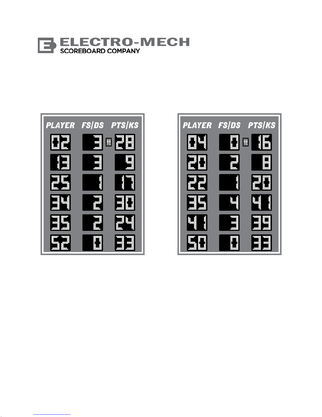
Display Features:
• 12 each 2-Digit Player Number (six sets for Guest, six sets for Home), Red,
6 inches tall, to 99
• 12 each 2-Digit Player Fouls/Digs (six sets for Guest, six sets for Home), Green,
6 inches tall, to 99
• 12 each 2-Digit Player Points (six sets for Guest, six sets for Home), Amber,
6 inches tall, to 99
Additional Standard Scoreboard Features:
• All serviceable components accessible from the front of the cabinet
• Built-in AC power cable, 6 feet long (one per cabinet)
• Data output port for daisy-chaining additional displays
• Eye bolts for lifting
• Integrated mounting tabs
Control Console:
• The console features custom software running on an internal microprocessor, a
32-character LCD display, a 37-button se al ed me mbra ne k eypad, and a 6-ft.
power cord. The console enclosure consists of an ABS plastic base and top with
a metal back plate.
• Four data output ports can each directly drive a player statistics display through a
single cable run and indirectly drive up to ten displays in perfect synchronization
via daisy-chaining. The number of synchronized displays is practically limitless
when using the optional ScoreLink RF communications system.
• The software includes support for 50 levels of brightness.
Optional Equipment and Features:
• Data cable for hard-wired installations (two runs required)
• ScoreLink RF communications system for wireless data transmission (two
receiver units required)
• Hard carrying case for control console and accessories
• Non-illuminated, illuminated, and fully electronic ID panels, message centers,
and video displays
• Stadium Sound Systems
Page 6 800.445.7846 · www.electro-mech.com

Revised November 11, 2015 LX2056 Owner's Manual
Power Requirements:
• Each LX2056 player statistics display requires one circuit providing 2.1 amps
120 VAC, 60 Hz
• Power enters each cabinet via an attached 6-foot long cord designed to plug into
a standard (NEMA 5-15R) power receptacle.
• The control console requires one circuit providing 0.5 amps, 120 VAC, 60 Hz via
standard (NEMA 5-15R) power receptacles.
• Electro-Mech recommends installing a dedicated breaker to control power to the
player statistics displays.
• All power receptacles must be properly grounded.
Mounting Requirements:
• In its standard configuration, this scoreboard display set is designed for indoor
use, and each cabinet may be mount ed on a wall or suspended from the ceiling.
• To use the standard mounting tabs for installation on a wall, the installer must
securely attach two lag bolts, or similar hardware, with a maximum diameter of
3/8 inches. The mounting tabs are spaced 40 inches from center to center.
• Each display cabinet may be suspended from the two eye bolts attached along
the top of the frame. These eye bolts are spaced 36 inches center-to-center and
have a 1-inch diameter opening to accept chain or cable.
Warranty Information:
• The standard limited warranty covers factory labor on parts returned to ElectroMech within five years of the scoreboard's date of invoice.
• The complete standard warranty statement is included near the end of this
document.
• Additional support plans are available.
www.electro-mech.com · 800.445.7846 Page 7

LX2056 Owner's Manual Revised November 11, 2015
PLANNING YOUR SCOREBOARD INSTALLATION
A good plan is important to the success of any project, and installing player statistics
panels is no exception. An important first step in planning for your stat panels is
determining the optimal location. Key factors here are accessibility and visibility.
By "accessibility" we mean the ease with which you can get people, equipment, cabling,
etc. to the player statistics displays during installation, as well as ease-of-access for
future service. If you position the panels so that using a lift or ladder to reach them is
impractical, you will almost certainly add cost to the installation and to service calls.
By "visibility" we mean the ease with which spectators, participants, and the operator of
the stat panels can see the displays. Because every sports facility is unique, there is no
one-size-fits-all way to describe the perfect stat panel location. We can tell you that the
vertical placement of the displays should be high enough to give spectators a clear line
of sight over the heads of players but low enough to allow fans to glance up from the
game and check the stats without straining their necks. For safety, you will want to
keep the bottom the cabinets at least eight feet above the floor (to prevent people from
smacking their heads against them).
For some indoor facilities, it is important to make sure people cannot – accidentally or
intentionally – interfere with the player statistics displays or cables connected to them.
For example, indoor stat panels are sometimes mounted along the front facade of
balcony seating. This can make it tempting for fans to reach over the balcony and touch
the panels, snag a cable, drop a soda on them, or otherwise make a nuisance of
themselves. One solution would be to install a shield above any scoreboard in this
position.
If you are planning for the construction or renovation of a new facility, then you will likely
have more options for locating your player statistics displays. In addition, you may be
able choose helpful posi ti ons for el ect r ic al out l ets , pla n for condui ts , and cont r ol ot h er
details that will make installation, operation, and service easier. Your scoreboard sales
rep should be able to answer questions and offer advice that will help you with these
plans.
If you are adding this player statistics panel set to an existing facility, your options may
be more limited. In some cases, we can modify the stat panel cabinets to meet special
needs. An example of this would be accommodating power entry through the back of
the cabinet rather than via the standard power cable on top. These sorts of details must
be worked out prior to the release of a scoreboard order. Your sales rep can guide you
through the process.
The sections that follow in this document primarily discuss the details of the mechanical
and electrical installation of a single set of player statistics panels. If your project
includes additional pan el s, clock s, sc or ebo ar ds, or other electronic displays, please
Page 8 800.445.7846 · www.electro-mech.com

Revised November 11, 2015 LX2056 Owner's Manual
check with your scoreboard sales rep to make sure you have any project level
documentation you may need.
Before You Spend Your Time and Money...
Please keep in mind that the dimensions and other details referenced throughout this
document are specific to the standard configuration of this player statistics scoreboard
model. Before purchasing materials, running cabling, etc. you should verify with the
factory that you have the right documentation for your particular project.
It is possible that a government agency, such as your local city council, will require a
building permit or other documentation and approval forms related to the installation and
operation of your stat panel displays. In some cases the installation plan may require a
stamp from a locally licensed Professional Engineer (P.E.).
www.electro-mech.com · 800.445.7846 Page 9
 Loading...