

ELECTROMATIC WTT-220X, WTTM-220X Instruction Manual
p
n
A
5
3
o
INSTRUCTION MANUAL
INSTRUCTION
MANUAL
Wire Terminal Tester
Wire
Terminal
Tester
WTT‐220X/WTTM‐220X
ELECTROMATICEqui
60
Cedarh
mentCo.,I
0Oakland
urst,NY11
516‐295‐4
Checkline.c
c.
ve
16
00
m

Co nte nt
1. Safe ty Prec autions .......................................................................................................................................................................... ....... ........ ... 2
2. G ene ra l Info rmatio n ....................................................................................................................................................................... ....... ....... .... 2
2.1. Sc ope o f Sup ply, unpac king and Se tting Up ........................................................................................................................................ 2
2.2. Ernerg y Ha rvesting (m a nua l p ull te ster FMT-W30 o nly) ........................................................................................................................ 2
2.3. Attac h the 24V DC po wer sup p ly (mo torize d pull teste r WTTM-220Xo nly) ............................................................. ........ ....... ....... ... 2
2.3 Instrume nt o ve rvie w ..................................................................................................................................................................... ........ ....... 3
3. O pe ra ting pro c e dure s ....................................................................................................................................................................... ....... ....... 3
3.1 Turn the instrum e nt O N/ O FF ................................................................................................................................................................... ... 3
3.2 Ge ne ra l info rmatio n a b o ut the disp la y und func tio n o f the keyp a d d uring and in be twe e n the measure me nts .................. 3
3.3 Pre paring the me asureme nt .................................................................................................................................................................. ... 4
3.4 Start me a suring (Auto Ze ro ) with m a nua l p ull teste r WTT-220X .................................................................... ....... ....... ........ ....... ....... ... 5
3.6 Sta rt m e a suring (Auto Zero ) with m o to rize d p ull te ste r WTTM-220X .......................................................................... ....... ....... ........ ... 5
4. Te nsile fo rc e limit c ontro l ................................................................................................................................................................. ....... ....... ... 7
4.1. Se tting o f limits ................................................................................................................................................................... ....... ....... ........ ... 7
5. Da ta tra nsfe r a nd ge ne ra ting a te st re po rt w ith FMT-W_C o nne c t ........................................................................ ....... ....... ........ ....... ..... 7
5.1 Syste m re quire ments ........................................................................................................................................................................ ....... .... 7
5.2 Insta llation / Ac tiva te the Exc e l Add In ................................................................................................................................................. ... 7
5.3 Sta rt FMT-W_Conne c t ......................................................................................................................................................................... ....... . 9
5.4 Sa ve and p rinto ut me a suring p ro to c o l ............................................................................................................................................ ..... 10
6. G ene ra l se ttings (P1), Se tting o f me mory (P2) a nd re se t wo rks defaults (Po ) ...................................... Erro r! Bo okm a rk no t de fine d.
7. Te c hnic al d ata ........................................................................................................................................................................ ...... ..... .... ...... ... 1 1
8. Mainte na nc e a nd c alibra tio n ............................................................................................................................................................... ...... . 1 1
8.1 5-Years e xte nd e d wa rranty ..................................................................................................................... Erro r! Boo kmark not d e fine d.
8.2 Re g iste r fo r up dates .................................................................................................................................. Erro r! Bo okma rk no t d e fined .
9.0 Tro ub le sho o ting (FAQ) ........................................................................................................................................................... ..... ...... ..... .... . 11
10.0 Ac c e ssories (Exc ha ng able te rm ina l fixtures) .................................................................................................................................. ..... .. 1 2
1
Tha nk you fo r c ho o sing o ne o f o ur high q ua lity instrume nts. Ple a se re a d the entire o pe ra tion manua l tho roug hly be fo re using
this instrument fo r the first time. The info rm a tio n c o nta ine d he rein w ill he lp you to a c hie ve a c c ura te a nd re p ro d uc ib le re sults
a nd to avo id misuse o r da ma ge s.
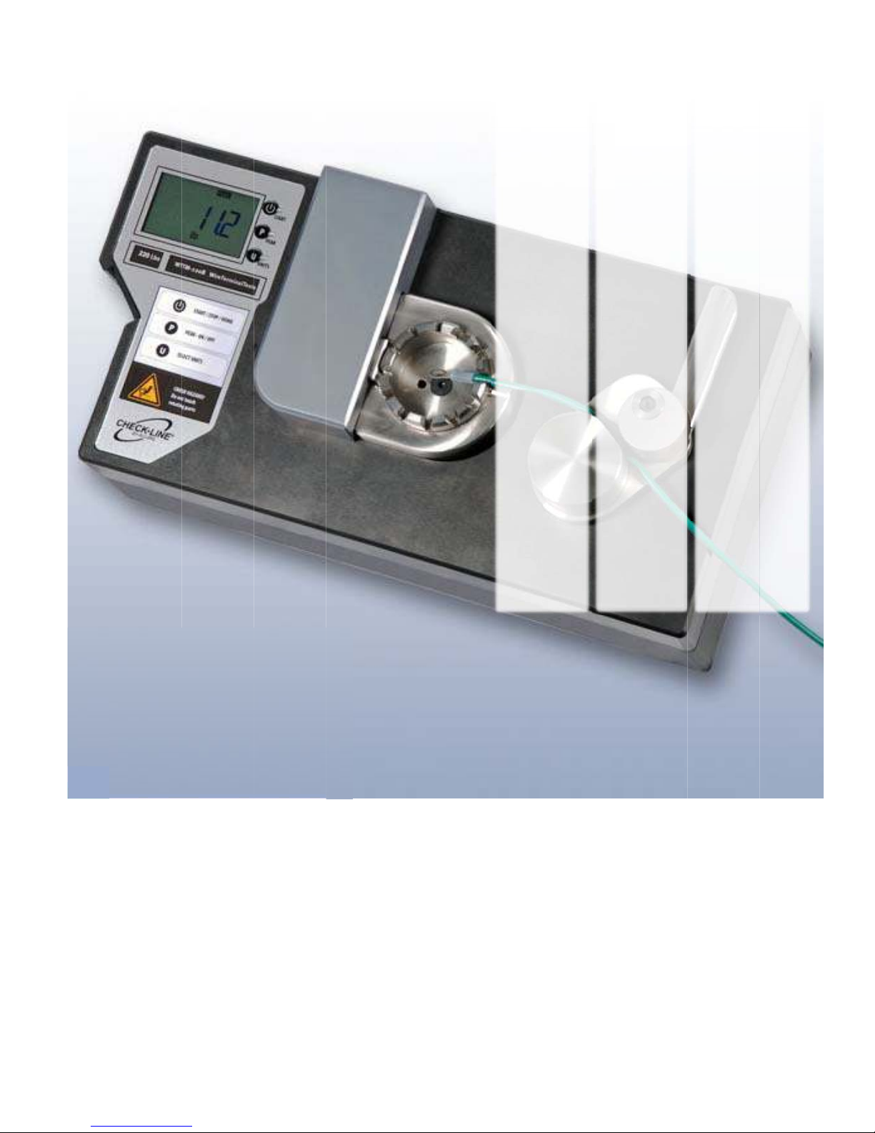
This instrume nt is d e sig ne d fo r me a suring te nsile stre ng th o f so ldere d o r so ld e r-fre e (c rimp e d ) c a b le jo ints with e nd slee ve s,
p ins, so ld e r pins or sim ila r w ire termina l c o mp o nents in the fie ld o f qua lity c ontro l o r d e sig n va lid a tio n.
1. Safe ty Pre c autio ns
The lo ad c e ll c an b e d a maged when the me a suring syste m is o ve rloaded. The ma xim a l measuring range limit
o f 1000N (100kg /220lb) must no t be e xc eeded.
Transp o rt a nd store the instrum e nt with c a re. This re d uc e s the risk o f d a mage to the lo a d c e ll, c a use d b y
a c c id e ntal me c ha nic a l e ffec ts.
O pe ra te the instrum e nt in appropria te e nviro nm e nts o nly. The instrum e nt is equip p e d w ith a te mpera ture
c o mpe nsa tio n fo r 0°...40°C . Use the instrum e nt in this temp era ture ra ng e o nly.
Ve ry fre q uent use o f the mo to rized pull te ste r FMT-W40(highe r 1 test c yc le pe r m inute ) may le a d to
o verhe a ting o f the mo to r. A o ve rheat pro te c tio n is imp leme nte d ; ne ve rthe le ss yo u m ay use the instrume nt in
e nviro nments up to 30°C (86°F) o nly.
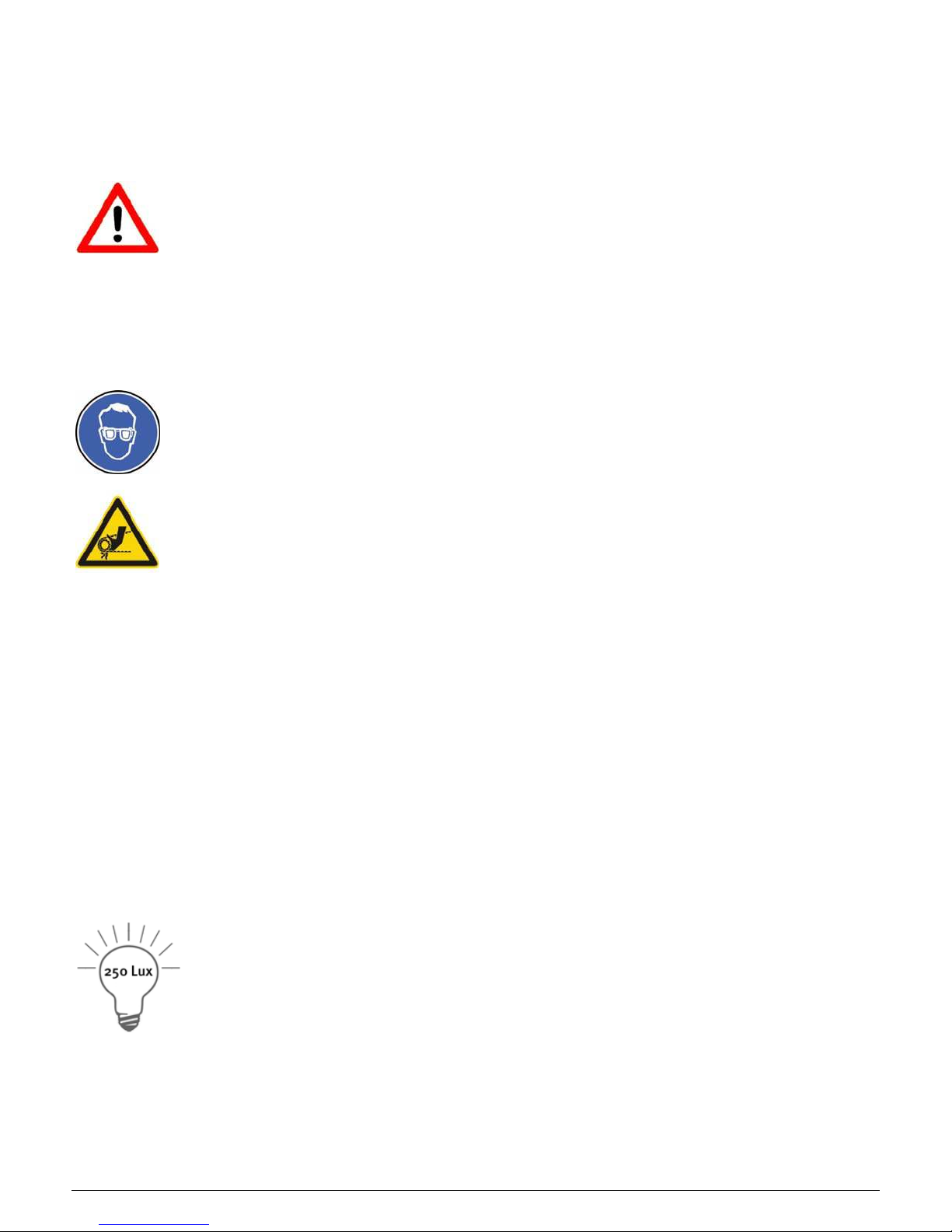
Due to the na ture of the material small partic le s ma y o c c ur in the mo ment o f the te nsile b re ak o f wire s. Yo u
may we a r p ro te c tio n gla sses a nd p ro te c tio n g lo ve s in o rd er to p re ve nt injurie s.
Do n’ t to uc h d uring the p ull te st o r while the ro lle r c a m re turns to its ho m e p o sition the ro ta ting p a rts o f the
instrum e nt. Do no t ta ke yo ur ha nd into the g a p b e twe e n the c a b le , the te rm ina l adapter a nd c la mp c a m. In
spite o f the lo w sp e e d or the ma nua l opera tio n o f the leve r you ma y injure yo urse lf.
2. G e ne ra l Inform a tio n
2.1. Sc o p e o f Supply, unpac king and Se tting Up
The sc o pe o f sup p ly c o nsists o f:
Me asuring instrume nt with inte g ra te d e lec tro nic s
Ha nd le ve r o r ro lle r g rip
USB Inte rfac e c a b le fo r optio na l so ftware FMT-W_Co nne c t
CD with so ftwa re FMT-W_-Co nne c t (w itho ut lic ense ke y)
Ope ra tio n manua l
24V DC p owe r sup ply (Part. no .: FMT-958) fo r mo to rized pull teste r WTTM-220X
Re mo ve the tra nsp o rta tio n c o ver a nd positio n the ma in instrum e nt on a le ve l, sta ble surfa c e. The surfac e sho uld b e c le an and
g re a se -fre e , so tha t the instrum e nt doe s no t slip. Ple a se b e a r in mind tha t the instrume nt we ig hs a p pro ximately 14 kg .
Ple ase re ta in the tra nspo rt p a c king in c a se yo u wo uld like to re turn the instrume nt fo r the re c omm e nd ed annua l re c a lib ra tio n.
2.2. Ene rg y Ha rve sting (manual pull te ste r WTT-220X only )
The instrume nt utilize s, a lso w he n turne d o ff, the a mbie nt lig ht a t the work plac e a s e ne rg y so urc e a nd
c harg e s an inte rnal sto ra g e , to e nsure that te sts c an b e made e ve n if the so lar c e ll is c o vere d fo r a sho rt
while. Afte r sto ring the instrume nt fo r mo re than 2 mo nth in the d a rk, yo u sho uld e xpose it at le a st for 8
ho urs in re g ula r working e nviro nment (> 250 Lux) b e fo re use .
2.3. Attac h the 24V DC powe r supply (m o to rize d p ull te ste r WTTM- 220X o nly )
The mo torize d p ull te ste r WTTM-220Xis d e livere d with a n universa l po wer supply fo r 110-220VAC (50/60Hz) and po we r c o rd s
with EU-plug and US-plug . Cho o se the p o we r c o rd ac c ord ing ly a nd c o nne c t first the DC p lug into the so c ke t o n the re a r sid e
o f the instrum e nt. Then yo u ma y c o nne c t the p o we r c o rd to yo ur wall so c ket o r AC powe r ne t.
The powe r c onsump tio n is re la te d to the o p e ration sta te o f the m o to r, the 3A po wer sup ply de live rs a lw a ys e no ugh e ne rg y to
g e ne ra te the a c tio n. Yo u may no t re p la c e it b y any o the r po we r sup ply but the d e live re d o ne (Pa rt no .: FMT-958). In c ase yo u
2
d o no t utilize the instrume nt fo r a lo nger p e rio d, yo u may disc o nne c t fro m the po wer ne t in o rd e r to pre ve nt waste o f ene rg y
in standby mode.
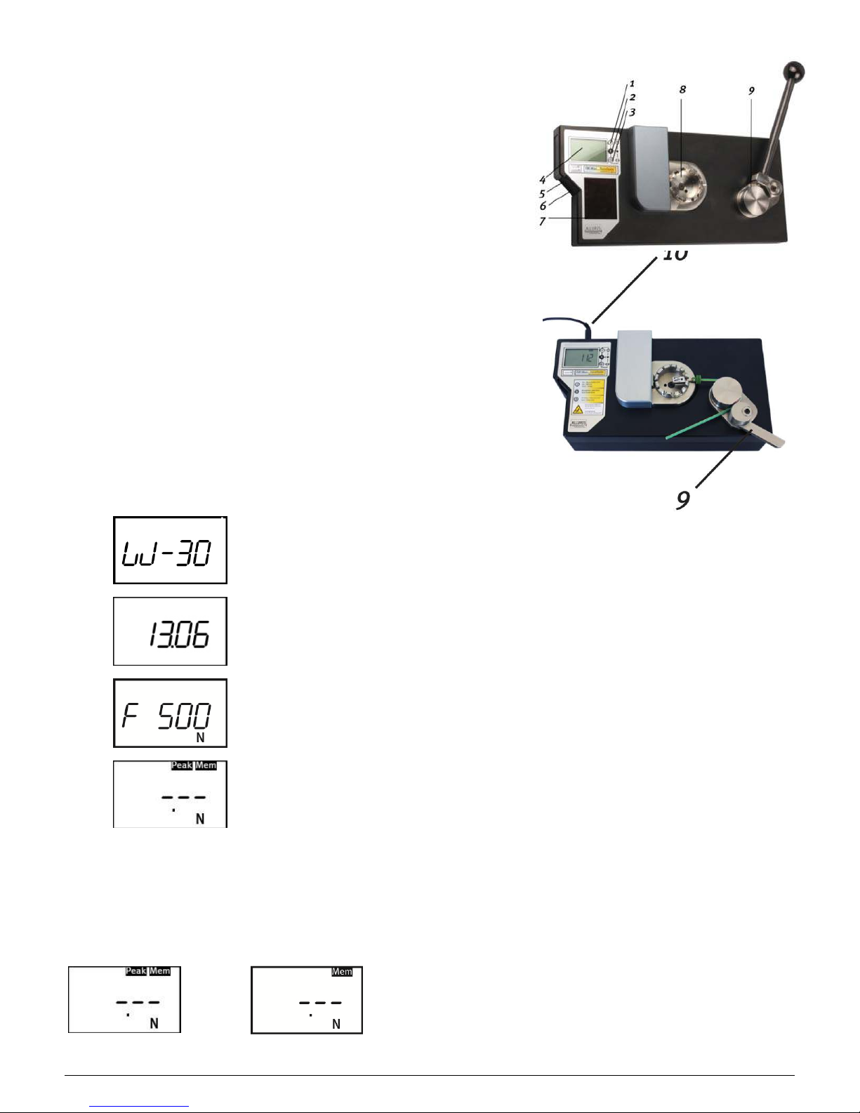
2.3 Instrum e nt ove rvie w
1. Sta rt Butto n turns the instrument on a nd o ff (keep p re sse d fo r > 2s) a nd to sta rt the
measureme nt.
2. P Button to togg le b e twe e n Pe ak a nd Real-Time d isp la y mode .
3. U-Butto n toggle s be twe en me asuring units.
4. Display with:
5-d ig it indic a tio n o f the me asured va lued and me asuring units;
indic ation o f the o pe ra tio n mode , memo ry a nd limits;
ind ic a tio n o f re sults with up /do wn po inte rs fo r te nsile forc e limits.
5. USB- soc ket fo r d ata tra nsfe r w ith FMT-W_C onne c t so ftwa re to pro duc e a test
pro to c o l.
6. Hiro se -so cket fo r se rvic e, ad justing the lo ad -c e ll and limit sig nal output.
7. Sola r c ell to po we r the instrument without USB interfa c e c o nne c ted.
8. Te rm ina l a da pter with 12 slo ts to plac e the c o nne c to r.
9. Rotating wire c lam p w ith hand le ve r to c la mp a nd pull the c a ble . Mo to rize d ve rsio n
WTTM-220X with e cc e ntric ally sp ring lo ade d ro lle r g rip.
10. Mo torize d versio n WTTM-220X DC- soc ket fo r 24V p owe r supp ly and re d status LED.
3. O pe ra ting pro c edure s
3.1 Turn the instrume nt ON/ OFF
Sw itc h the instrume nt o n b y pressing the Sta rt Button Ta ste until all disp lay
symb o ls lig ht up . Afte r a se lf-te st ro utine 3 informatio n d isplays are sho wn to
inform ab o ut the mode l number, the re c o mme nd e d d a te o f ne xt c a lib ra tio n
a nd the no minal m e a suring ra ng e (Fn). To turn the instrume nt off yo u m a y p re ss
the Sta rt Button fo r 3 se c o nd s, else the AUTO -O FF func tio n will turn the instrum e nt
o ff a uto ma tic ally (se e c ha p. 6)
.
Ind ic a tio n o f the instrume nt type
Display ne xt re c ommended c a lib ra tio n d ate (YY.MM)
Disp la y me asure me nt ra ng e [N]
Start displa y with de fa ult se tting; mo de PEAK w ith d ra g
func tio n a nd MEM fo r a c tive me mo ry and c a lc ulatio n
o f sta tic a lly va lue s.
3.2 G e ne ra l info rm atio n a bout the display und func tio n o f the ke ypa d during and in b e twe e n the
me asure me nts
Afte r the se lf-te st ro utine the d isp la y shows the symbols PEA K a nd MEM and the SI-d im e nsio n Ne wto n [N]. The se symbols
ind ic a te the d e fa ult setting in o p e ratio n m o d e PEAK w ith hig h m e a suring ra te (a p p . 1kHz) and dra g func tio ns with the
possib ility to sa ve measuring re sults fo r statistic al c alc ula tio ns. Whe ne ve r you want to c ha ng e the d e fa ult se tting s, yo u ha ve to
re turn to this d ispla y.
If yo u w a nt the update d a c tua l fo rc e v alues to b e shown during
te sting instead o f the d ra g func tio n w ith PEAK value s, yo u press the P
S
<<
>>
Button. The PEA K symbol starts fla shing . Ple a se c o nsid e r tha t in the
c omb ina tion o f this mo d e with me mo ry is no t a dvisa ble a s the me mory
a lw a ys c a p ture s the a c tua lly displa ye d va lue. By pressing the P Button
a g a in yo u re turn to the PEAK mode with d ra gging func tio n.
3

0
>>>
3.3 Pre paring the m e a sure me nt
Se lec t the smallest slo t suita b le fo r the te st sa m p le d ia m e te r a nd ro ta te the fixture so the
sele c te d slo t is in the 3 o ’c loc k p ositio n, c lo sest to the wire c la mp fixture .
Pla c e the c a b le c onne c tio n into the a dapte r, so tha t the sle eve o f the c able c o nne c tor stays
sec ure ly inside the ring a nd c anno t b e p ulle d o ut thro ug h the slo t.
0
>>>
If yo u wo uld like to ge t your m e asuring va lues
in o the r units the n the SI-d imension N yo u
p re ss the U Button. Every time yo u pre ss the
b utton (in sta rt menu o nly) the units c ha ng e s
b e twe en N >> kg >> Lb
The wire c la mp fixture should be po sitio ne d in the full o pe n p o sitio n.
The manua l p ull te ste r nee ds a fre e leng th o f the c a b le o ff minimum 14c m (5.5“), the
motorize d ve rsion a leng th o f 10c m (4“ ).
So ft c ab le c o ating s ma y slid e thro ugh the c lamp fixture o r b e pulle d o ut o f the c rimp sle e ve .
In this c a se ple ase c ut o ff the c o a ting in 4c m to 8c m (2...3“ ) d ista nc e to the c a b le jo int und e r
te st.
4
 Loading...