


– 1 –
1.0 Introduction . . . . . . . . . . . . . . . . . . . . . . . . . . . . . . . . . . . . . . . . . . . . . . . . . . 02
2.0 Unpacking and Contents . . . . . . . . . . . . . . . . . . . . . . . . . . . . . . . . . . . . . . . 03
3.0 Setup . . . . . . . . . . . . . . . . . . . . . . . . . . . . . . . . . . . . . . . . . . . . . . . . . . . . . . . . 04
4.0 Charging the Battery . . . . . . . . . . . . . . . . . . . . . . . . . . . . . . . . . . . . . . . . . . 04
5.0 AC Operation . . . . . . . . . . . . . . . . . . . . . . . . . . . . . . . . . . . . . . . . . . . . . . . . . 04
6.0 Overview of Keypad and LCD Display . . . . . . . . . . . . . . . . . . . . . . . . . . . 05
7.0 Overview of Operating Modes . . . . . . . . . . . . . . . . . . . . . . . . . . . . . . . . . . 06
8.0 Changing Units of Measurement . . . . . . . . . . . . . . . . . . . . . . . . . . . . . . . . 06
9.0 General Operating Procedures . . . . . . . . . . . . . . . . . . . . . . . . . . . . . . . . . . 07
9.1 Additional Operating Information
10.0 Adjusting Advanced Settings . . . . . . . . . . . . . . . . . . . . . . . . . . . . . . . . . . . 09
10.1 Temperature Compensation
10.2 Selecting the Baud Rate of the RS232 Interface
10.3 Switching off the Auto-Power Off Function
10.4 Change the Refresh Rate of the Display
10.5 Flow Chart: Steps Required To Change Advanced Settings
11.0 Data Transfer (Model WT-110RS only) . . . . . . . . . . . . . . . . . . . . . . . . . . . 013
11.1 RS-232 Interface
11.2 Analog Output
12.0 Calibration . . . . . . . . . . . . . . . . . . . . . . . . . . . . . . . . . . . . . . . . . . . . . . . . . . . 015
13.0 Troubleshooting Guide . . . . . . . . . . . . . . . . . . . . . . . . . . . . . . . . . . . . . . . . 017
14.0 Specifications . . . . . . . . . . . . . . . . . . . . . . . . . . . . . . . . . . . . . . . . . . . . . . . . 018
15.0 Dimensions . . . . . . . . . . . . . . . . . . . . . . . . . . . . . . . . . . . . . . . . . . . . . . . . . . . 019
16.0 Warranty . . . . . . . . . . . . . . . . . . . . . . . . . . . . . . . . . . . . . . . . . . . . . . . . . . . . . 020
TABLE OF CONTENTS
– 20 –
16.0 Warranty
ELECTROMATIC Equipment Co., Inc. (ELECTROMATIC) warrants to the
original purchaser that this product is of merchantable quality and confirms in kind
and quality with the descriptions and specifications thereof. Product failure or malfunction arising out of any defect in workmanship or material in the product existing at
the time of delivery thereof which manifests itself within one year from the sale of
such product, shall be remedied by repair or replacement of such product, at
ELECTROMATIC’s option, except where unauthorized repair, disassembly, tampering,
abuse or misapplications has taken place, as determined by ELECTROMATIC. All
returns for warranty or non-warranty repairs and/or replacement must be authorized by
ELECTROMATIC, in advance, with all repacking and shipping expenses to the
address below to be borne by the purchaser.
THE FOREGOING WARRANTY IS IN LIEU OF ALL OTHER WARRANTIES,
EXPRESSED OR IMPLIED, INCLUDING BUT NOT LIMITED TO, THE WARRANTY OF MERCHANTABILITY AND FITNESS FOR ANY PARTICULAR PURPOSE OR APPLICATION. ELECTROMATIC SHALL NOT BE RESPONSIBLE
NOR LIABLE FOR ANY CONSEQUENTIAL DAMAGE, OF ANY KIND OR
NATURE, RESULTING FROM THE USE OF SUPPLIED EQUIPMENT, WHETHER
SUCH DAMAGE OCCURS OR IS DISCOVERED BEFORE, UPON OR AFTER
REPLACEMENT OR REPAIR, AND WHETHER OR NOT SUCH DAMAGE IS
CAUSED BY MANUFACTURER’S OR
SUPPLIER’S NEGLIGENCE WITHIN ONE YEAR FROM INVOICE DATE.
Some State jurisdictions or States do not allow the exclusion or limitation of
incidental or consequential damages, so the above limitation may not apply to you.
The duration of any implied warranty, including, without limitation, fitness for any
particular purpose and merchantability with respect to this product, is limited to the
duration of the foregoing warranty. Some states do not allow limitations on how long
an implied warranty lasts but, not withstanding, this warranty, in the absence of such
limitations, shall extend for one year from the date of invoice.
ELECTROMACTIC Equipment Co., Inc.
600 Oakland Ave. Cedarhurst, NY 11516—USA
Tel: 1-800-645-4330/ Tel: 516-295-4300/ Fax: 516-295-4399
– 2 –
1.0 INTRODUCTION
Thank you for selecting the CHECK•LINE WTT-110 Wire Terminal Pull Tester for
your requirements. With correct use and proper care this product should provide
many years of precise and accurate testing. Please read the entire operation manual
thoroughly before using this instrument for the first time. The information contained
herein will help assist users to achieve accurate and repeatable results as well as
prevent damage with improper set-up or operation.
This instrument is designed for measuring tensile strength of soldered or solder-free
cable joints with end sleeves, pins, solder pins or similar wire terminal components
in the field of quality control or design validation.
Safety Precautions
Wear appropriate eye protection at all times.
The load cell can be damaged if the internal measuring system is overloaded.
Do not exceed the maximum measuring limit of 50 Kg (110 lbs. or 500N).
Transport and store the instrument with great care. This reduces the risk of
damage to the load cell or other minor mechanical problems which can result
in inaccurate measurement results.
Operate the instrument in appropriate environments only. The instrument
is equipped with a temperature compensation for a temperature range of
32 to 120 °F (0° to 40°C) and should be used in this temperature range only.
Do not expose this device to liquid or operate in high-humidity environments.
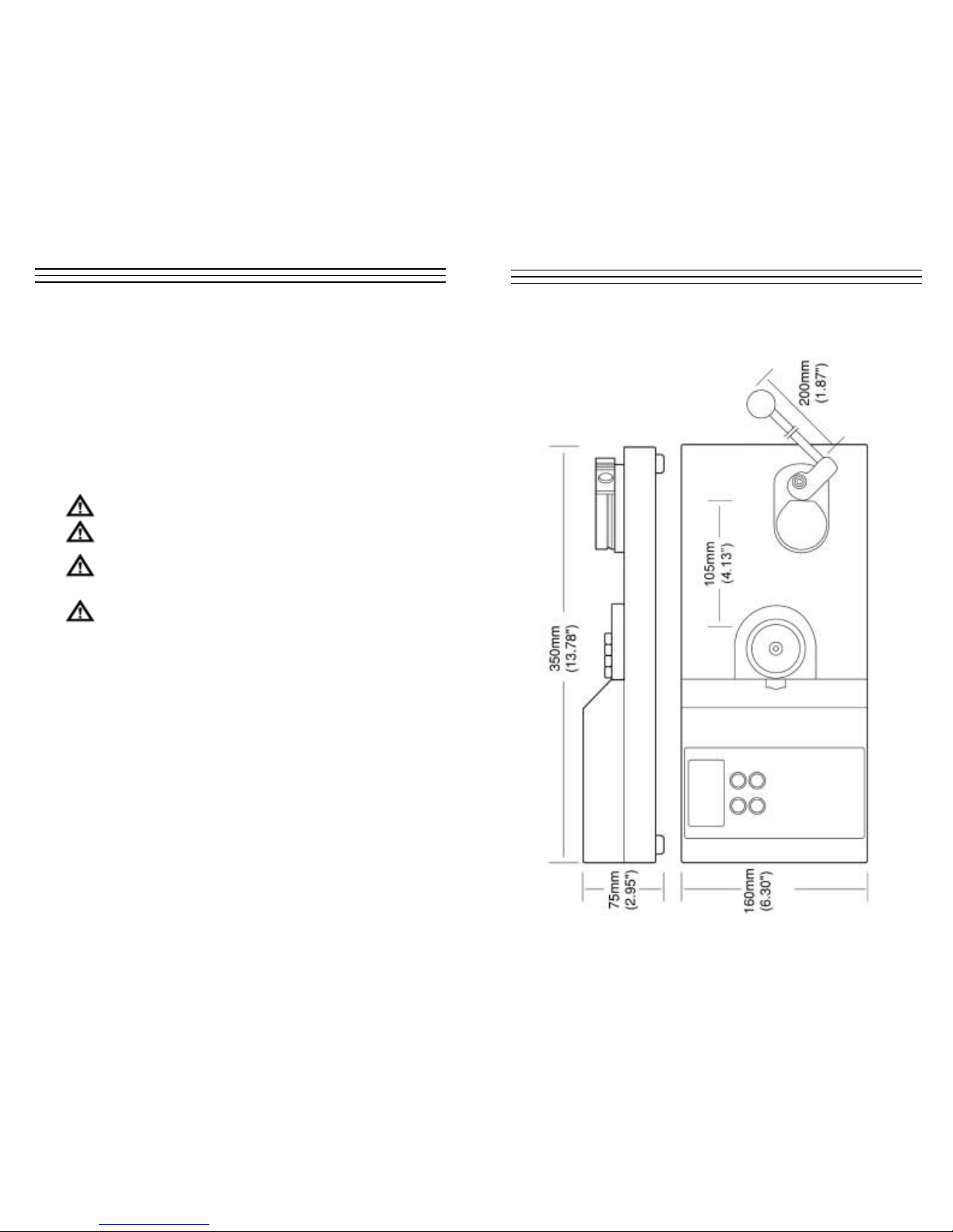
– 19 –
15.0 Dimensions
– 3 –
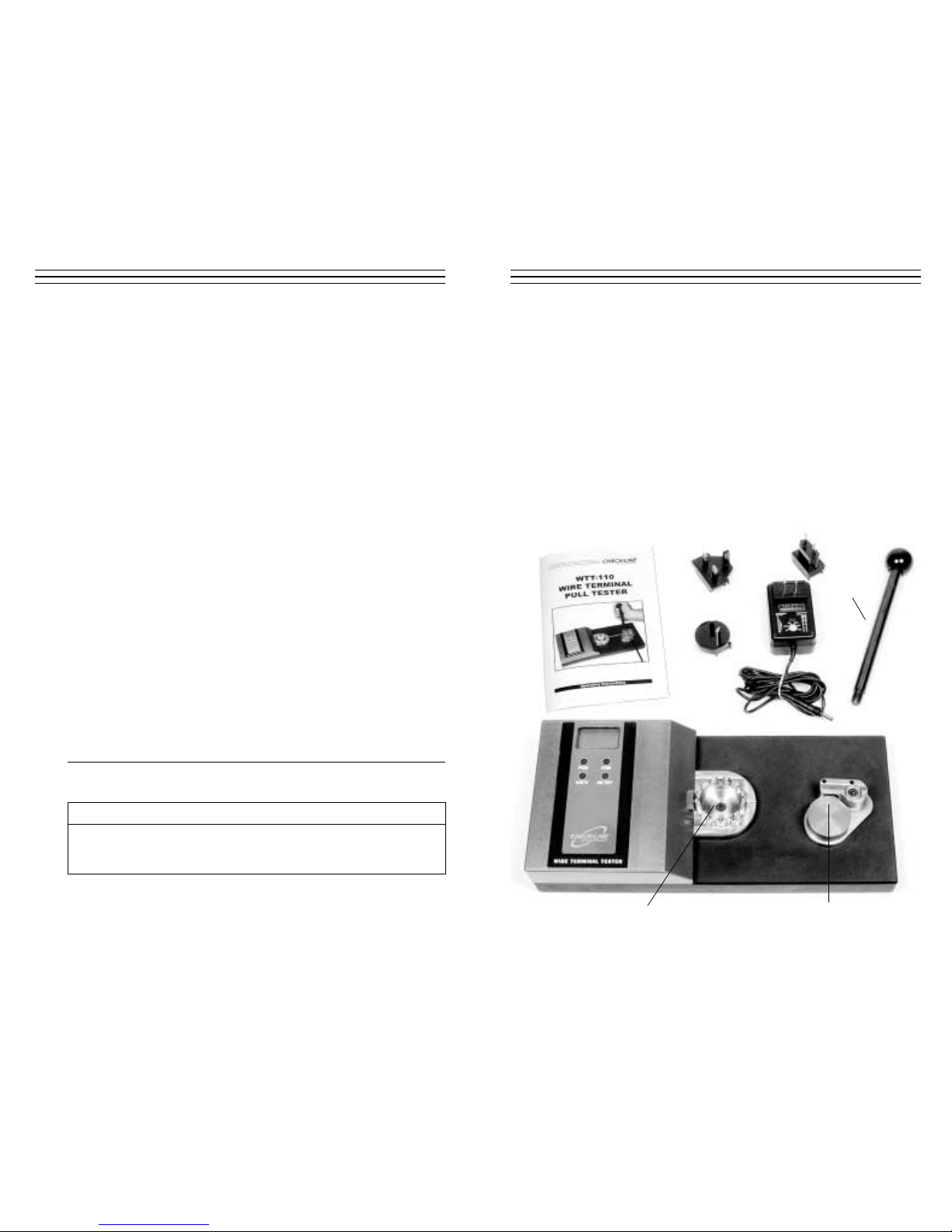
2.0 UNPACKING & CONTENTS
Remove the unit carefully and check the unit appears undamaged in shipment.
Check to see that all of the supplied items are contained in the box (see below).
Retain packaging materials in the case that the unit needs to be returned to the manufacturer or distributor.
■ Main instrument table
■ Separate hand lever with ball end
■ 9V DC battery charger 100 to 240 VDC (50 to 60Hz) with Euro/US/UK
plug adaptor
■ Operating instruction manual
■ Connection cable for RS232C (WTT-110RS model ONLY), not shown
Lever
Wire CLAMP FixtureWire TERMINAL Fixture
– 18 –
14.0 SPECIFICATIONS
Measuring Range* 0–50 Kg / 0–110 lbs / 0–500N
(units selected via keypad)
Resolution 0.01Kg / 0.1 lbs / 0.1 N
Terminal adapter
slot width (mm) 0.5, 0.8, 1.0, 1.4, 1.5, 2.0, 2.5, 3.0, 3.5, 4.0, 5.0, 6.0
Accuracy ±0.5% F.S. or better
Operating Mode
Continuous Displays actual value in Kg, lbs. or N
Peak-Hold Displays peak value in Kg, lbs. or N
Wire Diameter
SAE AS7928 II AWG 8. . .30
IEC 60352-2 Cross section 0.05. . .10mm
2
Maximum 0.236" (6mm)
Overload 200% Full Scale (LCD indicator at 120%)
Display LCD, 4–1/2 digit, 12mm high
Memory Peak Value
Power Supply Internal NiCd battery, supplied with
AC adapter/charger
(100-240V/50-60 Hz)
Temp. Range
Operating 32 to104 °F (0 to 40 °C)
Storage –4 to 140 °F (–20 to 60 °C)
Weight, approx. 30.8 lbs. (14 Kg)
Dimensions 14.2" x 6.3" x 2.95" (360 x 160 x 75mm)
Material Anodized aluminum, steel and stainless steel
* Low-range model available on special order basis.
Model WTT-110RS Only
Interface
Serial 2400 KB/8/N/1/ None (selectable baud rate)
Analog 0-1VDC
– 4 –
3.0 SETUP
Place the WTT-110 Wire Terminal Tester on a level and stable work area where the
user can perform the testing in a comfortable manner. The surface should be clean and
grease-free, so that the instrument does not slip.
Make sure that there is no residue from the packaging materials stuck under and around any of the
operating components especially in the recessed
area around the rotating terminal fixture (see photo)
and under the lever arm base plate, etc.Use of
compressed air to clear any debris from these
areas is recommended.
Please note that the instrument weighs approximately 30 pounds (14 kg), so please use
necessary precautions when lifting and moving. We suggest that the location is in close
proximity to an AC-Power outlet.
Locate the lever and screw it in to the
threaded hole in the rotating wire clamp
fixture, as shown in the photo. Turn the
lever in a clockwise direction to screw-in.
Continue until it is “hand-tight.” DO NOT
OVERTIGHTEN.
4.0 C
HARGING THE BATTERY (REQUIRED BEFORE FIRST USE)
For safety reasons, the WTT-110 is supplied with the batteries fully discharged.
To obtain maximum battery life we recommend that you charge the internal NiCd
battery for approximately 18 hours before first using this instrument the first time.
Select the appropriate plug adapter for the outlet type and country of use. Plug the
charger into an AC-outlet and plug the other end into the receptacle on the left side of
the WTT-110. Charge the batteries.
Note: The BAT indicator is shown on the display when the batteries are being charged
and turns off when the batteries are fully charged. When the batteries are nearly
discharged, the "LO BAT" indicatory will blink on and off.
5.0 AC-O
PERATION
The WTT-110 can be operated using the AC-Adapter/Charger. The batteries are being
recharged while plugged into the AC power source. Total battery recharge time will be
significantly longer then if recharged while turned off.
– 17 –
13.0 TROUBLESHOOTING GUIDE
If any error codes are shown on the display, first try turning the power off and then
back on again. If the code is still on the display, refer to the chart below.
AWG Cross-Section Cable Diameter SAE AS7928 IEC 60352 Part 2 UL 486 C
30 0,06 mm_ 0,36 mm 6 N 6 N
28 0,09 mm_ 0,38 mm 11 N 11 N
26 0,14 mm_ 0,48 mm 32 N 18 N 18 N
24 0,22 mm_ 0,61 mm 45 N 28 N 28 N
22 0,34 mm_ 0,76 mm 67 N 40 N 40 N
20 0,56 mm_ 0,97 mm 85 N 60 N 45 N
18 0,93 mm_ 1,27 mm 170 N 90 N 45 N
16 1,25 mm_ 1,44 mm 223 N 135 N 68 N
14 1,93 mm_ 1,80 mm 312 N 200 N 100 N
12 3,16 mm_ 2,29 mm 490 N 275 N 138 N
10 4,65 mm_ 3,10 mm 355 N
Size of Conductor UL 486A Table 12.1 SAE AS7928 Table II
AWG (mm2) Pounds (N) Pounds (N)
30 0.050 1–1.5 6.7 N/A N/A
28 0.080 2 8.9 N/A N/A
26 0.130 3 13.4 7 3.12
24 0.200 5 22.3 10 44.5
22 0.324 8 35.6 15 66.8
20 0.519 13 57.9 19 84.6
18 0.823 20 89.0 38 169.1
16 1.310 30 133.5 50 222.5
14 2.080 50 222.5 70 311.5
12 3.310 70 311.5 110 489.5
10 5.261 80 356.0 N/A N/A
DIN 41611/3 is replaced by DIN IEC 60352 Part 2 MIL-T-7928 is replaced by SAE AS7928 Table II
BS5B178 corresponds to IEC 60352 Part 2 UL486A corresponds to IEC 60352 Part 2
Industry-Based Standards, Specifications and Recommendations
Pull Test Specifications for UL, MIL and SAE
Small Display Condition Action
Minus side overload condition
Remove excessive load. If the display does not
return to normal operation, send unit in for repair
Plus side overload condition
The load exceeds 120% Remove excessive load
of its capacity
EEPROM reading error
Turn the unit off, then turn on again.If the
display does not return to normal operation,
send the unit in for repair
EEPROM writing error
OVM
OVP
OV+
OV–
ERR
- 3 -
ERR
- 4 -

– 5 –
6.0 OVERVIEW OF KEYPAD & LCD DISPLAY
1 Low Battery Indicator. Flashes when batteries need charging, turns off when fully
charged. Remains on while charging.
2 Peak Mode Indicator. Shown on display when configured for peak mode
(stores highest peak force until it is reset by pressing zero key)
3 Units Indicator. Displays currently selected units of measure (pounds, newtons
or kilograms). Changed by pressing UNITS key.
4 F or ce Value. Displays current or peak force value in user-selected units of measure.
5 PEAK Key. Turns on Peak Force Capture Mode. When selected, the highest peak
value will be shown on the display until reset by ZERO key.
6 UNITS Key. Selects desired units of measure. Each time this key is pressed, the
units will change from one to the next.
7 ZERO Key. Performs a “tare” on the system and resets display to zero. When in
peak mode, it erases the previously stored peak value.
8 ON/OFF Key. Turns the system on and off.
LL00--BBAATT
PPEEAAKK
LLbb
ff
00..00 00
PEAK
UNITS
ZERO
ON/OFF
1
2
3
4
5
6
7
8
– 16 –
Re-Calibration Procedures
1. Turn POWER off. Make sure the weight is NOT suspended from the sample.
2. Press and hold the UNIT, PEAK and ZERO keys simultaneously.
3. Press and release the On/Off key (while continuing to press UNIT, PEAK
and ZERO) until the smaller characters at the top of the display show CAL.
4. Release the UNITS, PEAK and ZERO keys.
5. The force gauge is now in calibration mode.
6. Press the UNITS switch. The display will show ZER after blinking SCN for
10 seconds.
7. The force gauge is now ready for zero point calibration.
8. Press ZERO key to confirm the zero calibration. Wait approximately 15–20
seconds. The display will change to show PEK after blinking SCN. Do not press
any other keys or disturb the instrument or weight during calibration.
9. Hang the 50 Kg calibration weight from the sample which is hooked on to one
of the teeth of the Wire Terminal Fixture. Make sure that the material path is
unobstructed and in a straight horizontal orientation. The force gauge is now
ready for full-scale calibration.
10. Press the PEAK key to begin full scale calibration. The display will blink SCN.
Do not press any other keys or touch the weight during calibration. After approximately 15– 20 seconds the display will blink END. Then after approximately 5
seconds the display blinks OK.
11. If calibration was successful, the display will show OK momentarily (see above
illustration). Press the UNITS key, then the power will automatically switch off.
12. If calibration was unsuccessful, the display will show ERR. Remove the calibration weight, then press the UNIT key and repeat the above procedure again.
CAL
–00–
“oK”
88888
“SCN”
–00–
ZER
88888
➔
“SCN”
88888
PEK
88888
➔
“SCN”
88888
“End”
88888
➔➔

– 6 –
7.0 OVERVIEW OF OPERATING MODES
The WTT-110 can be set to operate in one of two distinct operating modes: Peak
Capture or Average. In Peak Capture Mode, the system measures the force at a frequency of 1000 Hz (1000 times per second) and displays the highest force measurement. The peak value remains on the display until a higher force value is measured or
until the user presses the ZERO key.
In Average Measurement Mode, the system measures the force at a frequency of
1000 Hz (1000 times per second) and displays the average each time the display is
updated. The factory default display update rate is 3 times per second (1 time every
1/3 second).
Note: Refer to Advanced Setting, section 10, page 10, for additional information and
to change the update rate.
8.0 C
HANGING UNITS OF MEASUREMENT
The WTT-110 can display force measurements in any of the following theree engineering units:
■ lbf (pounds)
■ N (Newtons)
■ Kgf (kilograms)
To change the selected engineering units for display press UNITS key. Each time the
key is pressed, the units will change from one to the other as follows:
Lbf
Kgf
N
– 15 –
12.0 CALIBRATION
The WTT-110 Pull Tester has been calibrated in accordance with factory proceedures
and is certified to perform within the stated accuracy specifications shown in the
Specifications section found on page 18. Assuming the unit is handled with care
and operated as detailed in this manual it should remain accurate for an extended
time period. If however, it is subjected to forces that exceed its maximum range or
if it is not properly cared for, it might need to be recalibrated.
It is recommended that the calibration is verified at least on an annual basis and more
frequently if feasible. Normally, instruments of this type go out of tolerance from one
day to the next and rarely on a regular periodic basis.
A calibration procedure is provided in this manual, however it should only be performed by individuals properly trained for this type of service and with the appropriate
certified standards (known weights or secondary force measuring system such as a
load cell, etc.).
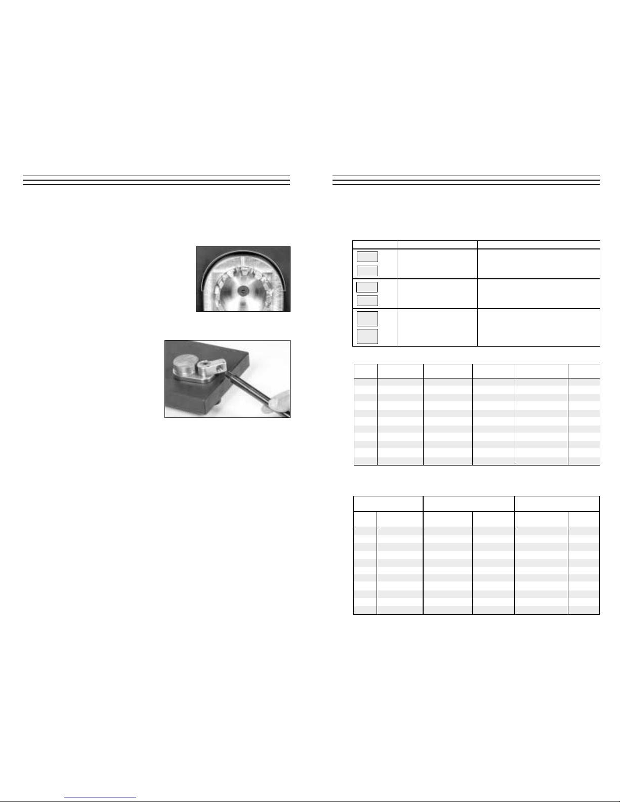
Re-Calibration Set-up
1. Remove the lever by unscrewing it in a
counter-clockwise direction and move
the Wire Clamp assembly out from the
path of the hanging sample.
2. Position the WTT-110 in a vertical
position so that the keypad & display
are at the top (refer to photo). Be sure
to secure it so it can not topple over
when the weight is attached.
3. Using a heavy-duty monofilament
(fishing line), wire or similar, suspend
a 50 Kg weight from one of the teeth
on the wire terminal fixture by hooking
a loop of the material over the selected
tooth.
4. Temporarily, remove the weight and
follow the Re-Calibration Procedures
shown on page 16.
■ Make sure that the
WTT-110 is well secured
in the vertical position.
Caution
■ Select a material that is strong
enough to support 50 Kg of weight.

– 7 –
9.0 GENERAL OPERATING PROCEDURES
1. Press On/Off key. During power-up, the WTT-110 performs a self-test routine.
During this procedure, the maximum capacity of the system will be temporarily
displayed in selected units of measurement. Then the unit should display zero.
Occasionally the last one or two digits might be something other then zero.
Additionally, the selected units will be shown.
2. Select the desired operation mode. To set for Peak Capture Mode, press the PEAK
key once. The peak indicator will be shown on the display when the system is set
for peak capture mode (highest value measured and stored until reset to zero). To
set for Average Mode, make sure the peak indicator is not shown. Press the PEAK
key until indicator is no longer illuminated. In this mode, the display is constantly
updated 3 times per second .
Note: The Display Update Rate can be set to update 1, 2, 3, 5, 10 or 20 times per
second (5 times per second = 0.2 seconds). Refer to Advanced Setting, section
10.4, page 11 for additional information and to change the update rate.
3. It is necessary to zero-set (“tare”) the WTT-110 before starting each force measure-
ment. Press the ZERO key for this purpose. The ZERO key is also used for clearing
the currently stored Peak value from display memory whenever desired.
4. Select the smallest suitable slot in the
Wire Terminal Fixture based on the
diameter of the wire and the physical
dimensions of the connector. Rotate
the fixture so the selected slot is in
the 3 o’clock position so it is closest
to the Wire Clamp Fixture.
5. Place the cable connection into the
fixture such that the main part of the
connector is retained on the inside of
the fixture and the sleeve and cable
will pass through the slot toward the
Wire Clamp Fixture. When pulling
on the cable, the terminal should be
well secured.
– 14 –
11.2 Analog Output
The analog output (-1...0...1 VDC) can be used for any data acquisition or data
recording device. Pull Force data will be expressed as a negative voltage. The
signal can be set to zero (reset) by performing a ZERO (tare) function. +1 VDC
and – 1VDC refers to the maximum and miniuml full scale (end of nominal
measuring range).
PROTOCOL CODE
Extern >> Average data output NA®®®®®®cr
3. digit: + /or –
4.-6. digit. Value incl. floating decimal point
Peak data output NB®®®®®®cr
3. digit: + /or –
4.-6. digit. Value incl. floating decimal point
Unit: 3 digit
0 = N
1 = kg (g)
3= lb (oz) NH®cr
Unit: 3 digit NH®cr
0 = N
1 = kg (g)
3= lb (oz)
Error OBcr Command Error
OEcr Parity Error
OFcr Format Error
OGcr Summing Error
OHcr Overflow
SPECIFICATION
Amplitude -1VDC / +1VDC
Signal generator 12-bit D/A-Converter
Signal update 100 Hz

– 8 –
6. Insert the free end of the cable using
a small amount of tension into the
Wire Clamp Fixture and rotate the
handle clockwise until the cable is
clamped between the two metal
surfaces.
You are now ready to begin the
pull test.
7. Continue to rotate the lever
clockwise. The pull force on the
terminal connection will continue to
increase as the lever is rotated.
DO NOT EXCEED THE
MAXIMUM CAPACITY OF THIS
UNIT (110 lbs/50 Kg/500N) OR
DAMAGE COULD RESULT.
8. Eventually, the cable will pull out
from the terminal connection. The
test is now complete. If set for Peak
Capture Mode (refer to Overview of
Operating Modes, page 6), the peak
force value will be stored in the
display memory. If set for Average
Mode, the display would have been
updated throughout the test cycle.
9. To perform another test, repeat the steps detailed above. If operating in Peak
Capture Mode, be sure to press the ZERO key to delete the previously stored
peak value.
– 13 –
SPECIFICATION
Baud rate 2400, 4800; 9600 or 19200 (selectable, see general settings)
Data length 8 bits
Stop bit 1
Parity None
PROTOCOL CODE
Extern >> AAcr Tare
ABcr Stop Output
ACcr Change to Peak Mode
ADcr Change to Average Mode
AEcr Reset Peak
AFcr Change Units to kg (g)
AGcr Change Units to N
AHcr Change Units to lb (oz)
BAcr Data output request (single reading)
BBcr Data output request (10/sec)
BB1cr Data output request (20/sec)
BB2cr Data output request (50/sec)
BB3cr Data output request (100/sec)
BDcr Units confirmation request
BEcr Peak data output request
BFcr Minus peak data output request
cr (carriage return)
Chart continues on next page
11.0 DATA TRANSFER (MODEL WTT-110RS ONLY)
Model WTT-110RS testers can transfer measuring data by means of an RS-232C interface. A 9-pin D-Sub connector is provided for this purpose, which can be found at the
left side of the instrument. A connector cable for the serial port is included. If a custom
serial cable must be used or if the user wishes to access the analog output, the pin
designations are as follows:
11.1 RS-232C Interface
The RS-232C interface can be used for the direct communication between an
appropriate serial I/O-card of a computer and the instrument. The minimum
requirement for the data transfer up to 19200 baud is the connection of the
RXD, TXD and GND communication terminal.
SPECIFICATION
Baud rate 2400, 4800; 9600 or 19200 (selectable, see general settings)
Data length 8 bits
Stop bit 1
Parity None
PROTOCOL CODE
Extern >> AAcr Tare
ABcr Stop Output
ACcr Change to Peak Mode
ADcr Change to Average Mode
AEcr Reset Peak
AFcr Change Units to kg (g)
AGcr Change Units to N
AHcr Change Units to lb (oz)
BAcr Data output request (single reading)
BBcr Data output request (10/sec)
BB1cr Data output request (20/sec)
BB2cr Data output request (50/sec)
BB3cr Data output request (100/sec)
BDcr Units confirmation request
BEcr Peak data output request
BFcr Minus peak data output request
cr (carriage return)
Pin Description
1 Analog signal +
2 Serial : TXD
3 Serial : RXD
5 Serial : GND
9 Analog: Signal Gnd

– 9 –
9.10 Additional Operating Information
Low Battery
When battery charge is low, the LO BAT indicator will blink on and off in the
LCD Display indicating that the batteries need to be charged. Charging time
of fully depleted batteries is approximately 18 hours when the unit is off. The
adapter/charger automatically shuts off when the battery is at full charge to
protect the battery. The adapter/charger can be used to power the unit during
battery charging, but this will lengthen the charging time. Refer to Charging
the Battery, section 4, page 4, for additional information.
Auto Power Off
If the gauge is on and there is no activity for 10 minutes, the unit will automatically power off to conserve battery charge. PWR appears above the display digits
to notify that there is 1 minute before power off. If the adapter/charger is powering the gauge, auto power off function becomes inactive.
Temperature Compensation
The WTT-110 utilizes a built-in temperature compensation system to provide
optimum accuracy and to prevent signal drift. If the user would like to disable
this feature, please refer to the Advanced Settings section on page 10.
– 12 –
OFF
ZERO
Press and hold ZERO button. Press and release POWER button.
F01
0001
F01
— 0001
F01
0001
F02
3
F03
10
F04
2400
Plus or minus sign
PEAK
UNIT
Data was memorized
UNIT UNIT
Plus
Minus
PEAK
PEAK
PEAK
Plus or minus sign
Display Update
Auto power off
Baud rate of
RS232C
F02
5
F02
10
UNIT
UNIT
F02
20
UNIT
F02
1
UNIT
F02
2
UNIT
F02
3
UNIT UNIT
F03
OFF
F03
10
UNIT
UNIT UNIT
UNIT
F04
4800
F04
9600
UNIT
F04
19200
UNIT
F04
2400
UNIT UNIT
1. Press and hold the ZERO button.
2. Press and release the POWER button.
3. Each time the PEAK button is pressed, the FGE/V-X will scroll through each of the functions.
4. Press the ZERO button to exit,
NOTE: In function 2, the numbers signify as follows:
1- 1 time/sec 2- 2 times/s 3- 3 times/sec 5- 5 times/sec 10- 10 times/sec 20- 20 times/sec
10.5 Flow Chart Illustrating the Steps Required To Change Advanced
Settings

– 10 –
10.0 A
DJUSTING ADVANCED SETTINGS
There are several adjustable settings that can be changed from the factory defaults to
customize the WTT-110 to meet the exact requirements of the user. These settings are
saved in the microprocessor and are recalled each time the system is powered up.
10.1 Temperature Compensation (Default: SET=on)
In general, it is recommended to have the this function turned on as long as it
does not effect your measuring results. Only when measuring very minute
forces over a longer period of time at a slow rate and under stable environmental
conditions might it be useful to switch this off.
■ Switch off the instrument.
■ Press and hold PEAK- and MODE-buttons.
■ Press ON/OFF-button.
■ Wait until TRK oFF is displayed.
■ Release PEAK- and MODE-buttons.
10.2 Selecting the baud rate of the RS232C interface (Default: 2400)
On the WT-110RS model ONLY, the speed of the data transfer for the RS232C
interface can be adjusted as follows:
■ Switch off the instrument.
■ Press and hold RESET-button.
■ Press ON/OFF-button.
■ Wait until f01 is displayed, then release RESET-button.
■ Select function f04 by repeating to press the PEAK-button until f04 is shown
on the display.
■ Select appropriate baud rate (2400/4800/9600/19200) by repeating to press
the MODE-button.
■ Press RESET-button to save your settings.
10.3 Switching off Auto Power-Off function (Default: 10 min)
While operating under battery power the instrument will be automatically
switched off after approx. 10 minutes on inactivity. This Auto Power-Off function can be deactivated, which may become necessary when monitoring the
fluctuation of applied forces for a longer period of time. This function is
disabled when the instrument is powered by the AC-adaptor.
■ Switch off the instrument.
■ Press and hold RESET-button.
■ Press ON/OFF-button.
■ Wait until f01 is displayed, then release RESET-button.
■ Select function f03 by repeating to press the PEAK-button until f03 is shown
on the display.
■ Select setting (10/OFF) by repeating to press the MODE-button.
■ Press RESET-button to save your settings.
TRK
oFF
– 11 –
10.4 Change the refresh rate of the display (Default: 3/sec)
The force applied to the load cell of the instrument is internally processed at a
rate of 1000 Hz, which allows the precise capturing of the peak values. The readings on the display, however, are refreshed 3 times/sec only for the convenience
of the human eyes. You may increase or decrease the factory settings for them to
match your personal demands.
■ Switch off the instrument.
■ Press and hold RESET-button.
■ Press ON/OFF-button.
■ Wait until f01 is displayed, then release RESET-button.
■ Select function f02 by repeating to press the PEAK-button until f02 is shown
on the display.
■ Select refresh-time (1/2/3/5/10/20 times/sec) by repeating to press the
MODE-button.
■ Press RESET-button to save your settings.

ELECTROMATIC
E Q U I P M E N T C O., I N C.
600 Oakland Ave., Cedarhurst, NY 11516–U.S.A.
TEL: 516-295-4300
• FAX: 516-295-4399
CHECK•LINE
®
INSTRUMENTS
WTT-110 & WTT-110RS
W
IRE TERMINAL PULL TESTER
Operating Instructions
CHECK•LINE
®
BY ELECTROMATIC
OI311
 Loading...