


1
1.00 INTRODUCTION . . . . . . . . . . . . . . . 2
2.00 DTMB OVERVIEW . . . . . . . . . . . . . 3
3.00 DESCRIPTION OF KEYS . . . . . . . . . 4
4.00 QUICK START INSTRUCTIONS . . 5
4.10 Setup
4.20 Operation
5.00 SETUP . . . . . . . . . . . . . . . . . . . . . . 8
5.10 Installing Batteries
5.20 AC Adapter
5.30 Configuring Dip Switches
5.31 Access the DIP Switch Block
5.32 Setting the DIP Switches . . . .
5.40 Thickness Compensator
5.41 Preparing Sample .
5.42 Inserting Sample .
5.50 Gravity Correction (Zero)
6.00 BUILT-IN MEMORY SYSTEM . . . . 14
6.10 Standard Memory
6.11 Viewing Data
6.12 Clearing Data
6.20 Standard NAPO Memory
7.00 CALIBRATION . . . . . . . . . . . . . . . . 16
7.10 Checking Calibration
7.20 Field Calibration Adjustment
7.30 Special Calibraton
8.00 GENERAL NOTES . . . . . . . . . . . . . 19
8.10 Turning Power On/OFF
8.20 Display Indicators & Codes
8.21 Over Range
8.22 EPROM Error
8.23 Low Battery
8.30 Options
8.31 Ultra-High Speed Rollers
8.32 Lever
8.33 AC Adapter
8.34 Special Calibration
8.40 On-Line Mounting Holes
9.00 SPECIFICATIONS . . . . . . . . . . . . . . 22
10.00 WARRANTY . . . . . . . . . . . . . . . . . . 24
INDEX
OI810B
24
10.00 WARRANTY
ELECTROMATIC Equipment Co., Inc. (ELECTROMATIC) warrants to the original purchaser that this product is of merchantable quality and confirms in kind and quality with
the descriptions and specifications thereof. Product failure or malfunction arising out of
any defect in workmanship or material in the product existing at the time of delivery
thereof which manifests itself within one year from the sale of such product, shall be
remedied by repair or replacement of such product, at ELECTROMATIC’s option, except
where unauthorized repair, disassembly, tampering, abuse or misapplications has taken
place, as determined by ELECTROMATIC. All returns for warranty or non-warranty
repairs and/or replacement must be authorized by ELECTROMATIC, in advance, with all
repacking and shipping expenses to the address below to be borne by the purchaser.
THE FOREGOING WARRANTY IS IN LIEU OF ALL OTHER WARRANTIES,
EXPRESSED OR IMPLIED, INCLUDING BUT NOT LIMITED TO, THE WARRANTY
OF MERCHANTABILITY AND FITNESS FOR ANY PARTICULAR PURPOSE OR
APPLICATION. ELECTROMATIC SHALL NOT BE RESPONSIBLE NOR LIABLE FOR
ANY CONSEQUENTIAL DAMAGE, OF ANY KIND OR NATURE, RESULTING FROM
THE USE OF SUPPLIED EQUIPMENT, WHETHER SUCH DAMAGE OCCURS OR IS
DISCOVERED BEFORE, UPON OR AFTER REPLACEMENT OR REPAIR, AND
WHETHER OR NOT SUCH DAMAGE IS CAUSED BY MANUFACTURER’S OR
SUPPLIER’S NEGLIGENCE WITHIN ONE YEAR FROM INVOICE DATE.
Some State jurisdictions or States do not allow the exclusion or limitation of incidental or
consequential damages, so the above limitation may not apply to you. The duration of any
implied warranty, including, without limitation, fitness for any particular purpose and
merchantability with respect to this product, is limited to the duration of the foregoing
warranty. Some states do not allow limitations on how long an implied warranty lasts
but, not withstanding, this warranty, in the absence of such limitations, shall extend for
one year from the date of invoice.
ELECTROMACTIC Equipment Co., Inc.
600 Oakland Ave. Cedarhurst, NY 11516—USA
Tel: 1-800-645-4330/ Tel: 516-295-4300/ Fax: 516-295-4399

2
1.00 INTRODUCTION
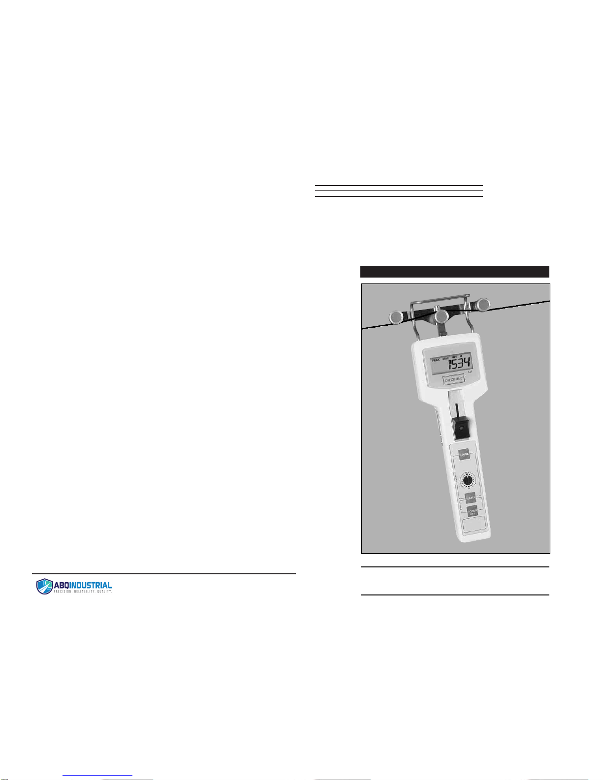
The CHECK•LINE®DTMB Digital Tension Meter is a hand-held device which
accurately measures the running as well as static tensions of a wide variety of
process materials including yarns, fibers, wires, optical fibers, etc. It employs
the "three-roller principle" of tension measurement where the outer two reference rollers are fixed to create a known angle of wrap over the middle sensing
roller. The middle roller is part of a precision strain gauge sensing system
which accurately measures the resulting force on the roller. This value is converted into a highly accurate and repeatable tension value using proprietary
computer calibration formulas which correct for different material diameters,
gravity and other critical parameters. The DTMB is powered by four AA batteries and is supplied in a rugged, die-cast aluminum housing.
The DTMB takes 62 tension measurements per second and displays the average of these measurements over a user-selected interval of 0.5, 1, 2 or 4 seconds, the Display Update Rate. This permits the user to determine the extent
of averaging (or damping) required to "stabilize" the tension readings, making
them much easier to read and eliminating the undesirable "bouncing needle"
condition found on most mechanical tension meters. To set or change the
Display Update Rate, refer to Configuring Dip Switch Settings, Section 5.30.
A built-in memory system is provided which permits storage of the maximum,
minimum and peak values occurring during a measuring interval. These values
can be recalled to the display for viewing.
23
Specifications
Measuring Principle Strain gauge
Measuring Frequency 16 msec (62.5 samples/sec)
Deflection of Sensing Roller (max.) 0.2 mm
Overload Capacity 200% of Full Scale
Temperature Coefficient Zero: less than +0.3% FS/ °C Span: less than +0.01% FS/ °C
Display 4-Digit LCD, 12 mm high
Display Update Rate 0.5, 1.0, 2.0 or 4.0 seconds, dip-switch selectable
Memory System Last, maximum, minimum and peak values
Overrange Indicator Value will blink on/off, then “FFFF”
Field Calibration Adjustment
+
7 steps, 1.5% per step
Battery Type Four (4) 1.5 V AA (included)
Battery Life 20 hours, continuous use
Auto Power Off After 2 minutes of non-use
Roller Material (standard) Hard-coated Aluminum ..
. (optional) Hardened Steel (ST), Ceramic (CE), Plastic (PL)
Maximum Speed (standard) 2000 m/ min ...
. (optional) 5000 m/ min
Housing Die-cast Aluminum
Dimensions 2.95" W x 10.83" H x 1.77" D
(75 x 275 x 45 mm)
Weight (approximate) 1.43 lbs.
(650 g)
Operating Temperature 32 to 132 °F
(0 to 45 °C)
Accessories Included 4 AA batteries and operating instruction guide, all in a fitted,
hard-plastic carrying case
Warranty One year
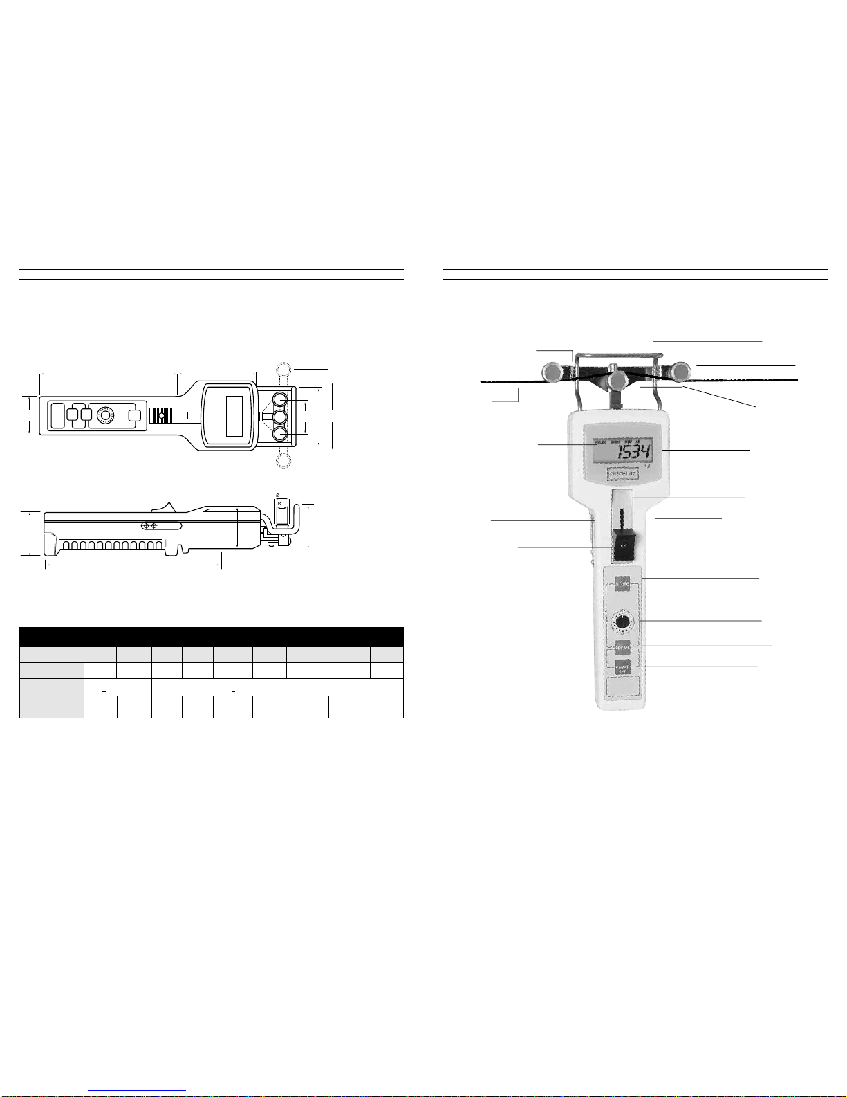
3
Filament Guide
Rollers
LCD Display
Slide Guide Plate
Thickness Compensator
(on back of unit)
Field Calibration
Adjustment
STORE Key
Recall Key
Power/Exit Key
Middle Sensing
Roller
Display Symbols
• MAX
• PEAK
• BATT
• MIN
Filament
Outer Roller Bracket
Sample Holding
Clips
Thumbpiece
2.00 DTMB OVERVIEW
Model DTMB-200 DTMB-500 DTMB-1K DTMB-2K DTMB- 2.5KB DTMB-5KB DTMB-10KB DTMB-20KB DTMB-20KB
Tension Range (grams) 0.1–200.0 0.1– 500.0 50 –1000 200– 2000 250 –2500 500 –5000 1.00– 10.00 Kg 2.00–20.00 Kg 50 KB
Accuracy +
1.0% or better +1.5% or better
Outer Roller Dist. (c:c) 38 mm 38 mm 38 mm 38 mm 100 mm 100 mm 100 mm 200 mm 200 mm
22
10.00 SPECIFICATIONS
37
153 60
38 65 76
Outer roller spacing c:c
2.5KB–10 KB 100 mm
20KB– 50 KB 200 mm
40
192
45
48
15
12
All dimensions in mm
Model Data
4
• Starts/Stops scanning for Max/Min/Peak values. (Standard Memory)
• Starts/Stops automatic recording of values into memory (Continuous Data Logging Model).
• Loads displayed value into memory (On-Demand Data Logging Model).
• Enters Recall Mode to review statistics and recorded Data.
• In recall mode, changes display from LAST ➔ MAX ➔ MIN ➔ PEAK ➔ LAST ➔ MAX etc.
• When in Data Logging Mode: changes display from LAST ➔ MAX ➔ MIN ➔ PEAK.
➔ AVERAGE ➔ STANDARD DEVIATION➔ D ATA # 1➔ D ATA #2 ➔ DATA #3 etc.
• Turns power on.
• Turns power off if pressed and held for 5 or more seconds.
• Exits from Recall Mode when reviewing data.
• Clears all data in Basic Memory (“CCCC” momentarily shown on display).
• Zeros gauge (“Tare”) for use in any orientation (“Gravity Correction”).
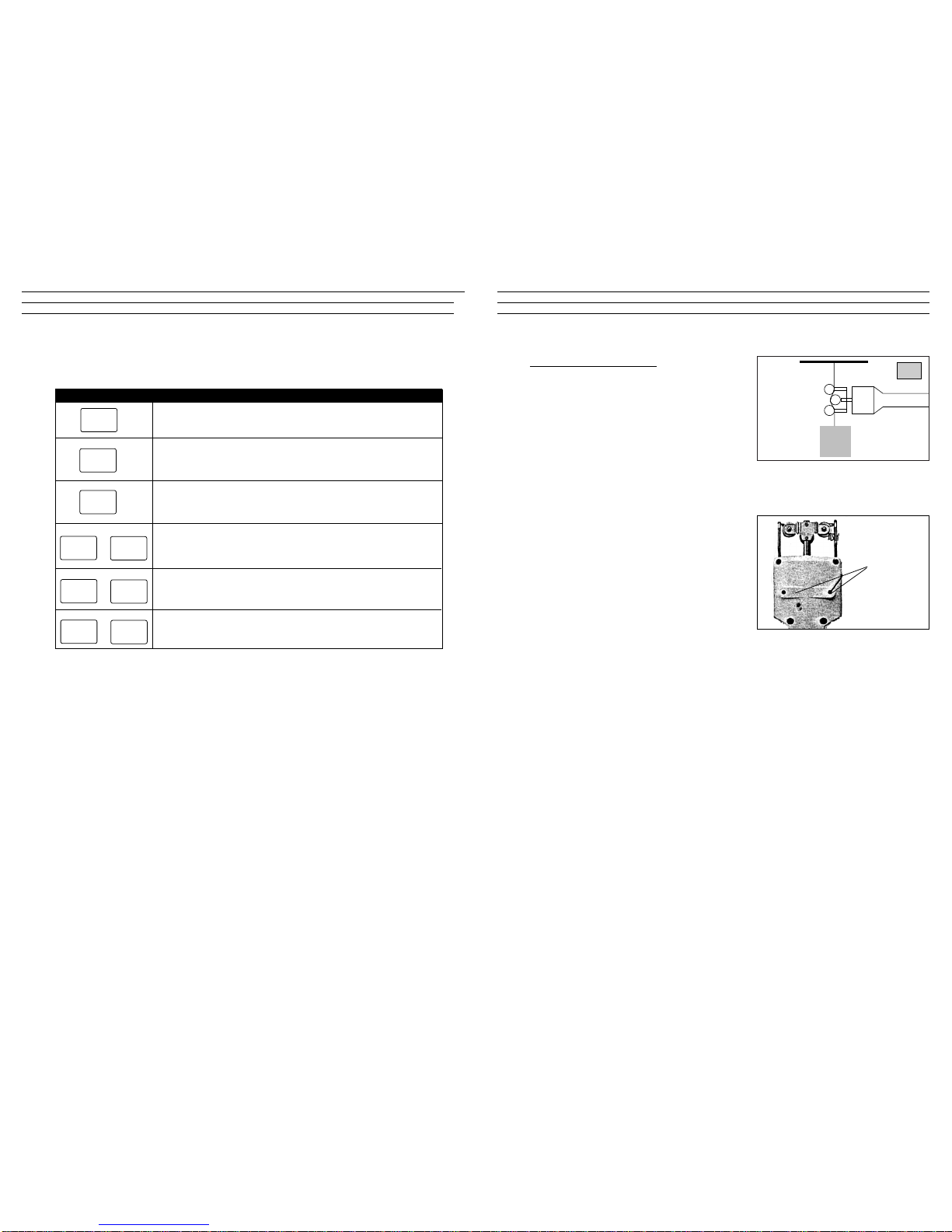
Key Description of Functions
3.00 DESCRIPTION OF MEMBRANE KEY FUNCTIONS
STORE
RECALL
POWER
EXIT
RECALL
STORE
+
POWER
EXIT
RECALL
+
* When the units of measure are changed to grams, the “gf” indicator will
momentarily flash on and then turn off. Otherwise the “lb.” or “oz” indicators
will be shown.
• Changes units of measure from grams (or Kg) to pounds (or ounces) and back again
each time this key combination is pressed.
STORE
POWER
EXIT
+
*
21
8.34 Special Calibration
If the standard Factory Calibration and
the Field Calibration Adjustment does not
provide the desired accuracy, a Special
Calibration can be ordered. A l0' sample
of the process material must be provided
for calibration purposes.
8.40 On-Line Mounting Holes
The DTMB is supplied with two threaded
holes for on-line mounting in a fixed position when performing measurements over
an extended period.
Thread Size M5 (metric)
Thread Depth 7.5 mm (max.)
W
Mounting
holes
SP

5
4.00 QUICK START INSTRUCTIONS
4.10 Setup
1. Insert a sample of the process material into the Thickness Compensator and
secure the ends of the sample under the Sample Holding Clips on each side
of the unit.
Note: Thickness Compensator is not used on the DTMB-200 Model.
2. Set the Field Calibration Adjustment to "STD”
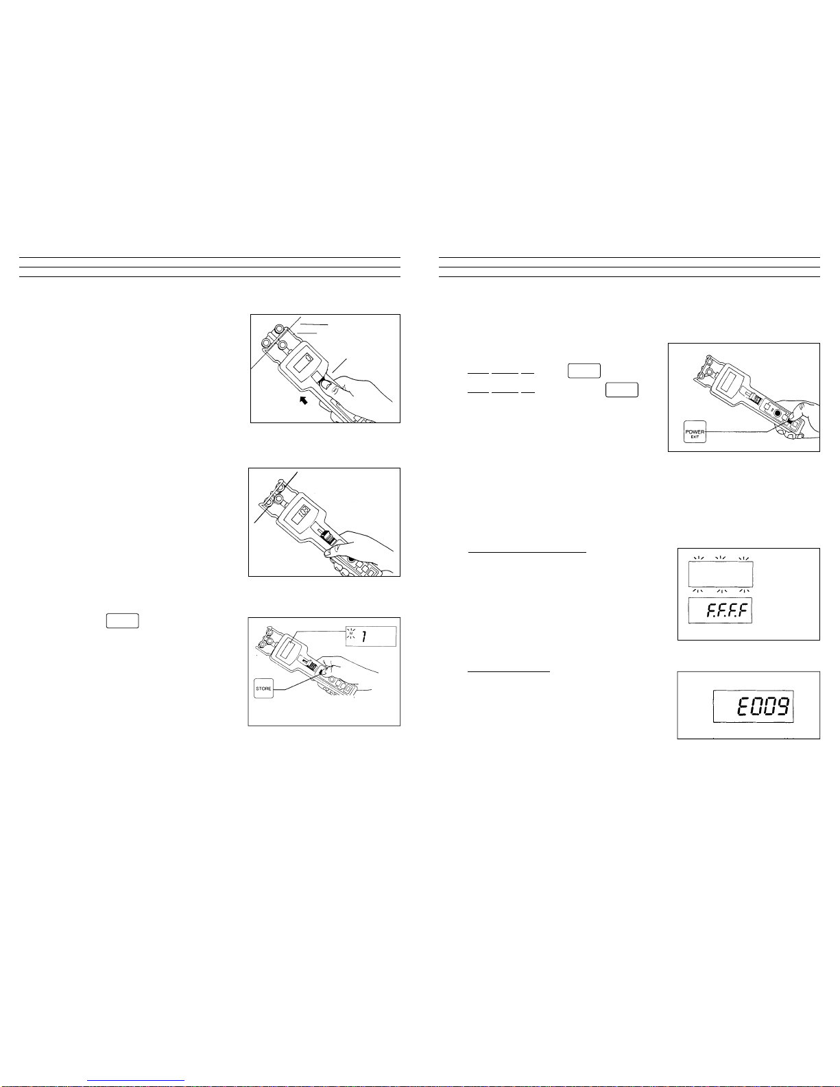
4.20 Operation
1. Turn the unit on by pressing the
key. Display should show zero
when unit is in measuring position. If
the gauge displays zero go to Step 3,
otherwise perform a Gravity Correction
Procedure (Step 2).
2. Position the DTMB into the measuring
position and perform a Gravity
Correction procedure (Zero):
Press the and keys
simultaneously, and hold until the
display shows “0” or “0.0”.
POWER
EXIT
POWER
EXIT
RECALL
20
8.23 Low Battery
When the BATT indicator appears on the
display, the batteries are low. Data will be
lost when the batteries are removed.
8.30 Options
8.31 Ultra-High Speed Roller Assemblies
For line speeds up to 5,000 m/min., specify
“U” roller guides.
8.32 Lever
For high tension ranges, specify an “L”
Lever attachment to make it easier to push
the outer rollers forward for material
acquisition.
8.33 AC Adapter.
Use this adapter during long-term, on-line
measurements to save battery power.
Connects to 115 VAC power sources.
BATTindicator appears on
display.
U
L
AC
6
3. Open the 3-roller system by pushing the
Thumbpiece forward until the outer rollers
extend beyond the Filament Guide.
Position the DTMB so that the process
material contacts the Filament Guide and
passes between the outer rollers and the
middle sensing roller.
4. Release the Thumbpiece SLOWLY until
it returns to its original position. Do
not let it snap back as this could
effect the calibration and damage
the instrument. The display will begin
to show tension readings.
5. Press the key to start and stop
the Measuring Interval.
The M indicator will blink on and off
indicating that the memory is active.
Refer to Built-In Memory, Section 6.00.
STORE
Filament
Filament guide
Thumbpiece
19
8.00 GENERAL NOTES
8.10 Turning Power On/Off
Turn Power On: Press key
T
urn Power Off: Press and the key
for five (5) seconds
Note: DTMB will power off automatically
after 90 seconds of inactivity, except for the
following instances:
• Memory Mode configured for Standard - NAPO (No Auto Power Off)
• When AC Adapter is used
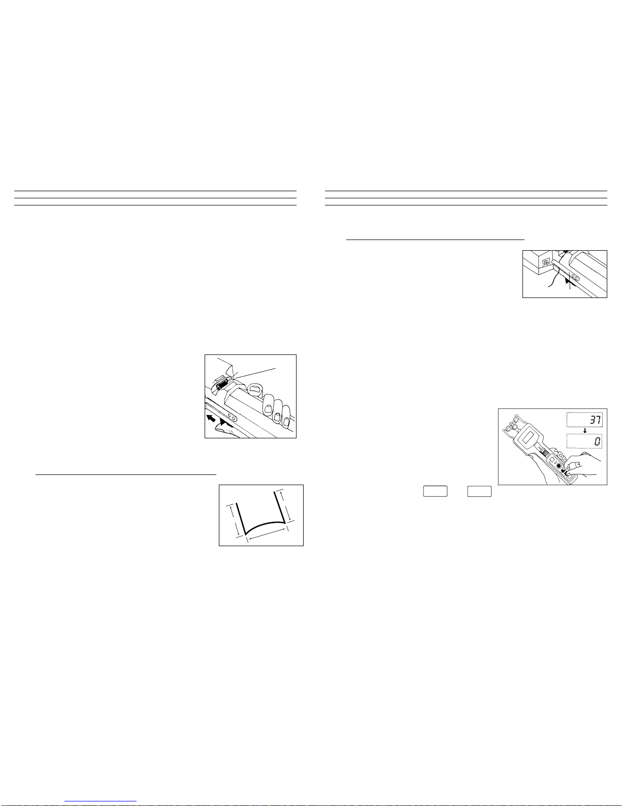
8.20 LCD Display Indications and Codes
.
. 8.21 Over Range Display
When a displayed value is flashing on & off,
this indicates that this reading is higher than
the maximum range of the unit. The accuracy
of the flashing value is not guaranteed. When
all F’s are displayed, this indicates that the
current value greatly exceeds the maximum
range of the unit.
8.22 EProm Error
When this code is displayed, the EProm is
not responding properly. Try turning the
power off and then on again. Try this a few
times. If code will not clear, contact factory.
POWER
EXIT
POWER
EXIT
Flashing
display
values
All “F’s” in
display
“E0009” in display

7
6. Press the key repeatedly to
review the data stored in memory.
Press the key at any time to exit Recall Mode.
The DTMB will automatically power off after 90 seconds of inactivity.
To manually turn off the power, press and hold the key for
5 seconds.
RECALL
MAX
MIN
PEAK
Maximum Value
Last Reading
Minimum Value Peak Value
POWER
EXIT
POWER
EXIT
18
7.20 Field Calibration Adjustment
The Field Calibration Adjustment permits
the end user to "shift" the calibration curve
to provide better accuracy when the Factory
Standard Calibration is not suitable. Each
step on the Field Calibration Adjustment
will increase (clockwise) or decrease
(counterclockwise) the displayed value
by 1.5%.
Increase: [7 steps] x [1 .5% per step] = +10.5%
Decrease: [7 steps] x [1.5% per step] = –10.5%
If a Field Adjustment Calibration is not adequate, the accuracy of the DTMB
can be increased further by ordering a Special Calibration using a calibration
sample supplied by the user. Refer to Special Calibration, Section 7.30.
7.20 LCD Display Indications and Error Codes
7.21 Over Range Display
When a displayed value is flashing on & off, this
indicates that this reading is higher than the
maximum range of the unit. The accuracy of the
flashing value is not guaranteed. When all F’s are
displayed, this indicates that the current value
greatly exceeds the maximum range of the unit.
7.22 Error Codes
If the Error Code “E009” is displayed, try turning
the power on and off a few times to clear it. If it
does not clear, contact the factory. If the Error
Code “E001” is displayed, the user is attempting
to store date with units (g or lb.) different than
those values already stored in memory. Clear the
data stored in memory and start again.
Decrease
1.5%
per step
Increase
1.5%
per step
Factory Calibration
Special Calibration

8
5.00 SETUP
5.10 Installing/Replacing Batteries
1. Using a slotted screwdriver or coin,
loosen the battery cover screw located
at the end of the unit by turning the
screw counterclockwise.
2. Insert four (4) AA , 1.5 volt akaline
batteries into the battery sleeve.
Insert them in the direction indicated
on the top of the sleeve. Use of NiCad
rechargeable batteries is not
recommended.
3. Replace battery cover by first inserting
the tab of the cover into the slot of the
housing and pressing the cover into
place. Tighten the screw by turning it
clockwise.
NOTES:
1. If battery cover will not close, confirm that the batteries are inserted in the
proper orientation. Refer to step 2 above.
2. After replacing the battery, make sure the proper units of measure are
selected.
Battery cover screw
Battery cover
Battery sleeve
Battery
cover
tab
17
7.10 Checking Calibration
It is important to check the calibration of the DTMB
frequently to insure that the gauge continues to
perform within factory specifications. Implementing
a periodic calibration check will help identify when
(and if) the gauge goes out of calibration due to
unreported damage, overload, or other unknown
reason.
To check the calibration:
1. Suspend a known weight “W” from the
process material in either a vertical or
horizontal direction, best simulating the
orientation that will be used during
actual measurement. Fix the process
material at one end.When fixing the
process material horizontally, use a
roller (or other free-rotating guide) prior to fixing the known weight. Refer to
sketches. Select a weight within the expected operating tension range of the
the application
2. Setup DTMB by inserting sample into Thickness Compensator and
performing a Gravity Correction (Zero) if using a horizontal material path.
Refer to QuickStart Instructions, Section 4.0.
3. The DTMB should display a value equal to (or within quoted accuracy
specification) of the known Weight “W”. If not, refer to Field Calibration
Adjustment, Section 7.20.
W
Horizontal Material Path
W
Vertical
Material
Path
Roller
Roller

9
5.20 Using AC-Adapter
The optional AC-DTMX AC Adapter can be
used as an alternative to batteries. Plug one
end of the adapter into an appropriate AC
outlet and the other end into the receptacle
located on the side of the DTMB.
NOTES:
1. When using the AC Adapter, do not remove the batteries as they are used
to save the data in memory when the power is turned off.
2. If the units of measure were changed while the AC Adapter was in use, the
units of measure will revert back to the one’s selected prior to the change.
AC Adaptor receptacle
16
7.00 CALIBRATION
The DTMB is factory calibrated by taking a series of measurements with
known weight standards suspended from Factory Calibration Standard
Materials. The built-in microprocessor uses this calibration data with a complex
formula to calculate a calibration curve which takes into account the material
thickness and orientation of use. The factory calibration works well in most
cases. However, if the process material to be measured differs significantly
from the Factory Calibration Standard Materials (see table below) or if the
application requires the highest accuracy possible, perform a Field Calibration
Adjustment (refer to Section 7.20) or return the gauge to the factory for an
optional Special Calibration.
Note: When ordering a Special Calibration, please supply a 10' sample of the
process material for calibration purposes.
Model Monofilament (mm)
DTMB-200 0.10
DTMB-500 0.10 and 0.20
DTMB-1K 0.20 and 0.40
DTMB-2KB 0.40 and 0.70
DTMB-2.5K 0.40 and 0.70
DTMB-5KB 0.60 and 1.20
DTMB-10KB 0.80 and 1.40
DTMB-20 KB Customer supplied sample
DTMB-50 KB Customer supplied sample

10
5.30 Configuring Dip Switches
The DTMB is supplied with six (6) dip switches permitting the user to select
desired Display Update Rate and Memory Mode as detailed below.
To access the dip switches, the Thumbpiece and Slide Guide Plate must be
removed. Refer to access instructions below.
5.31 Accessing The Dip Switch Block
1. Turn the DTMB power off by pressing and holding the key
for five (5) or more seconds. The display will go blank.
2. Using a small Phillips screwdriver, remove
the screw in the center of the Thumbpiece.
Remove the Thumbpiece and screw. The
Slide Guide Plate and screw will be visible.
3. Using a small Phillips screwdriver, remove
the screw at the bottom of the Slide Guide
Plate and remove plate.
Display Update Rate
Memory Mode
0.5 sec. 1 sec. 2 sec. 4 sec.
Standard Standard-NAPO
= Denotes Factory Setting Standard N A P O = Standard Memory with No Auto Power Off
POWER
EXIT
Slide Guide
Plate
Thumbpiece
15
6.11 Viewing Data in Standard Memory
To view data stored in Standard Memory, press the key.
The following will be displayed when the key is pressed repeatedly.
Each time the key is pressed the displayed value will change.
Press the key at any time to exit the Recall Mode.
6.12 To Clear All Data Stored in the Standard Memory
Press the key and the key simultaneously
6.20 Standard Memory with No Auto Power Off (Standard - NAPO)
This memory mode is identical to the Standard Memory Mode detailed above,
except that when configured in this mode the power will not turn off
automatically after 90 seconds of inactivity.
MAX
MIN
PEAK
Maximum Value
Last Reading
Minimum Value Peak Value
Action Display Will Show LCD Indicator
Press R
ECALL key Maximum Value MAX
Press R
ECALL key Minimum Value MIN
Press R
ECALL key Peak Value PEAK
Press R
ECALL key Last Reading none
RECALL
RECALL
POWER
EXIT
STORE
RECALL

11
4. The Dip Switch Block will be located
at the top of the opening after
removing the Slide Guide Plate.
5.32 Setting Dip Switches
Using a small slotted screwdriver or other pointed tool, slide each of the five (5)
Dip Switches into the ON (up) or OFF (down) position as indicated in the illustration below for the desired setting. Dip Switch #6 is not used.
Memory Mode DIP-5 Data Stored in Memory
Standard Memory OFF MIN, MAX, PEAK
Standard Memory
Without Auto– ON MIN, MAX, PEAK
Power Off
Display Update Rate DIP-1 DIP-2 DIP-3 DIP-4
0.5 sec ON OFF OFF OFF
1.0 sec OFF ON OFF OFF
2.0 sec OFF OFF ON OFF
4.0 sec OFF OFF OFF ON
123456
ON
DIP Switch #6
(Not Used)
Factory switch:
DO NOT
TOUCH
DIP switches
14
6.00 BUILT-IN MEMORY SYSTEM
The DTMB Built-In Memory System can be configured to operate in one of two
modes: Standard Memory or Standard Memory With No Auto Power Off. The
data stored in the Standard Memory can be recalled to the display for viewing.
6.10 Standard Memory Mode
The DTMB takes 62 tension measurements per second and displays the average of these measurements over a user-selected Display Update Rate of 0.5, 1, 2
or 4 seconds. The Standard Memory system checks each displayed value and
retains the Maximum, Minimum and Peak tension values which occurred during the Measuring Interval. The Measuring Interval is started and stopped by
pressing the key.
Maximum V
alue: highest
displayed value during
measuring interval
Minimum
Value: lowest
displayed value during
measuring interval
Peak V
alue: highest transient
valu of all of the measurements used to calculate each displayed value
Note: The “M” indicator on the LCD display will flash on and off, indicating
that the Standard Memory system is activated.
To Start/Stop measuring interval for Standard Memory, press key.
STORE
STORE
1312
5.42 Inserting Sample Into Thickness Compensator
Push the Thumbpiece forward to separate the two
anvils. Insert the sample into the slot and slowly
release the Thumbpiece back to its resting position.
The material sample should be secured between
the two anvils. Place the ends of the sample under
the Sample Holding Clips located on each side of
the unit. If the ends stick up bend them back so they will not present a safety
hazard.
NOTE: In lieu of a sample, an equivalent shim can be inserted into the
Thickness Compensator as long as its compressed thickness is the same as the
process material. The shim should be secured using a spray adhesive on one
side, so it will not fall out each time the Thumbpiece is pushed forward.
5.50 Gravity Correction Procedure (ZERO)
The DTMB is factory calibrated for use in
the right-handed, horizontal position
(vertical material path) with the rollers
aligned vertically. When using the DTMB
in any other orientation, a Gravity
Correction Procedure (Zero) should be
performed.
Hold the instrument in the measuring
position and press the and
keys simultaneously. The display will show zero.
The DTMB is now ready for use.
POWER
EXIT
RECALL
Sample Holding Clip
5.40 Thickness Compensator
When using the "three-roller” principle of tension measurement, an increase in
material diameter will result in an increased tension reading even when the line
tensions are unchanged. The DTMB is supplied with a proprietary Thickness
Compensation system which automatically shifts the outer rollers to compensate
for this effect. Additionally, the Thickness Compensator measures the material
diameter with an accuracy of 0.01 mm (0.0004 ") for use as a factor in the computer calibration formula.
The Thickness Compensator is located on the back of the instrument. When the
Thumbpiece is pushed forward, two metal plates (anvils) will separate creating a
slot for insertion of the material sample.
NOTES:
1. Some monofilaments, wires and other difficultto-bend samples will need special preparation
prior to insertion into the Thickness
Compensator. See Preparing Sample for
Thickness Compensator.
2. It is unnecessary to use the Thickness
Compensator on the DTMB-200 because the
range of material diameters used with this
model is inconsequential.
5.41 Preparing Sample For Thickness Compensator
When using monofilament, wire or other difficultto-bend materials, the sample must be prepared
properly before inserting into the Thickness
Compensator. Using the pliers supplied, bend the
sample as noted in the sketch. For monofilaments,
maintain arc “A” as shown, so sample bends into
anvils.
Thickness Compensator
anvils
1-1/4"
1-1/4"
1-1/2"
arc A
OPERATING MANUAL
Digital
TENSION METER
CHECK•LINE
®
BY ELECTROMATIC
Model DTMB
Distributed by: ABQ Industrial LP USA
Tel: +1 (281) 516-9292 / (888) 275-5772 eFax: +1 (866) 234-0451
Web: https://www.abqindustrial.net E-mail: info@abqindustrial.net
 Loading...