

– 1 –
TABLE OF CONTENTS
01.0 Introduction . . . . . . . . . . . . . . . . . . . . . . . . . . . . . . . . . . . . . . . . . . . . . . . . . . 02
02.0 Setup . . . . . . . . . . . . . . . . . . . . . . . . . . . . . . . . . . . . . . . . . . . . . . . . . . . . . . 02
03.0 Overview . . . . . . . . . . . . . . . . . . . . . . . . . . . . . . . . . . . . . . . . . . . . . . . . . . . . 03
04.0 Operation . . . . . . . . . . . . . . . . . . . . . . . . . . . . . . . . . . . . . . . . . . . . . . . . . . . . 04
4.1 True RPM
4.2 Internal Triggering Mode
4.3 Synchronous Output Signal
4.4 FPM Display Mode
4.5 Deg m/sec Display Mode
05.0 Changing Memory Parameters. . . . . . . . . . . . . . . . . . . . . . . . . . . . . . . . . . . . 07
06.0 Battery Management (DT-315A Only) . . . . . . . . . . . . . . . . . . . . . . . . . . . . . 08
6.1 Charging the Battery
6.2 Replacing the Battery
07.0 Flash Tube Replacement . . . . . . . . . . . . . . . . . . . . . . . . . . . . . . . . . . . . . . . . 09
08.0 Specifications . . . . . . . . . . . . . . . . . . . . . . . . . . . . . . . . . . . . . . . . . . . . . . . . . 10
09.0 Troubleshooting . . . . . . . . . . . . . . . . . . . . . . . . . . . . . . . . . . . . . . . . . . . . . . . 11
10.0 Warranty. . . . . . . . . . . . . . . . . . . . . . . . . . . . . . . . . . . . . . . . . . . . . . . . . . . . . 12
WARNING
1. Do not look at the emitted light for long periods of
time, it can be harmful to the eyes.
2. Do not disassemble or repair the unit while in
operation.
3. Do not operate or store the instrument in the
following places: explosive areas, areas near
water, oil, dust or chemicals, or areas where
the temperature is above 104°F (40 °C).
– 12 –
10.0 WARRANTY
ELECTROMATIC Equipment Co., Inc. (ELECTROMATIC) warrants to the
original purchaser that this product is of merchantable quality and confirms
in kind and quality with the descriptions and specifications thereof. Product
failure or malfunction arising out of any defect in workmanship or material in the
product existing at the time of delivery thereof which manifests itself within one
year from the sale of such product, shall be remedied by repair or replacement of
such product, at ELECTROMATIC’s option, except where unauthorized repair,
disassembly, tampering, abuse or misapplication has taken place, as determined
by ELECTROMATIC. All returns for warranty or non-warranty repairs and/or
replacement must be authorized by ELECTROMATIC, in advance, with all
repacking and shipping expenses to the address below to be borne by the
purchaser.
THE FOREGOING WARRANTY IS IN LIEU OF ALL OTHER WARRANTIES,
EXPRESSED OR IMPLIED, INCLUDING BUT NOT LIMITED TO, THE
WARRANTY OF MERCHANTABILITY AND FITNESS FOR ANY
PARTICULAR PURPOSE OR APPLICATION. ELECTROMATIC SHALL NOT
BE RESPONSIBLE NOR LIABLE FOR ANY CONSEQUENTIAL DAMAGE,
OF ANY KIND OR NATURE, RESULTING FROM THE USE OF SUPPLIED
EQUIPMENT, WHETHER SUCH DAMAGE OCCURS OR IS DISCOVERED
BEFORE, UPON OR AFTER REPLACEMENT OR REPAIR, AND WHETHER
OR NOT SUCH DAMAGE IS CAUSED BY MANUFACTURER’S OR
SUPPLIER’S NEGLIGENCE WITHIN ONE YEAR FROM INVOICE DATE.
Some State jurisdictions or States do not allow the exclusion or limitation of
incidental or consequential damages, so the above limitation may not apply to
you. The duration of any implied warranty, including, without limitation, fitness
for any particular purpose and merchantability with respect to this product, is
limited to the duration of the foregoing warranty. Some states do not allow
limitations on how long an implied warranty lasts but, not withstanding, this
warranty, in the absence of such limitations, shall extend for one year from the
date of invoice.
ELECTROMATIC Equipment Co., Inc.
600 Oakland Ave. Cedarhurst, NY 11516—USA
Tel: 1-800-645-4330/ Tel: 516-295-4300/ Fax: 516-295-4399
Every precaution has been taken in the preparation of this manual. Electromatic Equipment Co., Inc.,
assumes no responsibility for errors or omissions. Neither is any liability assumed for damages resulting
from the use of information contained herein. Any brand or product names mentioned herein are used for
identification purposes only, and are trademarks or registered trademarks of their respective holders.
– 2 –
1.0 INTRODUCTION
Congratulations on your purchase of a Check•Line® DT-311A or DT-315A
stroboscope/digital tachometer.
Please read the entire instruction manual thoroughly before initial set-up and
operation; the information contained herein will aid you in operating your
stroboscope safely and with excellent results.
If upon delivery shipping damage is detected, do not operate the unit. Notify the
shipping carrier immediately for damage claim instructions. Refer to nameplate
and record serial number for future reference.
Items included with the DT-311A/DT-315A are:
• Handle
• Flash tube removing tool
• AC charger/adapter (Model 315A only)
Optional Accessories:
• Carrying Case
2.0 SETUP
The DT-311A and DT-315A may be operated handheld or else mounted on a
tripod for added convenience.
To mount the strobe on a tripod (or any other mounting surface), use screw
1/4 -20unc, length 8mm or shorter for the tripod screwhole on the bottom.
– 11–
9.0 TROUBLESHOOTING
FPM reading is displayed but unit is not flashing:
• Flash tube may need to be replaced.
(see "Flash Tube Replacement" section).
Stroboscope is in external trigger mode, no flash:
• Check flash tube. Replace if necessary.
• Check for damaged wiring and/or loose pin connections.
Stroboscope is in internal trigger mode, no flash:
• Check flash tube. Replace if necessary.
• Check for damaged wiring and/or loose pin connections..
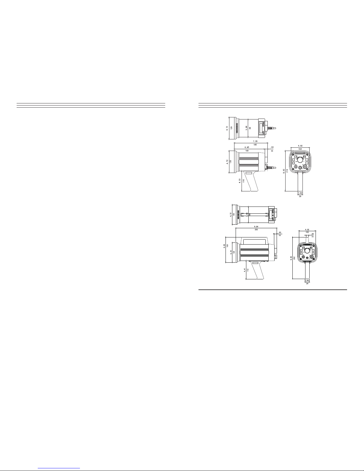
DT-311A
DT-315A
– 3 –
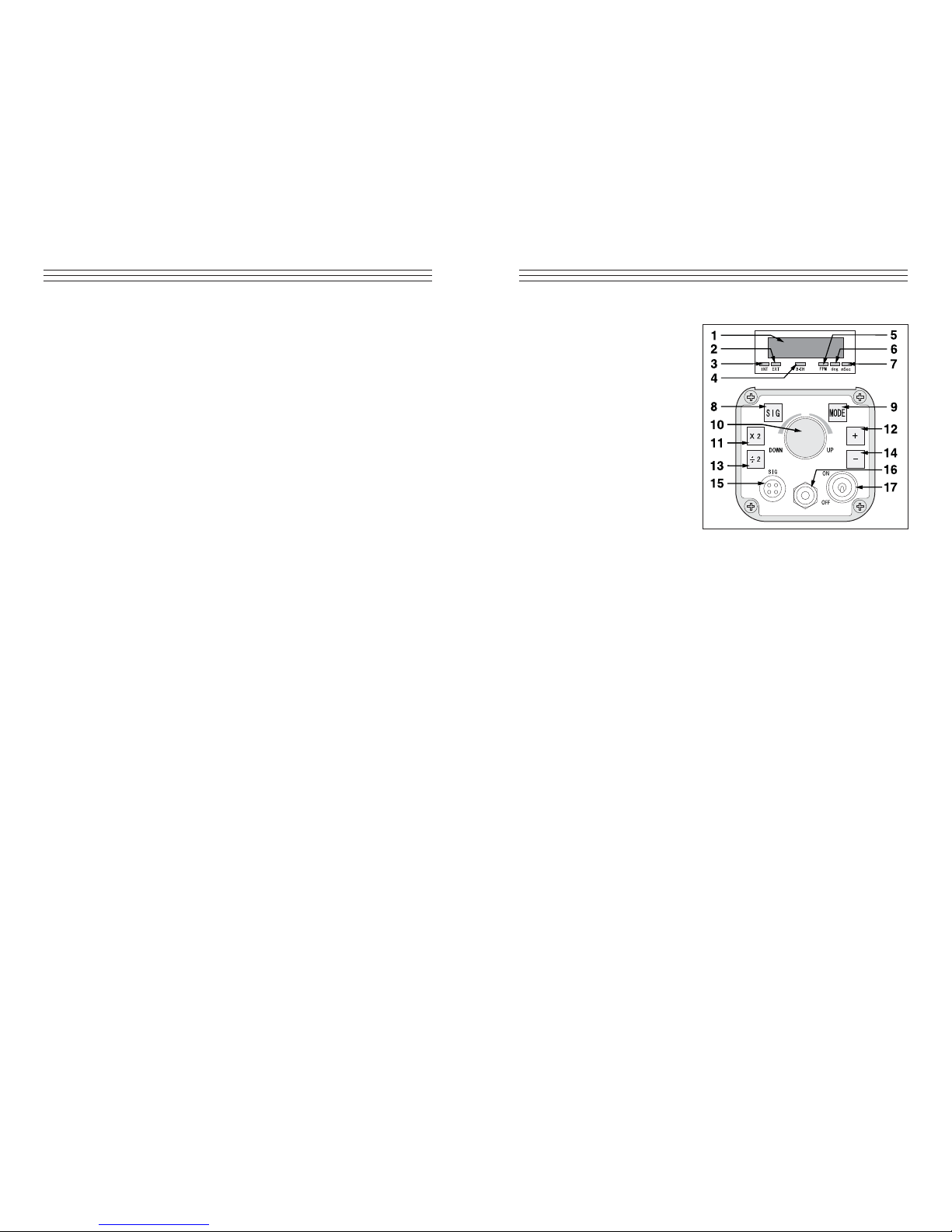
3.0 OVERVIEW
01. LED display: Displays
function and value
02. EXT: External mode
indicator
03. INT: Internal mode indicator
04. B-CH: Battery charge
indicator (DT-315A only)
05. FPM: Flash per minute
indicator
06. deg: Phase shift degree
indicator
07. mSec: Millisecond delay
time indicator
08. Signal switch: Switches
the unit from the external
mode to the internal mode
(and vice-versa)
09. Display mode switch: When unit is set to the externalmode, the strobe
will switch to RPM (FPM)/deg/msec each time “MODE” is depressed
RPM (FPM) Displays flashes per minute. External input 0-35,000 RPM
(FPM)
deg Displays flash delay in degrees
msec Displays flash delay in msec
10. Setter: Changes the flashing rate
11. (x2) Switch: In the internal mode, pressing “x2”doubles the flashing rate
12. (+) Switch: In the internal mode, when object appears to be standing still,
pressing “+” will give the illusion that the object is moving towards the
rotating direction at a speed of 1 rotation in 6 seconds
13. (÷2) Switch: In the internal mode, pressing “÷2” divides the flashing rate
by two
14. (–) Switch: In the internal mode, when object appears to be standing still,
pressing
“
–“ will give the illusion that the object is moving in reverse at a
speed of 1 rotation in 6 seconds
15. Input and output connector:
PIN #1: +12V
PIN #2: Synch output signal
PIN #3: Input signal
PIN #4: 0V
16. Power cord (DT-311A) / AC adapter (DT-315A)
17. Power switch
– 10 –
8.0 SPECIFICATIONS
INTERNAL MODE
Flashing Range 40.0 - 35,000 FPM (flashes per minute)
Accuracy ±0.01% of reading
Resolution 0.1 FPM: 40.0 - 4,999.9 FPM
0.2 FPM: 5,000 - 7,999.8 FPM
0.5 FPM: 8,000 - 9,999.5 FPM
1 FPM: 10,000 - 35,000 FPM
Phase Shift Use +/- push buttons (360° in 6 seconds)
Display Update Time 0.2 sec approx.
Output Signal Synchronous, 400 μsec. Pulse output,
0 to +12 VDC amplitude(approx.), 4.7 Kø impedance
Rate Multiplier/Divider Multiply by 2, divide by 2
EXTERNAL MODE
Flashing Range 0.0 - 35,000 FPM
Accuracy ±0.01% ±1 digit
Phase Shift 0 - 359° with 1° resolution
Delay Time 0 - 2,000 msec from 40 - 10,000 FPM
External Trigger Input Signal LO level: 0 - 0.8 VDC, HI level:
2.5 - 12 VDC or open collector (NPN),
pulse width 50 μsec min.
Input Impedance 4.7 Kø at 12 V / 6.8 Kø at 0 V
GENERAL
Display 5 digits, 0.4" (10 mm) high, LED
Flash Tube Power/Life Xenon, 10 W max. (100 million flashes)
Flash Duration 10 - 40 μsec
Sensor Power Supply 12 VDC (40 mA)
Low Battery Indicator Display shows all L’s
Power Requirement
DT-311A 115 VAC or 220 VAC ±10% 60/50 Hz, 30 VA
(specify voltage)
DT-315A Internal Battery Pack
Operating Temp. Range 32° - 104°F ( 0 - 40°C )
Weight
DT-311A 2.6 lb (1.2 kg)
DT-315A 4.4 lb (2 kg)
Dimensions
DT-311A 7.28"L x 4.72"W x 4.72"H (185 x 120 x 120 mm)
DT-315A 9.84"L x 4.72"W x 4.72"H (250 x 120 x 120 mm)
Warranty 1 year
Standard Accessories Handle, flash tube removal tool Handle, flash tube
removal tool and AC charger/adapter
Optional Accessories Carrying case

– 4 –
4.0 OPERATION
4.1 True RPM Measurement
DT311A/315A stroboscopes are DUAL function instruments that give the
operator the illusion of “stopped motion” where in actuality the equipment
under observation is in a moving state. By adjusting the flash rate,
equipment in motion appears to be standing still. With a slight adjustment,
movement can be viewed in apparent slow motion, which enables the
operator or observer to study the process in action. All DT311A/315A
stroboscopes can measure rotational (RPM) or reciprocating (strokes per
minute) speeds with the same high precision as with an electronic digital
tachometer.
To measure true revolutions per minute (RPM):
1. “Mark” the object to be measured by either visually noting an inherent
distinguishing characteristic (such as a label, scratch, etc.) or physically
marking the object with a small piece of tape, pencil mark, etc.
2. Firmly plug in power cord.
3. Turn power switch on.
4. Turn setter from highest FPM
downward.
5. The true RPM can be noted once
the action appears frozen and the
first single image of the “mark”
appears (see chart below and
accompanying diagram for
further explanation).
6. To verify RPM reading, press
“÷2”; a single image should
appear again.
Rotation of shaft
(rpm)
Number of
flashes (rpm)
Flashes/
rpm shaft
Number of
stopped images
at
1,500 rpm
6,000 4 times 4
4,500 3 times 3
3,000 2 times 2
1,500 1 times 1
750 1/2 times 1
500 1/3 times 1
– 9 –
7.0 FLASH TUBE REPLACEMENT
When FPM reading is displayed but unit is not flashing, flash tube may need to
be replaced:
1. Unplug line cord from power line (DT-315A).
2. Turn power switch off
IMPORTANT: Wait a few minutes until stroboscope is cool before replacing
flash tube.
3. Remove protective window by removing the
4 screws.
4. Use tube removing tool provided: insert tool
all the way and turn clockwise until tool locks.
Pull out tube.
5. Install new flash tube using the removing tool.
IMPORTANT: Do not let the flash tube come in
contact with bare skin, use a rag when handling.
NOTE: Make sure that the tube is placed vertically
in the socket (see diagram below) otherwise it will
touch the reflector. Tube should be set symetrically
within the neck of the reflector.
6. Replace protective window.
7. Mount reflector in the center so that the
reflector will not interfere with the screw spacer
on the corners.

– 5 –
4.2 Internal Triggering Mode
To operate the stroboscope in internal triggering mode:
1. Firmly plug in power cord (DT-311A only).
2. Turn power switch on.
3. If internal indicator is not on, press “SIG”; the INT light
will then turn on.
4. Aim light beam at object under observation. The optimal distance
between the strobe and moving object is approximately 2 feet.
5. Measure RPM by turning the setter to adjust the flashing rate to the
rotational speed of the object.
NOTE: To achieve a particular rate quickly, use the “x2” or “÷2” switches
and then the setter for fine tuning.
NOTE: Once the internal timer has expired, the strobe will stop flashing
and the display will flash rapidly. To restart the strobe, turn power switch
off, then on, and the cycle will repeat
4.3 External Triggering Mode
To operate the stroboscope in external triggering mode:
1. Connect external trigger or sensor wires according to connector pin
designation:
1 +12V (for powering sensor)
2 Synch output signal
3 External input signal
4 0V (common)
2. Firmly plug in power cord.
3. Turn power switch on.
4. If INT lamp is on, press “SIG” until EXT lamp turns on.
5. Press “MODE” to select proper mode:
FPM: Light will flash in correspondence with input signal; the input
signal will be calculated into FPM and displayed.
deg One cycle of input signal is 360°. A delayed angle will be
displayed from 0 up to 359°. (The delayed angle can be changed
by turning the knob setting as previously described).
msec The above delayed
angle will be displayed
in msec.
– 8 –
6.0 BATTERY MANAGEMENT (DT315A ONLY)
Model DT-315A is equipped with an internal rechargeable battery.
NOTE: Charge battery for approx. 15 hrs. before using the instrument
for the first time.
6.1 Changing the battery
If battery is low, “LLLLL” is displayed and display will eventually
disappear. Charge battery as follows:
1. Turn power off.
2. Insert AC adapter/charger plug
into the strobe receptacle
3. B-CH lamp will be lit during
battery charge; within 2 hours
the battery should be charged
completely.
NOTE: The adapter/charger may be used as a power supply to power the
strobe continuously.
6.2 Replacing the Battery
The life of the built-in battery should last for approximately 300 charges.
If the time period between recharges becomes increasingly shorter, then
replace battery with a new one.
Charge the unit with the included
AC adapter/charger only.
AC adapter/charger receptacle

– 6 –
NOTE: If the input signal frequency exceeds upper or lower limits, the
alarm dashes (-----) will be displayed and the strobe will stop flashing.
NOTE: Once the internal timer has expired, the strobe will stop flashing
and the display will flash rapidly. To restart the strobe, turn power switch
off, then on, and the cycle will repeat.
4.4 Synchronous Output Signal
For triggering and controlling additional stroboscopes, the synchronous
output signal appears on pin #2 (see below).
4.5 FPM Display Mode
If the input signal exceeds 585Hz, the upper dashes on the digital display
will be flashing:
----- upper dashes
If the input signal is lower than 0.67Hz, the lower dashes on the digital
display will be flashing:
----- lower dashes
4.6 Deg/msec Display Mode
If the input signal exceeds 167Hz, the upper dashes on the digital display
will be flashing:
(deg) ----- upper dashes ----- (msec)
If the input signal is lower than 0.67Hz, the lower dashes on the digital
isplay will be flashing:
(deg) ----- lower dashes ----- (msec)
If the input signal is lower than 0.67Hz, the lower dashes on the digital
display will be flashing:
(deg) ----- lower dashes ----- (msec)
– 7 –
5.0 CHANGING MEMORY PARAMETERS
The following parameters are set at the factory:
• Decimal point: autorange
• Internal timer: continuous
• External trigger edge: L-H (Lo to Hi)
These parameters can be changed in the field to facilitate different situations.
To change any of the above parameters, follow these steps:
1. Turn power on.
2. Make sure that INT lamp is on. If not, press “SIG” until it turns on.
3. Change the desired memory parameter:
a. To change the decimal point:
• Press “÷2” and “-“ at the same time for approximately 2 seconds until
display alternates between —1— and 0.0.
• Press “+”. The display will freeze and show 0.0.
• Change decimal point accordingly by pressing “+”. If 0.0 is selected
the decimal point is in the autorange mode. If 0 is selected the decimal
point is eliminated throughout the entire range.
b. To change the internal timer:
• Press MODE. The display will alternate between —2— and 0.
• Press “+”. The display will freeze to 0.
• Use the setter to set timer anywhere between 1 and 120 minutes.

Models DT-311A / DT-315A
DIGITAL TACHOMETER/STROBOSCOPE
Operating Instructions
CHECK•LINE
®
BY ELECTROMATIC
Distributed by: ABQ Industrial LP USA
Tel: +1 (281) 516-9292 / (888) 275-5772
eFax: +1 (866) 234-0451
Web: https
://www.abqindustrial.net E-mail: info@abqindustrial.net
 Loading...