

Electromaten TS 959 Installation Instructions Manual
en
Installation instructions
Door control
TS 959
51171547_d_03_2014
0000000 0000 51171547 XXXXX

2
GfA - Gesellschaft für Antriebstechnik GmbH
Wiesenstraße 81
D-40549 Düsseldorf
www.gfa-elektromaten.de
info@gfa-elektromaten.de

3
Table of contents
1 General safety information ............................................................................................ 5
2 Technical data .............................................................................................................. 6
3 Mechanical installation .................................................................................................. 7
4 Electrical installation ..................................................................................................... 8
Cable connection overview ............................................................................................... 9
Limit switch assignment for screwable version until year of manufacture of 1997 .......... 10
Assignment of individual limit switches ........................................................................... 10
Carrying out the electrical installation .............................................................................. 11
Mains connection ............................................................................................................ 12
Mains connection to control ............................................................................................ 12
Completing the electrical installation ............................................................................... 12
Overview of control panel ................................................................................................ 13
5 Initial operation of the control ...................................................................................... 14
DES: Rapid adjustment of final limit positions ................................................................. 14
NES: Rapid adjustment final limit positions ..................................................................... 15
6 Advanced electrical installation.................................................................................... 16
External supply X1 .......................................................................................................... 16
Emergency stop X3 ......................................................................................................... 16
Relay contact X20 ........................................................................................................... 16
Control device X5 ............................................................................................................ 1 6
Spiral cable connection ................................................................................................... 16
7 Programming the control ............................................................................................. 17
8 Table of menus ........................................................................................................... 18
Operating mode .............................................................................................................. 18
Door positions ................................................................................................................. 18
Door functions ................................................................................................................. 19
Safety functions .............................................................................................................. 19
Maintenance cycle counter ............................................................................................. 20
Reading out memory ....................................................................................................... 21
Delete all settings ............................................................................................................ 21
9 Safety devices ............................................................................................................ 22
X2: Input, door safety switch ........................................................................................... 22
X3: Input, emergency stop .............................................................................................. 22
4
10 Functional description ................................................................................................. 23
X1: Mains supply line for control and external supply ..................................................... 23
X5: Input, control device .................................................................................................. 24
Advanced hold-to-run function ........................................................................................ 24
X20: Floating relay contact .............................................................................................. 25
Force monitoring (DES only) ........................................................................................... 25
Travel time monitoring (NES only)................................................................................... 26
Maintenance cycle counter .............................................................................................. 27
Short-circuit/Overload display ......................................................................................... 27
Standby function ............................................................................................................. 2 7
11 Status display ............................................................................................................. 28
12 Explanation of symbols ............................................................................................... 32
13 Declaration of Incorporation/Declaration of Conformity ................................................ 34
Symbols
Warning - Risk of injury or danger to life!
Warning - Danger to life through electrical current!
Note - Important information!
▶
Request - Required action!
Illustrations show example products. Deviations from the delivered product are possible.

5
1 General safety information
Specified normal use
The door control is intended for a power-operated door with a drive unit.
The safe operation is only guaranteed with normal specified use. The drive unit is to be
protected from rain, moisture and aggressive ambient conditions. No liability for damage
caused by other applications or non-observance of the information in the manual.
Modifications are only permitted with the agreement of the manufacturer. Otherwise the
Manufacturer’s Declaration shall be rendered null and void.
Safety information
Installation and initial operation tasks are to be performed by trained, skilled fitters only.
Only trained electrical craftsmen are permitted to work on electrical equipment. They must
assess the tasks assigned to them, recognise potential danger zones and be able to take
appropriate safety measures.
Installation work is only to be carried out with the supply off.
Observe the applicable regulations and standards.
Coverings and safety devices
Do not operate unless corresponding coverings and safety devices are fitted/installed.
Ensure that gaskets are correctly positioned and cable glands are correctly tightened.
Spare parts
Use only original spare parts.

6
2 Technical data
Series TS 959
Dimensions W x H x D 155 x 386 x 90 mm
Assembly vertical
Vibration
Assembly
free of vibration
Operating frequency 50/60 Hz
Supply voltage (+/- 10%)
1 N~220 V, PE
3 N~220-400 V, PE
3~220-400 V, PE
Output power for drive unit, maximum 3 kW
Backup fuse per phase, on-site 10-16 A
External mains supply: X1/L, X1/N
(backup fuse via F1 micro-fuse)
1 N~230 V
1.6
A
time-
la
g
Control inputs
24 V DC
type 10 mA
Type relay contact
Max. current of 1A at 230VAC, and 0.4A at 24VDC
(The use of LED lamps is recommended.)
floating changeover
contacts
Loading of relay contacts,
ohmic/inductive
230 V AC
1 A
Control power consumption 10 VA
Temperature range
Operation: -5..+40
Storage: +0..+50
°C
Humidity
up to 93 %
non-condensing
Class of protection of housing IP54
Compatible GfA limit switch NES; DES
7
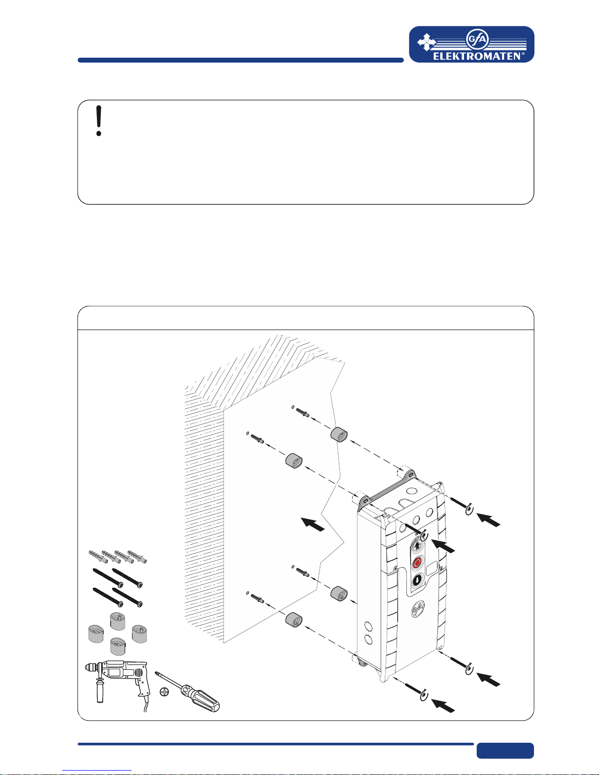
3 Mechanical installation
Control installation!
Only use indoors
Mounting only on a level ground free of vibration
Only vertical mounting position permissible
Door must be visible from the assembly site
Prerequisites
The permissible loads of walls, mountings, connecting and transmission elements must not
be exceeded.
Mounting
The control is mounted via 4 elongated holes
8
4 Electrical installation
Warning - Risk of electrocution!
Disconnect the cables and check that they are de-energised
Observe the applicable regulations and standards
Make a proper electrical connection
Use suitable tools
On-site backup fuse and disconnector unit!
Connection to the indoor installation via all-pole disconnector unit ≥ 10 A as per
EN 12453 (e.g. CEE plug connector, main switch)
Read the drive installation instructions!
9
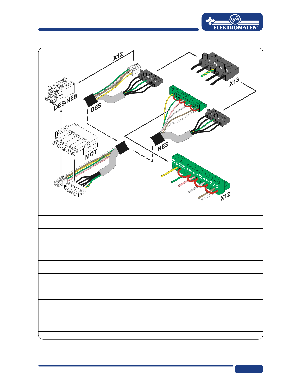
Cable connection overview
DES and NES
motor connection cable
DES connection cable for limit switch
MOT X13
Motor plug
DES X12 Limit switch plug
Pin Core Term. Pin Core Term.
1 3 W Phase W 1 5/wh 1 +24 V safety circuit
2 2 V Phase V 2 6/bn 2 Channel B (RS485)
3 1 U Phase U 3 7/gn 3 Earth
4 4 N Neutral conductor (N) 4 8/ye 4 Channel A (RS485)
5 PE PE 5 9/gy 5 Safety circuit
6 10/pk 6 8-VDC mains supply
Cam-limit connecting cable
NES X12 Limit switch plug
Pin Core Term.
1 5/wh 11 Limit switch potential +24 V, jumper on X12 5, 7, 9, 11, 14
2 6/bn 12 S5 additional limit switch, testing or safety edge function
3 7/gn 6 S3, “Open” limit switch
4 8/ye 15 S6 additional limit switch, relay function
5 9/gy 8 S4, “Close” limit switch
6 10/pk 4 Safety circuit
10
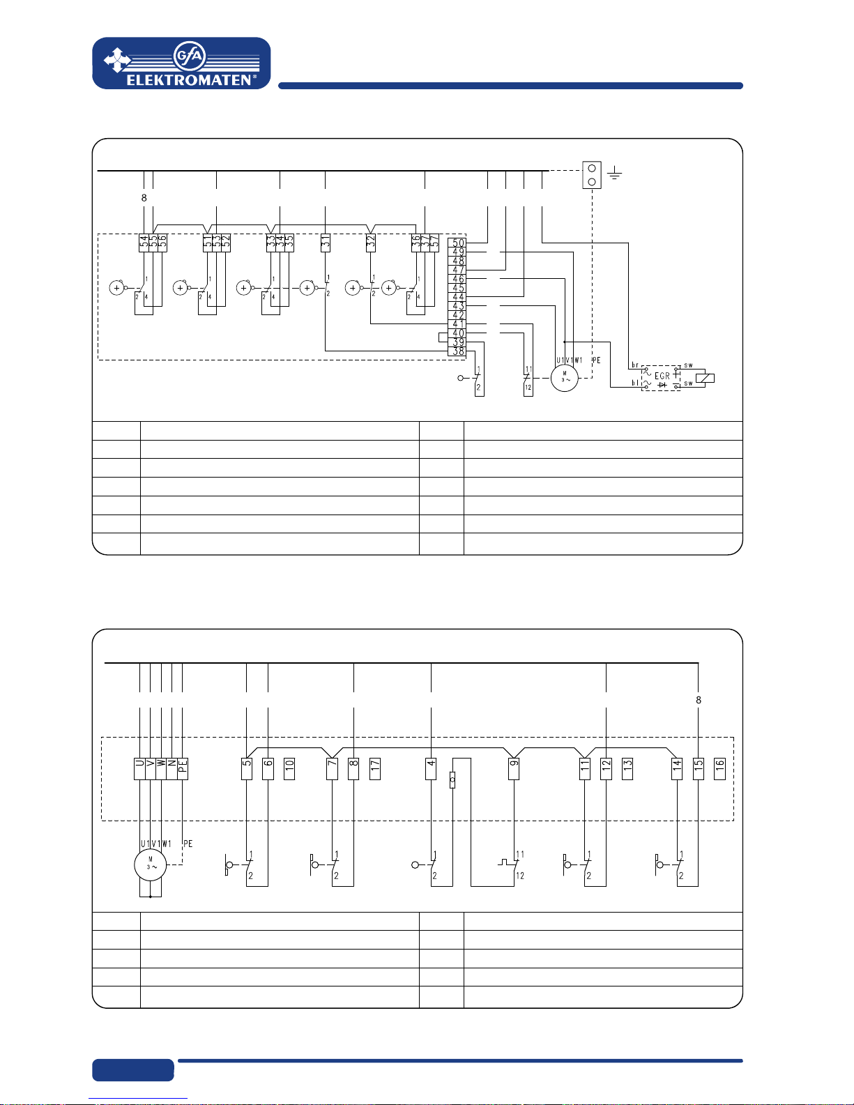
Limit switch assignment for screwable version until year of manufacture of 1997
F1 Thermal contact X12 Limit switch board
G1 Rectifier S1 Emergency open limit switch
M1 Motor S2 Emergency close limit switch
S10 Emergency manual operation S3 Open limit switch
W1 Connection cable S4 Close limit switch
Y1 Spring-loaded brake S5
A
uxiliary limit switch
S6
A
uxiliary limit switch
Assignment of individual limit switches
A
1 Terminal box S3 Open limit switch
F1 Thermal contact S4 Close limit switch
M1 Motor S5
A
uxiliary limit switch
S10 Emergency manual operation S6
A
uxiliary limit switch
W1 Connection cable
5
6710 93214(N)
S6 S5 S3 S1 S2 S4
S10 F1
G1
Y1
1
3
2
4
5
X12
W1
M1
5 671093214PE
M1 S10 F1S4S3 S5 S6
W1
A1
11
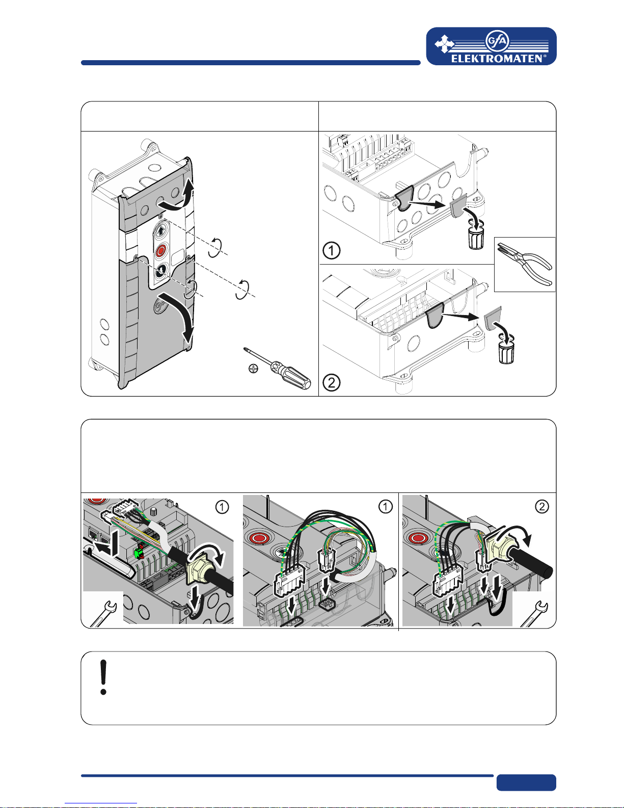
Carrying out the electrical installation
▶ Remove coverings. ▶ Open cable entry ① or ②.
▶ Insert and connect control – drive connection cable in the open cable entry ① (from
below) or ② (from above).
▶ Tighten cable gland.
Caution – Damage of components!
Open cable conduit with suitable tool
Install cable entries and/or cable glands
 Loading...