

ElectroMaax AQUAMAAX MODULAR SERIES Installation, Operation & Maintanance Instructions
AQUAMAAX MODULAR SERIES
WATERMAKER
Installation, Operation &
Maintenance Manual
ElectroMaax
6391 Walmore Road
Niagara Falls, New York, 14304 USA
Toll Free: 1-866-945-8801
Fax: 1-905-945-8802
On the Web: www.electromaax.com
Email: sales@electromaax.com
1

Table of Contents
Introduction……………………………………………………………………………………………..4
AquaMaax Warranty……………………………………………………………………………………4
General Cautions and Warnings…………………………………………………………………………5
General Cautions and Warnings (cont.)…………………………………………………………………6
Tubing and Fitting Installation and Design Philosophy…………………………………………………7
Low Pressure Fittings ........................................................................................................................... 7
Figure 1: Fitting, Locking Clip & Tubing Installation ...................................................................... 7
RECOMMENDED MAINTENANCE…………………………………………………………………7
Tubing Removal from Fittings .............................................................................................................. 7
Figure 2: Tubing Removal Assist Tool for ¼”, and ½” Tubing ....................................................... 8
Tubing Color Coding ............................................................................................................................ 8
Figure 3: Tubing Colors, Sizing, and Pressure Ratings .................................................................... 9
Tubing Cutter ........................................................................................................................................ 9
Figure 4: Tubing Cutter ..................................................................................................................... 9
AquaMaax Specifications……………………………………………………………………………...10
Production Rate:.................................................................................................................................. 10
Product Water Total Dissolved Solids (TDS) range: .......................................................................... 10
RO Membrane: .................................................................................................................................... 10
Electrical Power Requirements for AC and DC Models: ................................................................... 11
High Pressure Sea Water Pump AC Model ......................................................................................... 11
Electric Motor AC Model ................................................................................................................... 11
Electric Motor DC Model ................................................................................................................... 11
Sea Water 12 VDC Boost Pump: ........................................................................................................ 12
High Pressure RO Membrane housings: ............................................................................................. 12
Pre-filter and Backwash Filter housings: ............................................................................................ 12
Figure 5: Process Flow Diagram ..................................................................................................... 13
Installation Instructions………………………………………………………………………………...14
Figure 6: Pump and AC Motor ....................................................................................................... 15
High Pressure Pump and Motor Assembly ......................................................................................... 15
Dual RO Pressure Vessels & Membranes with Control Panel Setup ................................................. 17
2

Figure 7: End View of Dual Membrane Assembly ......................................................................... 17
Control Panel…………………………………………………………………………………………...18
Figure 8: Control Panel Front View ................................................................................................ 18
Control Panel
Figure 9
Backside
: Control
..................................................................................................................... 19
Panel Back View ................................................................................................ 19
RO Pressure Vessel ............................................................................................................................. 20
Control Panel Standard Option ........................................................................................................... 20
Pre-filter A
Figure 10
ssembly
............................................................................................................................ 21
: Pre-filter
Assembly20 micron
& 5 Micron
................................................................. 21
Boost Pump ......................................................................................................................................... 22
Figure 11: Boost Pump .................................................................................................................... 22
Valving and Cleaning Assembly ......................................................................................................... 23
Figure 12: Valving and Cleaning Assembly ....................................................................................... 23
Figure 13: 115 VAC Motor Wiring Installation Diagram............................................................... 24
Figure 14: DC Motor Boost Pump Wiring Installation Diagram .................................................... 25
Figure 15: DC Motor Electrical System Schematic ........................................................................ 26
Figure 16: Engine Driven Electrical System Schematic ................................................................. 27
Initial AquaMaax Commissioning Procedure ………………………………………………………….28
Normal Operation Procedure…………………………………………………………………………..30
Normal Shut-down Procedure ………………………………………………………………………….30
Freshwater-flush Procedure…………………………………………………………………………….31
Membrane Cleaning Procedures……………………………………………………………………….32
Pickling and preparing for Long-Term Storage………………………………………………………..34
Return Unit to Normal Operation……………………………………………………………………...34
Installation of the Optional Automatic Flush and solenoid…………………………………………...35
Shutting the system down on models with Auto Flush system……………………………………..…36
Shutting the system down with auto flush system for Extended Period………………………….…..36
Auto Flush Wiring Connections…………………………………………………………………….…37
3

Introduction
The team at ElectroMaax thanks you for your purchase of the AquaMaax reverse osmosis
watermaker. The AquaMaax design is based on real world product testing and
engineering, and we trust that you will be completely satisfied with your new unit. We are
ready to stand behind our product with an industry leading warranty and customer support.
We will assist you in your installation, start-up, and operation of your AquaMaax
watermaker.
The AquaMaax series of water makers were designed with real life cruisers in mind, so the
system is designed for easy installation, operation, and maintenance. We strongly
encourage our customers to spend time reading through our installation, operation and
maintenance manual before starting their installation process and contacting us via email,
for support if they have any questions about their particular installation or general
operation of their new watermaker. Spending some time talking to the people that actually
designed and built your watermaker can quickly help answer any question, from
installation to operation.
AquaMaax Warranty
Due to our simple design and use of commercial quality parts and assembly methods,
ElectroMaax is proud to offer the best warranty in the watermaker business.
The AquaMaax is guaranteed to be free of manufacturer defects and to perform within the
stated specification for a period of three years (36 months) from the date of shipment.
In the event of a defective component or failure during the term of the warranty,
ElectroMaax will inspect the defective part and repair or replace, with all the shipping
charges being the responsibility of the purchaser to and from their location to our offices.
As a condition of the warranty, the purchaser is responsible for conducting the
recommended maintenance according to the ElectroMaax stated schedule of maintenance
and operating their unit within the operational parameters outlined in this manual.
The warranty does not extend to parts that have failed due to misuse, improper installation,
modification, and operations outside of those defined by ElectroMaax.
The warranty does not cover parts where the serial number has been removed or defaced
and the warranty does not apply to the normally recurring consumable or wear and tear
items as defined below:
Pre-filter elements 5 and 20 micron.
Activated, carbon back-flush filter element.
High pressure pump crankcase lubrication oil.
Boost pump flexible impeller.
High Pressure Pump Valves, Packing, and Ceramic Plungers.
4
ElectroMaax’s liability under this warranty shall be limited to repair or replacement of the
ElectroMaax watermaker at ElectroMaax’s option. Under no circumstances shall
ElectroMaax be liable for consequential damages arising out of or in any way connected
with the failure of the system to perform as set forth herein.
General Cautions and Warnings
There are several things which the installer or operator of the AquaMaax can do
incorrectly, which can seriously damage the AquaMaax water maker, dramatically shorten
the operational life span of the system, and in some cases cause personal injury. Knowing
the things to avoid is critical to a good AquaMaax installation and operation. We will
cover the following items again in greater detail during the appropriate section later in the
manual, however, due to their importance it is worth giving the following items extra
attention.
CAUTION
NEVER ALLOW CHLORINATED WATER TO COME IN CONTACT WITH
THE RO MEMBRANES, OXIDANTS SUCH AS CHLORINE AND/OR
BLEACH WATER WILL PERMANENTLY DESTROY THE RO MEMBRANE.
NEVER RUN THE AQUAMAAX IN OILY WATER, AS OIL WILL
PERMANENTLY DESTROY THE RO MEMBRANE.
WARNING
CAUTION
NEVER RUN THE HIGH PRESSURE PUMP DRY OR OPERATE OUTSIDE
THE INLET SUPPLY PRESSURE AND FLOW DESIGN PARAMETERS.
IN BRACKISH WATER, SUCH AS IN AN ESTUARY OR RIVER, NEVER
ALLOW THE PRODUCT WATER PRODUCTION FLOW RATE TO EXCEED
THE UNITS RATED OUTPUT. IN SUCH CASES, SIMPLY TURN DOWN THE
SYSTEM PRESSURE OR RO MEMBRANE DAMAGE WILL OCCUR.
NEVER EXCEED A SYSTEM OPERATIONAL PRESSURE OF 1000 PSI.
DO NOT INSTALL THE RO MEMBRANE MODULE IN AN AREA WHERE
THE RO MEMBRANES CAN BECOME HEAT SOAKED TO TEMPERATURES
ABOVE 120°F WHILE IN OPERATION AND 140°F WHILE NOT IN
OPERATION, DOING SO WILL COOK AND DESTROY THE RO
MEMBRANE.
5
General Cautions and Warnings (cont.)
WARNING
THE HIGH PRESSURE PUMP IS SHIPPED WITH AN OIL PLUG CAP
INSTALLED TO PREVENT CRANKCASE OIL SPILLAGE, BEFORE INITIAL
OPERATION OF THE HIGH PRESSURE PUMP, REPLACE THE PLUG CAP
WITH THE SUPPLIED VENTED CAP.
THE RO MEMBRANE MODULE IS SHIPPED CONTAINING A
STORAGE/PRESERVATIVE SOLUTION; ALLOW A MINIMUM OF 30
MINUTES OF INITIAL OPERATION BEFORE SAMPLING THE PRODUCT
WATER IN ORDER TO PROPERLY FLUSH OUT THE PRESERVATIVE.
THE HIGH PRESSURE PUMP IS CAPABLE OF CREATING A STREAM OF
PRESSURIZED SEA WATER UP TO 1500 PSI. UNDER NO
CIRCUMSTANCES SHOULD THE HIGH PRESSURE PUMP BE OPERATED
WITHOUT THE SUPPLIED PRESSURE RELIEF VALVE IN PLACE OR WITH
THE HIGH PRESSURE LINES NOT PROPERLY CONNECTED.
CAUTION
WHILE PERFORMING A SYSTEM FRESHWATER RINSE, BE SURE THAT
THE PRESSURE REGULATING VALVE IS IN THE COMPLETELY OPEN
POSITION, WHICH CAN BE VERIFIED BY TURNING THE PRESSURE
REGULATING VALVE COUNTERCLOCKWISE UNTIL IT PHYSICALLY
STOPS. RUNNING FRESH WATER OR BRACKISH WATER AT ELEVATED
PRESSURES THROUGH THE RO MEMBRANES WILL PERMANENTLY
DESTROY THE MEMBRANE.
WARNING
A HIGH PRESSURE PUMP AND MOTOR ASSEMBLY ELECTRICAL
CONNECTION IS MANDATORY FOR SAFE SYSTEM OPERATION. DO NOT
INSTALL THE HIGH PRESSURE PUMP AND MOTOR ASSEMBLY IN A
LOCATION THAT WILL BE AT RISK OF EXPOSURE TO SEA OR FRESH
WATER.
6
Tubing and Fitting Installation and Design Philosophy
Low Pressure Fittings
All low pressure fittings are “Push-to-Connect”, high grade, double “O” ring, NSF 58
certified, lead free, polypropylene G.A. Murdock fittings. The AquaMaax system comes
with the push-to-connect fittings pre-installed on all components. Additional fittings are
supplied for ease of installation as there maybe situations where one might need a 90 degree
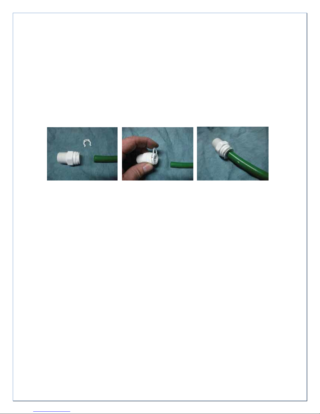
fitting or an additional union to route tubing for a cleaner installation. The photos below
show the “Push-to-Connect fitting, locking clip, and tubing.
Figure 1: Fitting, Locking Clip & Tubing Installation
The locking clip is installed as shown in the middle photo. The locking clip goes between
the fitting body and collet retaining ring. The tubing is then pushed into the fitting until the
tubing seats into the internal stop of the fitting. The tubing cannot be pulled out while the
locking clip is in place.
RECOMMENDED MAINTENANCE
It is recommended that tubing installations are inspected at least annually and parts
replaced as needed.
Tubing Removal from Fittings
To remove the tubing from the fitting the locking clip must be removed. Using the tubing
removal assist tool, press the proper size opening against the collet of the fitting and while
holding the collet up against the fitting securely, pull on the tube until it is removed from
the fitting housing.
7
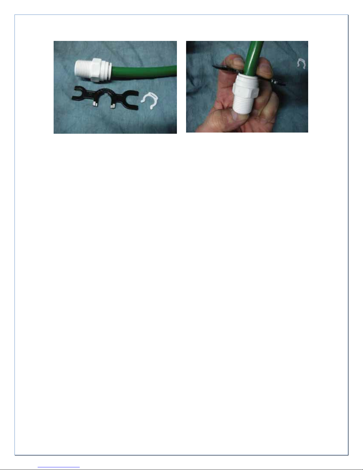
Figure 2: Tubing Removal Assist Tool for ¼”, and ½” Tubing
Tubing Color Coding
The low pressure (pressures listed on chart pg.9) tubing has been color coded depending
upon where it is used in the system. All plastic tubing is linear low density polyethylene
tubing (LLDPE) approved for drinking water use.
Green ½” tubing is used for the raw water plumbing from the ship’s sea strainer, to the
Valving and Cleaning Assembly, to the pre-filters, to the high pressure pump, and also for
discharge from the panels’ “Pressure Regulating Valve”.
Blue ¼” tubing is used for the fresh water product discharge from the RO membrane
assembly which is connected to the inlet of the flow meter on the system control panel. The
three-way Product Water Selector valve on the control panel has two outlets. The outlet
marked “Water Tank” uses ¼” blue tubing is plumbed to the ship’s fresh water drinking
tank. Additionally, the position marked “Water Sample” on the Product Water Selector
valve is plumbed to a sample location using ¼” blue tubing. (Used for the sea water (or
brine) discharging from the High Pressure Relief valve and is discharged over board, via an
above waterline through hull)
8

OD
PSI
F°
1/4"
230 @ 70
120 @ 150
1/2"
150 @ 70
90 @ 150
Figure 3: Tubing Colors, Sizing, and Pressure Ratings
Tubing Cutter
A tubing cutter is supplied with every AquaMaax system. This cutter allows the tubing to
be cut squarely to allow for a leak free seal on every “Push-to-Connect” fitting. The
following photos show the correct placement of the tubing into the tubing cutter. The cutter
has a hinge on one end and once the tubing is placed in the cradle the ends are squeezed
together to cut the tubing.
Figure 4: Tubing Cutter
9

AquaMaax Specifications
Production Rate:
Product water production and Reverse Osmosis (RO) performance varies with pressure,
salinity, and sea water inlet temperature, mainly as a function of kinetics. Warmer water
molecules are moving at a faster rate than cooler molecules and this increased motion leads
to a greater number of water molecules moving through the reverse osmosis membrane.
The rated performance of the AquaMaax was determined in the Bay of Islands, New
Zealand with a sea water temperature of 68° F, a sea water TDS of 33,200 parts per million,
and a system operating pressure of 850PSI. As stated in Dow Chemical’s Filmtec RO
Membrane specification, product water production can vary by up to +/- 20% of the rated
flow rate for individual elements.
Product Water Total Dissolved Solids (TDS) range:
The presence of dissolved solids in water may affect its taste. The palatability of drinking
water has been rated by panels of asters in relation to its TDS level as follows: excellent,
less than 300 mg/liter; good, between 300 and 600 mg/liter; fair, between 600 and 900
mg/liter; poor between 900 and 1200 mg/liter; unacceptable, greater than 1200 mg/liter.
Water with extremely low concentrations of TDS may also be unacceptable because of its
flat, insipid taste.
http://www.who.int/water_sanitation_health/dwq/chemicals/tds.pdf
RO Membrane:
The AquaMaax watermaker is equipped with DOW Filmtec® RO Membrane(s)
Membrane Type: Polyamide Thin-Film Composite
Part No: SW30
Range of Operating Pressures: 700 to 900 psig
Normal Operating Pressure: 850 psig
Salt Rejection rate: 99.4%
Maximum Flow Rate: 6 GPM
Maximum Operating Temperature: 113°F (45°C)
Minimum Storage/Operating Temp: 32°F (0°C)
Maximum Operating Pressure: 1,000 psi, (69 bar)
Maximum Pressure Drop: 15 psi
pH Range, Continuous Operation: 2-11
pH Range, short-term cleaning:
Free Chlorine Tolerance: <0.1ppm
1-12
10

Electrical Power Requirements for AC and DC Models:
8.4 -19.8 amps @ 115 VAC
4.2 – 9.9 amps @ 230 VAC
2 amps @ 12 VDC for the sea water boost pump
High Pressure Sea Water Pump AC Model
A General Pump Company high pressure triplex plunger pump with a 316 stainless steel
manifold and wetted parts, solid ceramic plungers and an anodized aluminum crankcase.
Maximum Flow rate: Model Dependent
Maximum Inlet pressure:
Maximum Inlet Vacuum: -5 psi
Maximum Discharge Pressure: 1500 psi
Maximum water temperature:
Operating RPM: 1750 RPM
Pump Dimensions: 9” x 7.5” x 6.0”
Crankcase Oil Capacity:
Relief Valve: Preset to crack at 950 psi
up to 50 psi
140°F
12.0 oz (.35L)
Electric Motor AC Model
TEFC sealed motor mechanically coupled to the high pressure pump.
Hz: 60/50
RPM: 1725/1450
Volts: dual 115 VAC / 208 - 230
HP / KW: 1-2.5 / 0.8-2.2
Max amp @ 115 / 208 - 230 VAC: 8.4 amps – 19.8 / 4.2 -9.9amps
Recommended fuse / breaker size: 30 amps (115 VAC)
Use Only a Two-Pole breaker size: 15 amps (208 - 230 VAC)
Electric Motor DC Model
TEFC sealed motor mechanically coupled to the high pressure pump
RPM: 1725
Volts: 12 VDC
Solenoid 200 amp continuous duty
Recommended fuse/breaker size 50 amps
11

Sea Water 12 VDC Boost Pump:
Motor: Permanent magnet type, fully enclosed,
Stainless steel shaft
Pump Body: Thermo plastic
Impeller: Thermo Plastic
Seal Type: Mechanical seal
Typical Amp Draw: 1.6 amps
Recommended fuse size: 5 amps
High Pressure RO Membrane housings:
Filament wound fiberglass/epoxy compound with non-metallic wetted surfaces
Max pressure 1000 psi
Normal operating pressure 850 psi
Pre-filter and Backwash Filter housings:
Industry standard, 10 inch clear, plastic, filter housings. Accepting 9.75” by 2.5”
filter elements.
12
 Loading...