

Page 1

Trademark
R
Please do not return unit to retailer.
Por favor, no devuelva el aparato al lugar de compra.
Veuillez ne pas retourner l’outil au détaillant.
1-800-554-6723
www.weedeater.com
Instruction Manual
Manual de Instrucciones
Manuel d’Instructions
WT3100
ENGLISH ESPAÑOL
For Occasional Use Only
WARNING:
Read and follow all Safety Rules and Operating Instructions before
using this product. Failure to do so can result in serious injury.
ADVERTENCIA:
Lea el manual de instrucciones y siga todas las advertencias e
instrucciones de seguridad. El no hacerlo puede resultar en lesiones graves.
A VERTISSEMENT:
Lirelemanueld’instructions etbienrespecter tous lesavertissements et toutes les instructions de sécurité. Tout défaut de le
faire pourrait entraîner des blessures graves.
Electrolux Home Products, Inc.
250 Bobby Jones Expressway
Augusta, GA 30907
CopyrightE2002 Electrolux Home Products, Inc.
530163411
FRANÇAIS
12/9/02
Page 2
SAFETY RULES
WARNING:
pliances, basic safety precautions should always be followed to reduce the risk of fire and
serious injury. Read and follow all instructions.
This power unit can be dangerous!
is responsible for following unit and manual
instructions and warnings. Read entire instruction manual before using unit! Be thoroughly familiar with the controls and the proper use of the unit. Restrict the use of this unit
to persons who read, understand, and follow
unit and manual instructions and warnings.
Never allow children to operate this unit.
INSTRUCTION
MANUAL
DANGER:
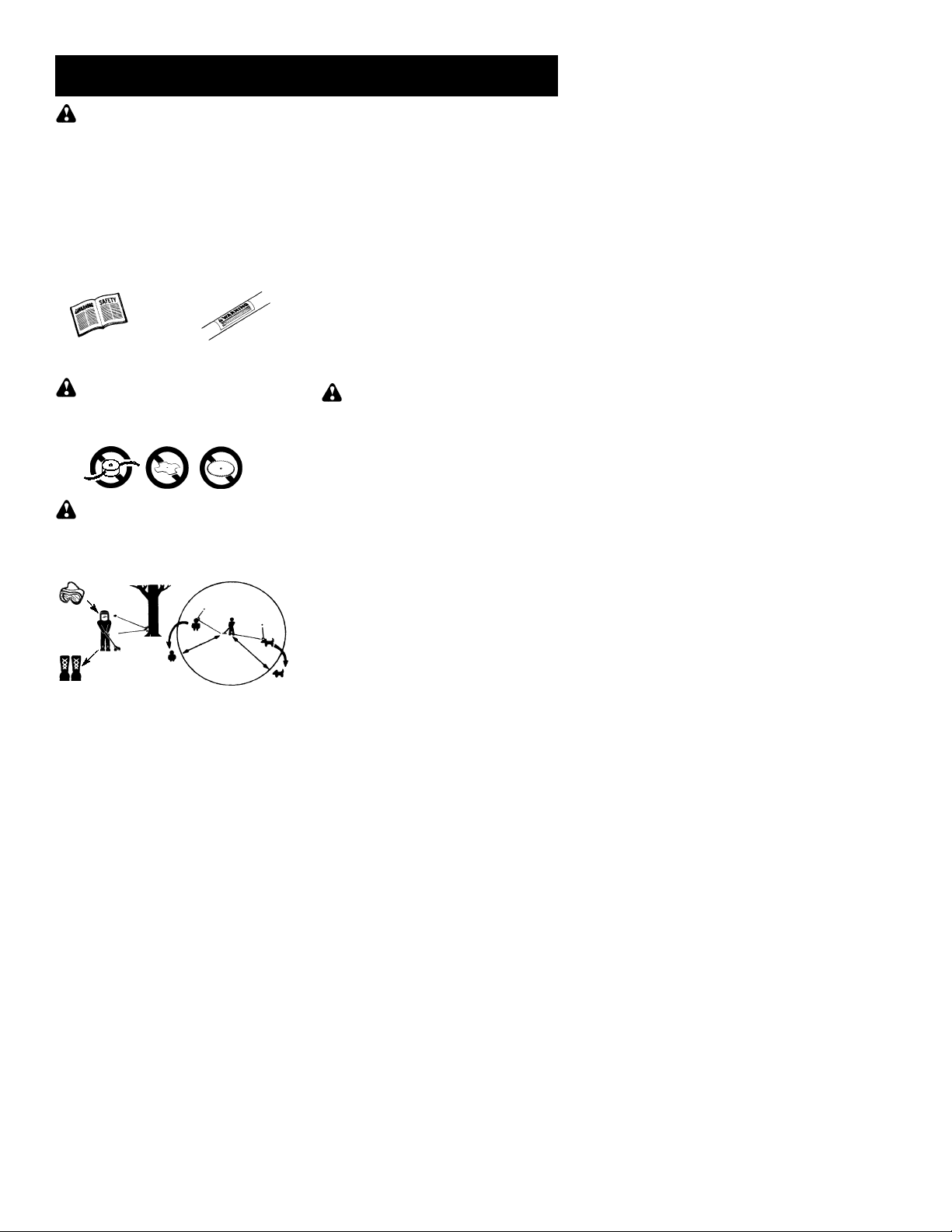
flailing devices. Unit is designed for line trimmeruseonly.Useof anyotheraccessories or
attachments will increase the risk of injury.
WARNING:
jects violently. Youandothers can beblinded/
injured. Wear safety glasses and leg protection. Keep body parts clear of rotating line.
Safety Glasses or similar eye protection
Boots
Keep children, bystanders, and animals 50
feet (15meters)away. Ifapproached stop unit
immediately.
If situations occur which are not covered in
this manual, use care and good judgement. If
youneedassistance, contact yourauthorized
service dealer or call 1-800-554-6723.
OPERATOR SAFETY
Dress properly. Always wear safety glasses
S
or similar eye protection when operating, or
performing maintenance, on your unit (safety
glasses areavailable). Eye protection should
be marked Z87.
Always wearfaceordust mask if operation is
S
dusty.
Whenusinggardening ap-
Operator
SAFETY INFORMATION
ON THE UNIT
Never use blades, wire or
Trimmer line throws ob-
HAZARD ZONE
50 ft.
(15 m)
Alwayswearheavy,longpants,longsleeves,
S
boots, andgloves. Wearingsafetylegguards
is recommended.
Always wearfootprotection. Do not go bare-
S
foot or wear sandals. Stay clear of spinning
line.
Securehairabove shoulderlength. Secure or
S
removeloose clothing orclothin gwith loosely
hanging ties, straps, tassels, etc. They can
be caught in moving parts.
Being fully covered also helps protect you
S
from debris and pieces of toxic plants thrown
by spinning line.
Stay Alert. Do not operate this unit when you
S
are tired,ill,upsetorunder the influence ofalcohol, drugs, or medication. Watch what you
are doing; use common sense.
Wear hearing protection.
S
Never start or run inside a closed room or
S
building. Breathing exhaust fumes can kill.
Keep handles free of oil and fuel.
S
UNIT / MAINTENANCE SAFETY
DANGER:
the clutch shroud removed. The clutch will fly
apart and cause serious injury.
Turnengine offanddisconnect sparkplugbe-
S
foreperformingmaintenance except carburetor adjustments.
Inspect unit before use. Look for and replace
S
damaged or loose parts before each use.
Make sureall handles, guards,andfasteners
are in place and securely fastened. Look for
andrepairfuel leaksbeforeuse.Keep ingood
working condition.
Replace trimmer head that is chipped,
S
cracked, broken, or damaged in any other
way before using the unit.
Maintain unitaccordingto recommended pro-
S
cedures. Keep cutting line at proper length.
Use only 0.115” diameter Weed Eater
S
brand cut length line (see REPLACING
THE LINE). Never use wire, rope, string,
etc.
Make sure unit is assembled correctly as
S
shown in this manual.
Make carburetor adjustments with lower
S
end supported to prevent line fromcontacting any object.
Keep others away when making carburetor
S
adjustments.
Use only recommended Weed EaterRac-
S
cessories and replacement parts.
Have all maintenance and service not ex-
S
plained inthismanual performedby anauthorized service dealer .
Never start the engine with
FUEL SAFETY
Mix and pour fuel outdoors.
S
Keep away from sparks or flames.
S
Use a container approved for fuel.
S
Do not smoke orallow smoking near fuel or
S
the unit.
Avoidspilling fueloroil. Wipe upall fuel spills.
S
2
R
Page 3
Move at least 10 feet (3 meters) away from
S
fueling site before starting engine.
Stop engine and allow to cool before remov-
S
ing fuel cap.
Always store gasoline in a container ap-
S
proved for flammable liquids.
CUTTING SAFETY
WARNING:
each use. Remove objects (rocks, broken
glass, nails, wire, etc.) which can be thrown
by or become entangled in line. Hard objects
can damage trimmer head and be thrown
causing serious injury.
Use unit properly. Use only for trimming,
S
mowing, and sweeping. Do not use for edging, pruning, or hedgetrimming. Do not force
unit. It will do the job better, and with lessrisk
of injury , at the rate forwhichit wasdesigned.
Keep firm footing and balance. Do not over-
S
reach.
Keep all parts of your body away from spin-
S
ning line andmuffler.Keepengine andcutting
head below waist level. A hot muffler can
cause serious burns.
Cut only from your right to your left. Cutting
S
with the line on right side of the shield will
throw debris away from the operator.
Useonlyindaylight or ingoodartificial light.
S
Use only for jobs explained in this manual.
S
Inspect the area before
TRANSPORTING AND STORAGE
Stop the unit when not in use.
S
Carry or transport the unit with engine
S
stopped.
Allow the engine to cool; secure unit before
S
storing or transporting in vehicle.
Empty the fuel tank before storing or trans-
S
porting the unit. Use up fuel left in the carburetor by starting the engine and letting it
run until it stops.
Store unit and fuel inanareawhere fuel va-
S
pors cannot reach sparks or open flames
from water heaters, electric motors or
switches, furnaces, etc.
Store the unit out of the reach of children
S
SPECIAL NOTICE:
equipped with a temperature limiting muffler
and spark arresting screen which meets the
requirements of California Codes 4442 and
4443. All U.S. forest land and the states of
California, Idaho, Maine, Minnesota, New
Jersey, Oregon, and Washington require by
law that many internal combustion engines to
be equipped with a spark arrestor screen. If
you operate in a locale where such regulations exist, you are legally responsible for
installing and maintaining the operating condition of these parts. Failure todosois aviolation of the law. If a spark arrestor is required
in your area, contact your authorized service
dealer for the proper kit.
SAFETY NOTICE:
through prolonged use of gasoline powered
hand tools could cause blood vessel ornerve
damage in the fingers, hands, and joints of
people prone to circulation disorders or abnormal swellings. Prolonged use in cold
weather hasbeenlinked tobloodvesseldamage inotherwise healthy people. If symptoms
occur such as numbness, pain, loss of
strength, change in skin color or texture, or
loss of feeling in the fingers, hands, or joints,
discontinue the useofthis tool and seekmedical attention. An anti-vibration system does
not guarantee the avoidance of these problems. Users who operate power tools on a
continual and regular basis must monitor
closely their physical condition and the condition of this tool.
This unit is not
Exposure to vibrations
ASSEMBLY
WARNING:
repeat all steps to ensure your unit is properly
assembled and all fasteners are secure.
Examine parts for damage. Do not use damaged parts.
NOTE:
missing or damaged, call 1-800-554-6723.
It is normal for the fuel filter to rattle in the
empty fuel tank.
Finding fuel or oil residue on muffler is normal
due to carburetor adjustments and testing
done by the manufacturer.
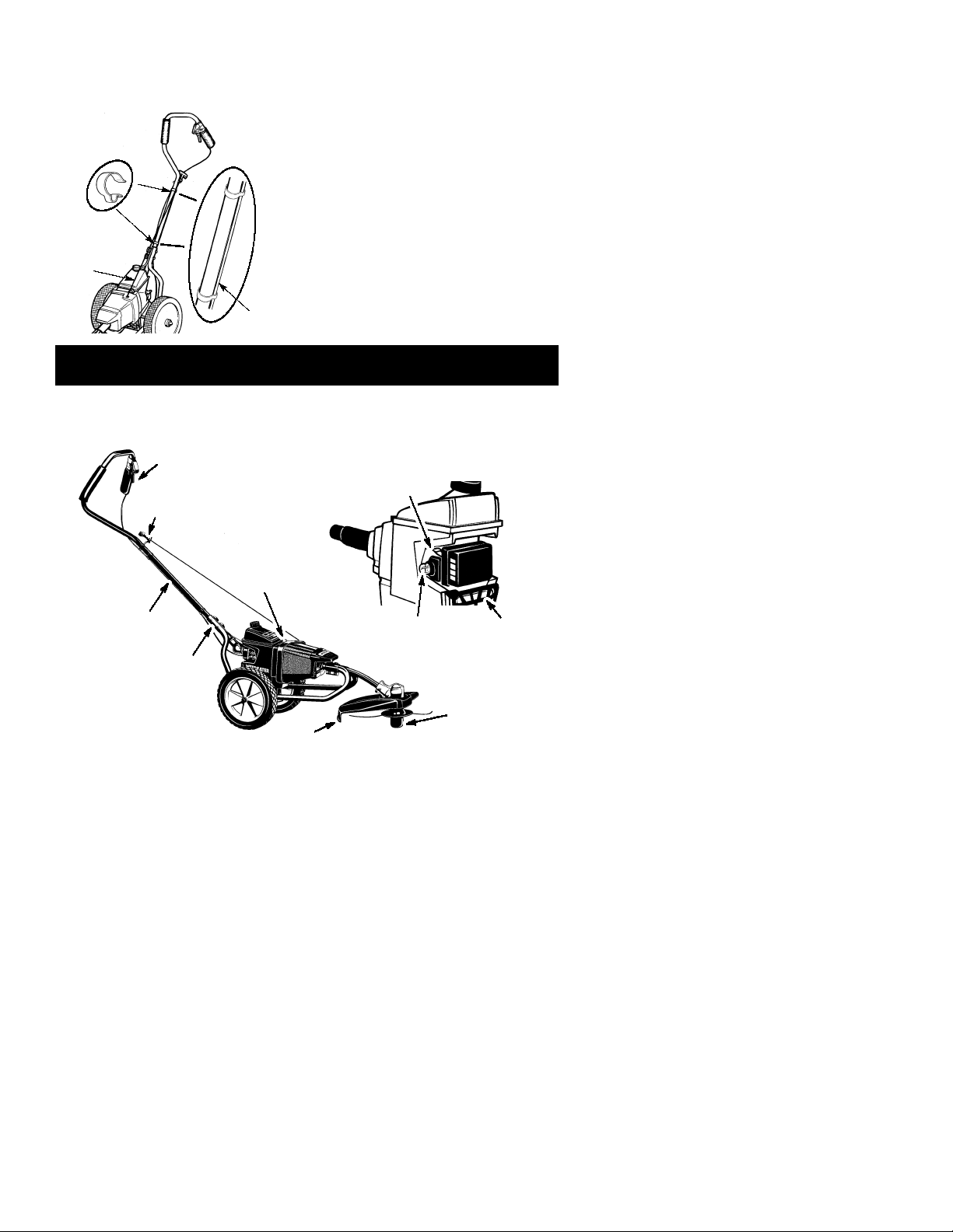
ATT ACHTHE HANDLE
1. Remove upper wing nut and curved head
2. Loosen lower wing nut on lower handle.
3. Insert upper handle over lower handle.
NOTE:
position asshownin the following illustrations
(throttle handle grip on left side).
If you need assistance or find parts
tube bolt from upper handle.
Ensure upper handle grips are in
If received assembled,
4. Align holes and insert curved head tube
bolt through upper and lower handles.
5. Re--install andsecurelytighten upper wing
nut onto bolt.
6. Retighten lower wing nut securely.
Upper handle
Lower handle
Upper wing nut
Lower wing nut
3
Tube bolt
Page 4
NOTE:
be sure the starter rope is not caught under
the cable clamps.
hang freely to operate properly.
When performing the following step,
The starter rope must
Cable
clamps
Starter rope
Throttle
cable
7. Align onecable clamp above the tubebolts
and the other below the starter rope handle. Install the cable clamps one at a time
around the tube and throttle cable.
NOTE:
clamps and lies flat against the upper handle
tube after installation (see illustration above).
Ensure throttle cable is in groove of
OPERATION
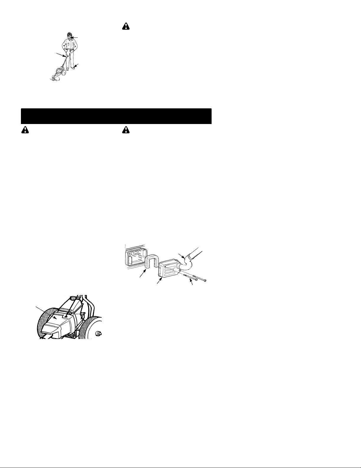
KNOW YOUR TRIMMER
READ THIS INSTRUCTION MANUAL ANDSAFETY RULES BEFORE OPERATING YOUR UNIT .
Comparetheillustrations with your unit to familiar iz eyou r s e lfwith the location of the variouscon tr o ls
and adjustments. Save this manual for future reference.
Throttle Trigger
Starter Rope
Handle
ON/OFF
Switch
Upper Handle
Lower Handle
Shield
ON/OFF SWITCH
The ON/OFF switch is used to stop engine. To
stop the engine, move the switch to the OFF
position.
PRIMER BULB
The PRIMER BULBremovesairfrom the carburetor and fuel lines and fills them with fuel.
This allows you to start the engine with fewer
pulls on the starter rope. Activate the primer
bulb by pressing it and allowing it to return to
its original form.
Choke Lever
Shield
Primer Bulb
Muffler
Trimmer Head
CHOKE
The CHOKE helps to supply fuel to the engine
to aid in cold starting. Activate the choke by
moving the choke lever to the FULL CHOKE
position. Afterthe engineattemptsto start, move
the choke lever to the HALF CHOKE position.
Once engine hasstarted,movethe choke lever
to the OFF CHOKE position.
4
Page 5

BEFORE STARTING ENGINE
WARNING:
information in the safety rules before you begin. If you do not understand the safety rules,
do not attempt to fuel your unit. Call
1-800-554-6723.
Be sure to read the fuel
FUELING ENGINE
WARNING:
when refueling.
This engine is certified to operate on unleaded gasoline. Before operation, gasoline
must be mixed with a good quality synthetic
2-cycle air-cooled engine oil designed to be
mixed at a ratio of 40:1. Poulan/Weed Eater
brand synthetic oil is recommended. Mix gasoline and oil at a ratio of 40:1. A 40:1 ratio is
obtained by mixing 3.2 ounces (95 ml) of oil
with 1 gallon (4 liters) of unleaded gasoline.
DO NOT USE automotive oil or boat oil.
These oils will cause engine damage. When
mixing fuel, follow instructions printed oncontainer. Once oil is added to gasoline, shake
container momentarily to assure that the fuel
is thoroughly mixed. Always read and follow
the safety rules relating to fuel before fueling
your unit.
Remove fuel cap slowly
IMPORTANT
Experience indicates that alcohol blended
fuels (called gasohol or using ethanol or
methanol) can attract moisture which leads to
separation and formation of acids during storage. Acidic gas can damage the fuel system
of anengine while in storage. Toavoidengine
problems, empty the fuel system before storage for 30 days or longer. Drain the gas tank,
start the engine and let itrununtil thefuellines
and carburetor are empty. Use fresh fuel next
season.Never use engine or carburetor
cleaner products inthefueltankorpermanent
damage may occur. See the STORAGE section for additional information.
HOW TO STOP YOUR UNIT
To stop the engine, move the ON/OFF
S
switch to the OFF position until the unit has
fully stopped.
If engine does not stop, move choke to the
S
FULL CHOKE position.
ON/OFF
Switch
Choke Lever
Primer Bulb
Muffler
HOW TO START YOUR UNIT
WARNING:
turn while starting the engine. Avoid any con-
The trimmer head will
tact with the muffler. A hot muffler can cause
serious burns.
STARTING A COLD ENGINE (or a
warm engine after running out of
fuel)
1. Move ON/OFF switch to the ON position.
2. Slowly press the primer bulb 6 times.
3. Move choke lever to the FULL CHOKE
position.
4. Squeeze the throttle trigger fully and hold
through
5. Pull starter rope handle sharply until engine
6. As soon as engine sounds asif it is trying to
7. Pull starter rope sharply until engine runs,
8. Once the engine starts, allow it to run 10
all remaining steps.
soundsasif it is tryingtostart, but do not pull
rope more than 6 times.
start, move choke lever to HALF CHOKE
position.
but no more than 6 pulls.
gine doesn’t start after 6 pulls (attheHALF
CHOKEposition), move thechokeleverto
the FULL CHOKE position and press the
primer bulb 6 times. Squeeze and hold the
throttle trigger and pull the starter rope 2
more times. Move the choke lever to the
HALF CHOKE position and pull the starter
rope until the engine runs, but no more
than 6pulls. If the engine still doesn’t start,
it is probably flooded. Proceed to STARTING A FLOODED ENGINE.
seconds, then move the choke lever to the
OFF CHOKEposition. Allow theunit torun
for 30 more seconds at OFF CHOKE before releasing the throttle trigger.
NOTE:
ver in the OFF CHOKEposition, movethe
choke lever to the HALF CHOKE position
and pull the rope until engine runs, but no
more than 6 pulls.
If engine dies with the choke le-
NOTE
: If the en-
STARTING A WARM ENGINE
1. Move ON/OFF switch to the ON position.
2. Move the choke lever to the HALF CHOKE
position.
3. Squeeze and hold the throttle trigger. Keep
throttle triggerfullysqueezeduntiltheengine
runs smoothly.
4. Pull starter rope sharply until engine runs,
but no more than 5 pulls.
5. Allow engine to run 15 seconds, then move
the choke lever to OFF CHOKE.
If engine has not started, pull starter
NOTE:
rope 5more pulls. If engine still does not run,it
is probably flooded.
STARTING A FLOODED ENGINE
Flooded engines can be started by placing
the choke lever in the OFF CHOKE position;
then, pull the rope to clear the engine of excessfuel.Thiscould require pulling the starter
handle many times depending on how badly
the unit is flooded.
If the unit still doesn’t start, refer to
TROUBLESHOOTING TABLE or call
1-800-554-6723.
5
Page 6
OPERATING INSTRUCTIONS
OPERATING POSITION
ALWAYS USE:
Heavy Long
Pants
Cut from your right to your left.
NOTE:
during operation of unit as shown above to
avoid covering air intake holes located on underside of upper handle.
Keep left and right hands on grips
Eye
Protection
Heavy
Shoes
MAINTENANCE
WARNING:
tion. Never lean over the trimmer head.
Rocks ordebris can ricochet orbethrown into
eyes and face and cause blindness or other
serious injury.
Do not run the engine at a higher speed than
necessary. The cutting line will cut efficiently
when the engine is run at less than full throttle.
At lower speeds, thereis less engine noise and
vibration.
Always release the throttle trigger and allow the
engine to return to idle speed when not cutting.
To stop engine:
Release the throttle trigger.
S
Move the ON/OFF switch to the OFF posi-
S
tion.
Always wear eye protec-
WARNING:
plug before performing maintenance except
for carburetor adjustments.
Disconnect the spark
CHECK FOR LOOSE
FASTENERS AND PARTS
Spark Plug Boot
S
Air Filter
S
Housing Screws
S
Debris Shield
S
CHECK FOR DAMAGED OR
WORN PARTS
Contact an authorized service dealer for replacement of damaged or worn parts.
ON/OFF Switch -- Ensure ON/OFF switch
S
functions properly by moving the switch to
the OFF position. Make sure engine stops;
then restart engine and continue.
Fuel Tank -- Discontinue use of unit if fuel
S
tank shows signs of damage or leaks.
Debris Shield -- Discontinue use of unit if
S
debris shield is damaged.
INSPECT AND CLEAN UNIT AND
LABELS
After each use, inspect complete unit for
S
loose or damaged parts. Clean the unit and
labels using a damp cloth with a mild detergent.
Wipe off unit with a clean dry cloth.
S
CLEAN THE AIR INTAKE SCREEN
The air intake screen allows airto circulate to
keep the engine functioning properly and prevents debris from entering the engine.
Air intake screen
WARNING:
tempting to clean the intake screen. DONOT
USE GARDEN HOSE OR PRESSURE
WASHER TO CLEAN THIS UNIT!
Clean the intake screen periodically with a
S
nylon brush.
top your unit before at-
S
CLEAN THE AIR FILTER
A dirty air filter decreases engine performance and increases fuel consumption and
harmful emissions. Always clean with engine
stopped. Cleanfilterafterevery5 hours ofoperation.
1. Clean the air filter cover and the area
around thecovertoprevent dirt fromfalling
into the carburetor chamber when thecover is removed.
2. Remove parts as illustrated. It is not necessary to remove the air filter hose from
the air filter cover.
NOTE:
tached from the cover or lower handle during
cleaning, reattach before attempting torestart
the engine or operate the unit.
NOTE:
er flammable solvent to avoid creating a fire
hazard or producing harmful evaporative
emissions.
3. Wash the filter in soap and water.
4. Allow filter to dry.
5. Add 10 -- 15 drops of oil to the filter;
NOTE:
6. Replace parts.
6
If the air filter hose becomes unat-
Air Filter
Hose
Air
Filter
Air Filter Cover
Do not clean filter in gasoline or oth-
squeeze the filter to distribute oil.
FILTER MUST BE OILED!
Screws
Page 7
REPLACE SPARK PLUG
Replace the spark plug each year to ensure
the engine starts easier and runs better. Set
spark plug gap at0.025 inch. Ignition timing is
fixed and nonadjustable.
SERVICE AND ADJUSTMENTS
REPLACING THE LINE
For unit to operate properly, the cutting line
should be replaced when line becomes wornto
less than3inchesinlengthfrom the edge of the
lineexittunnels oneachside ofthecuttinghead.
WARNING:
with engine switch in the OFF position.
1. Remove and discard worn line before
installing new line.
2. Use only .115” diameter Weed Eater
brand cut length line.
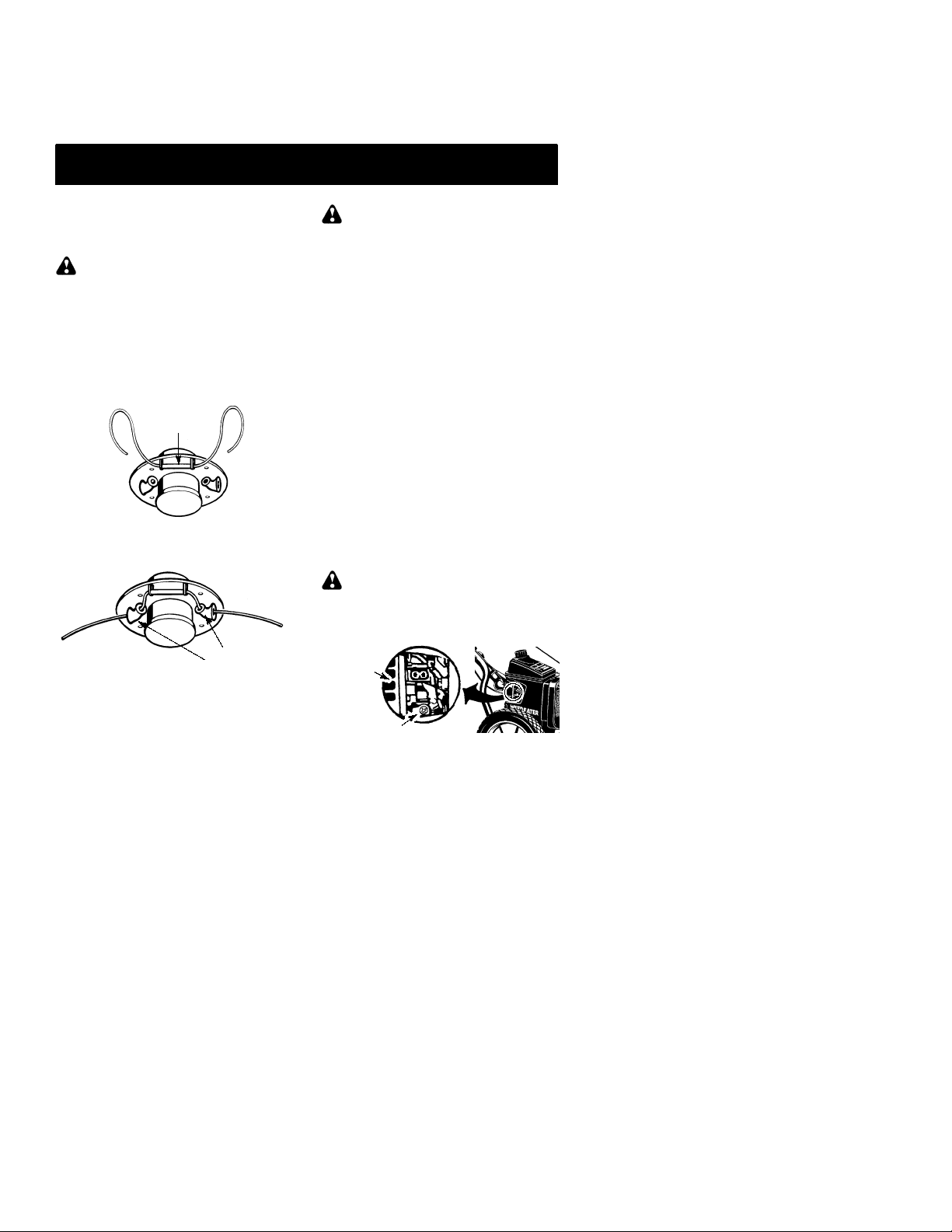
3. Insert one end of the line through the positioning tunnel.
4. Continue to feed line through tunnel until
line is centered (leaving equal amounts on
each side). See illustration below.
5. Insert endsof line oneatatime through the
line exit tunnels.
6. Pull the line and make sure the line is extended fully through the tunnels.
Only replace cutting line
R
Positioning
tunnel
1. Twist, then pull off spark plug boot.
2. Remove spark plug from cylinder and discard.
3. Replace with Champion RCJ-6Ysparkplug
and tighten securely with a 3/4 inch socket
wrench.
4. Reinstall the spark plug boot.
CARBURETOR ADJUSTMENTS
WARNING:
making idle speed adjustments. The trimmer
head will be spinning during most of this procedure. Wear your protective equipment and
observe all safety precautions. After making
adjustments, the trimmer head must not
move/spin at idle speed.
The carburetor has been carefully set at the
factory. Adjustments may benecessary ifyou
notice any of the following conditions:
Engine will not idle when the throttle is re-
S
leased.
The trimmer head moves/spins at idle.
S
Make adjustments with the unit supported so
the cutting attachment is off the ground and
will not make contact with any object. Hold
the unit byhandwhilerunningandmakingadjustments. Keep all parts of your body away
from the cutting attachment and muffler.
Keep others away when
Idle Speed Adjustment
Allow engine to idle. Adjust speed until engine
runs without trimmer head moving orspinning
(idle too fast) or stalling (idle speed too slow).
Turn idle speed screw clockwise to in-
S
crease engine speedifengine stalls ordies.
Turn idle speed screw counterclockwise to
S
decrease engine speed if trimmer head
moves or spins at idle.
WARNING:
after each adjustment. The trimmer head
must not move or spin at idle speed to avoid
serious injury to the operator or others.
Recheck the idle speed
Line exit
7. Correctly installed line will be the same
length on both ends.
tunnels
Air Filter
Cover
Idle Speed Screw
If yourequire further assistance or areunsure
about performing this procedure, contact an
authorized service dealer or call
1--800--554--6723.
7
Page 8

STORAGE
WARNING:
steps after each use:
Allow engine to cool, and secure the unit
S
before storing or transporting.
Store unit and fuel in a well ventilated area
S
where fuel vapors cannot reach sparks or
open flames from water heaters, electric
motors or switches, furnaces, etc.
Store unit with all guards in place. Position
S
unit so that any sharp object cannot accidentally cause injury.
Store unit and fuel well out of the
S
children.
SEASONAL STORAGE
Prepare unit for storage at end of season or if
it will not be used for 30 days or more.
If your unit is to be stored for a period of time:
Clean the entire unit before lengthy storage.
S
Store in a clean dry area.
S
Lightly oil external metal surfaces.
S
FUEL SYSTEM
Under FUELING ENGINE in the OPERATION section of this manual, seemessagelabeledIMPORTANT regarding the use of gasohol in your engine.
Perform the following
reach of
Fuel stabilizer is an acceptable alternative in
minimizing the formation of fuel gum deposits
during storage. Add stabilizer to the gasoline
in the fuel tank or fuel storage container. Follow the mix instructions found on stabilizer
container. Run engine at least 5 minutes after
adding stabilizer.
ENGINE
Remove spark plug and pour 1 teaspoon of
S
40:1, 2-cycleengine oil (air cooled) through
the spark plug opening. Slowly pull the
starter rope 8 to 10 times to distribute oil.
Replace spark plug with new one of recom-
S
mended type and heat range.
Clean air filter.
S
Check entire unit for loose screws, nuts,
S
and bolts. Replace any damaged, broken,
or worn parts.
At the beginning of the next season, use
S
only fresh fuel having the propergasoline to
oil ratio.
OTHER
Do not store gasoline from one season to
S
another.
Replace your gasoline can if itstarts torust.
S
8
Page 9

TROUBLESHOOTING TABLE
WARNING:
recommended remedies below except remedies that require operation of the unit.
Always stop unitanddisconnect spark plugbeforeperforming all ofthe
TROUBLE CAUSE REMEDY
Engine will not
start.
Engine will
not idle
properly.
Engine will not
accelerate,
lacks power,
or dies under
a load.
Engine
smokes
excessively.
Engine runs
hot.
1. Engine flooded.
2. Fuel tank empty.
3. Spark plug not firing.
4. Fuel not reaching
carburetor.
5. Carburetor requires
adjustment.
1. Carburetor requires
adjustment.
2. Crankshaft seals worn.
3. Compression low.
1. Air filter dirty.
2. Spark plug fouled.
3. Carburetor requires
adjustment.
4. Carbon build-up on
muffler outlet screen.
5. Compression low.
1. Choke partially on.
2. Fuel mixture incorrect.
3. Air filter dirty.
4. Carburetor requires
adjustment.
1. Fuel mixture incorrect.
2. Spark plug incorrect.
3. Carburetor requires
adjustment.
4. Carbon build-up on
muffler outlet screen.
1. See “Starting a Flooded Engine” in
Operation Section.
2. Fill tank with correct fuel mixture.
3. Install new spark plug.
4. Check for dirty fuel filter; replace.
Check for kinked or split fuel line;
repair or replace.
5. Contact an authorized service dealer.
1. See “Carburetor Adjustment” in
Service and Adjustments Section.
2. Contact an authorized service dealer.
3. Contact an authorized service dealer.
1. Clean or replace air filter.
2. Clean or replace plug
and regap.
3. Contact an authorized service dealer.
4. Contact an authorized service dealer.
5. Contact an authorized service dealer.
1. Adjust choke.
2. Empty fuel tank and refill with
correct fuel mixture.
3. Clean or replace air filter.
4. Contact an authorized service dealer.
1. See “Fueling Engine” in Operation
section.
2. Replace with correct spark plug.
3. Contact an authorized service dealer.
4. Contact an authorized service dealer.
9
Page 10

LIMITED WARRANTY
ELECTROLUX HOME PRODUCTS, INC.,
warrants to the original purchaser that each
Weed Eater
new
tachment is free from defects in material and
workmanship and agrees to repair or replace
under this warranty any defective gasoline
product or attachment as follows from the
original date of purchase.
2YEARS--
household purposes.
60 DA YS --
commercial, professional, or income producing purposes.
30 DAYS --
purposes.
This warranty isnottransferable and does not
cover damage or liability caused by improper
handling, improper maintenance, or the use
of accessories and/or attachments not specifically recommended by
HOME PRODUCTS, INC.,
tionally, this warranty does not cover tuneups, spark plugs, filters, starter ropes, starter
springs, cutting line, or rotating head parts
that will wear and require replacement with
reasonable use during the warranty period.
This warranty does not cover predelivery set-
brand gasoline tool or at-
Parts and Labor, when used for
Parts and Labor, when used for
Parts and Labor, if used for rental
ELECTROLUX
for this tool. Addi-
U.S. EPA / ENVIRONMENT CANADA
EMISSION CONTROL WARRANTY STATEMENT
YOUR WARRANTY RIGHTS AND OBLIGATIONS:
The U. S. Environmental Protection
Agency, Environment Canada and ELECTROLUX HOME PRODUCTS, INC., are
pleased toexplainthe emissions controlsystem
warranty on your year 2002--2004 small off-road engine. ELECTROLUX HOME PRODUCTS, INC., must warrantthe emission control
systemonyoursmalloff--roadenginefor theperiods of time listed below provided there has
been no abuse, neglect, or improper maintenanceofyoursmall off--road engine. Youremission control system includes parts such as the
carburetor and the ignition system. Where a
warrantable condition exists, ELECTROLUX
HOMEPRODUCTS, INC., will repairyoursmall
off--road engine at no cost to you. Expenses
covered under warranty include diagnosis,
parts and labor.
RANTY COVERAGE:
part on your engine (as listed under Emissions
ControlWar r antyParts List)isdefectiveor adefect in the materials or workmanship of the engine causes the failure of such an emission related part, the part will be repaired or replaced
by ELECTROLUX HOME PRODUCTS, INC.
OWNER’S WARRANTY RESPONSIBILITIES:
As the small off--road engine owner, you
are responsible for the performance of the required maintenance listed in your instruction
manual. ELECTROLUX HOME PRODUCTS,
INC., recommends that you retain all receipts
covering maintenance on your small off--road
MANUFACTURER’S WAR-
If any emissions related
upornormal adjustments explained in the operator’s manual.
THIS WARRANTY GIVES YOU SPECIFIC
LEGAL RIGHTS, AND YOU MAY HAVE
OTHER RIGHTS WHICH VARY FROM
STATE TO STATE.
NO CLAIMS FOR CONSEQUENTIAL OR
OTHER DAMAGES WILL BE ALLOWED,
AND THERE ARE NO OTHER EXPRESS
WARRANTIES EXCEPT THOSE EXPRESSLY STIPULATED HEREIN.
SOME STATES DO NOT ALLOW LIMITATIONS ON HOW LONGANIMPLIED WARRANTY LASTS OR THE EXCLUSION OR
LIMITATIONS OF INCIDENTAL OR CONSEQUENTIAL DAMAGES, SO THE ABOVE
LIMITATIONS OR EXCLUSION MAY NOT
APPLY TO YOU.
The policy of
UCTS, INC.,
products. Therefore,
PRODUCTS, INC.,
change, modify, or discontinue models, designs, specifications, and accessories of all
products at any time without notice orobligation to any purchaser.
engine, but ELECTROLUX HOME PRODUCTS, INC., cannot deny warranty solely for
the lack of receipts or for your failure to ensure
the performance of all scheduled maintenance.
As the small off--road engine owner,youshould
be aware that ELECTROLUX HOME PRODUCTS, INC., may deny you warranty coverage
if your small off--road engine or a part of it has
failed due to abuse, neglect, improper maintenance, unapproved modifications, or the use of
parts not made or approved by the original
equipment manufacturer. You are responsible
for presenting your small off--road engine to an
ELECTROLUX HOME PRODUCTS, INC., authorized repaircenterassoon as a problem exists. Warranty repairs should be completed in a
reasonable amount of time, not to exceed 30
days. If you have anyquestions regardingyour
warranty rights and responsibilities, you should
contact your nearest authorized service center
or call ELECTROLUX HOME PRODUCTS,
INC., at 1--800--554--6723.
COMMENCEMENT DATE:
od begins on the date the small off--road engine
is purchased.
warranty shall be for a period of two years from
the initial date of purchase.
ERED: REPAIR OR REPLAC EM ENT OF
PARTS.
rantedpartwill be performedat no charge to the
owner at an approved ELECTROLUX HOME
PRODUCTS, INC., servicing center. If you
have any questions regarding your warranty
10
ELECTROLUX HOME PROD-
is to continuously improve its
ELECTROLUX HOME
reserves the right to
WARRANTY
The warranty peri-
LENGTH OF COVERAGE:
WHA T IS COV-
Repair or replacement of any war-
This
Page 11
rights and responsibilities, you should contact
your nearest authorized service center or call
ELECTROLUX HOME PRODUCTS, INC., at
1--800--554--6723.
warranted part which is not scheduled for replacement asrequired maintenance, orwhichis
scheduled only for regular inspection to the effect of “repair or replace as necessary” shall be
warrantedfor 2years. Anywarr antedpart which
is scheduled for replacement as required maintenance shallbewarrantedforthe periodoftime
up to the first scheduled replacement point for
that part.
charged for diagnostic labor which leads to the
determination that a warranted part is defective
if the diagnostic work is performed at an approved ELECTROLUX HOME PRODUCTS,
INC., servicing center.
DAMAGES:
UCTS,INC.,may be liablefordamages toother
engine components caused by the failure of a
warranted part still under warranty.
NOTC OVERED:
neglect, or improper maintenance are not covered.
useofadd--on ormodifiedpartscan be grounds
DIAGNOSIS:
ADD--ON OR MODIFIED PARTS:
WARRANTY PERIOD:
The owner shall not be
ELECTROL UX HOME PROD-
CONSEQUENTIAL
All failures caused by abuse,
WHA T IS
LUX HOME PRODUCTS, INC., is not liable to
cover failures of warranted parts caused by the
useofadd--onormodifiedparts.
ACLAIM:
Any
your warranty rights and responsibilities, you
should contact your nearest authorized service
center or call ELECTROLUX HOME PRODUCTS, INC., at 1--800--554--6723.
GET WARRANTY SERVICE:
vices or repairs shall be provided at all ELECTROLUX HOME PRODUCTS, INC., service
centers. Call 1--800--554--6723.
NANCE, REPLACEMENT AND REPAIR OF
EMISSION RELATED PARTS:
TROLUX HOME PRODUCTS, INC., approved
replacement part used in the performance of
any warranty maintenance or repair on emission related parts will be provided without
chargetothe owner ifthe partisunder warranty.
EMISSION CONTROL WARRANTY PARTS
LIST:
(covered up to maintenance schedule), Ignition
Module.
owner is responsible for the performance of all
The
required maintenance as defined in the instruction manual.
If you have any questions regarding
Carburetor, Ignition System: Spark Plug
MAINTENANCE STATEMENT:
HOW TOFILE
WHERE TO
Warranty ser-
Any ELEC-
for disallowing a warranty claim. ELECTRO-
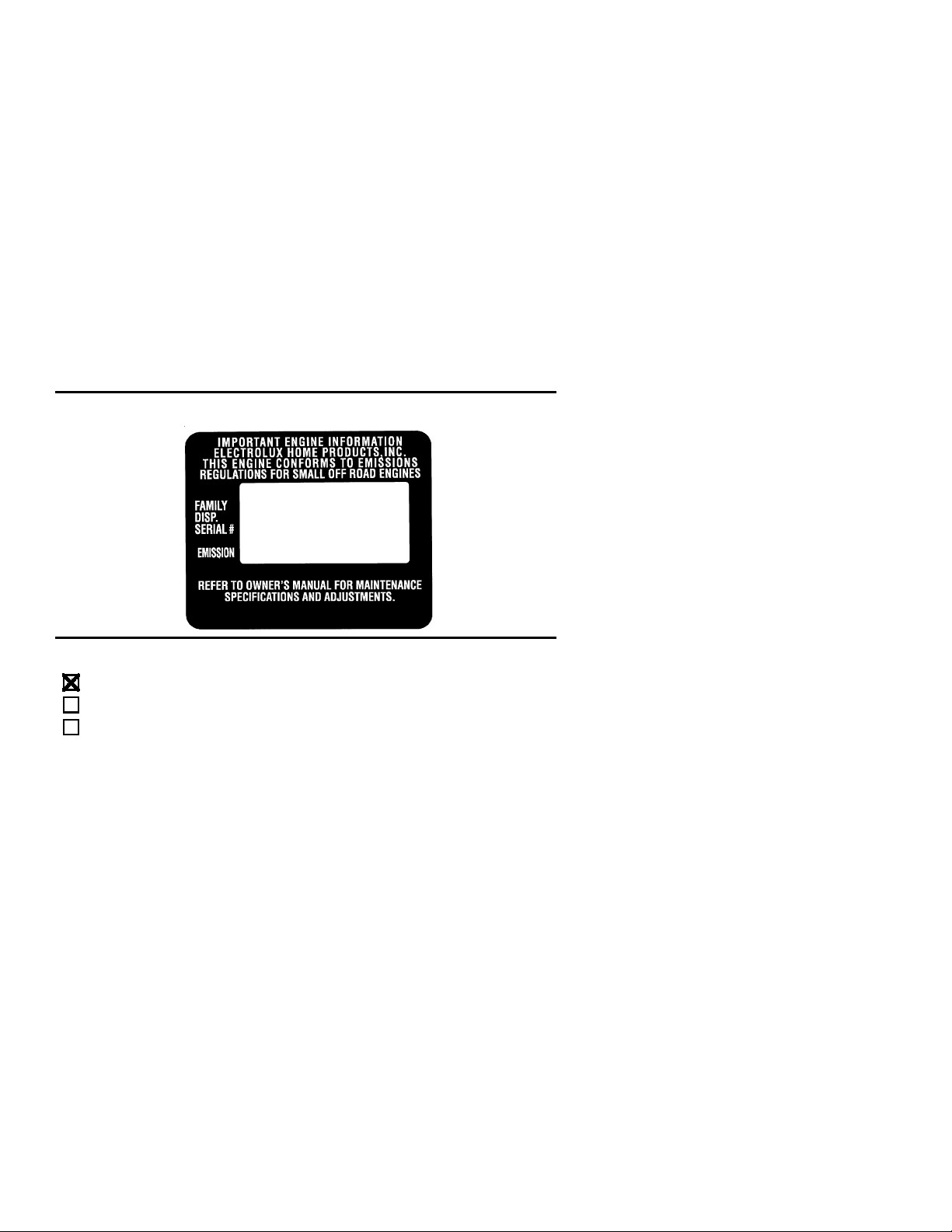
The information on the product label indicates which standard your engine is certified.
Example: (Year) EPA Phase 1 or Phase 2 and/or CALIFORNIA.
MAINTE-
The
This engine is certified to be emissions compliant for the following use:
Moderate (50 hours)
Intermediate (125 hours)
Extended (300 hours)
11
 Loading...