

Page 1

Instruction handbook
Washer-extractors
WS4250H – WS4350H – WS4500H – WS4650H
WSB4250H – WSB4350H – WSB4500H – WSB4650H
01201138/GB
14.10
Page 2

.
Page 3

INSTRUCTION
HANDBOOK
Table of contents
01201138
Notice
0907
Date
0
0
Page
Pages/Chapters
General instructions
General ................................................... 1/1
Precautions for use ................................. 1/2
Environmental information ...................... 1/3
Preliminary instructions ........................... 1/4
Locking and tagging procedure .............. 1/5
Handling/Weight
Handling .................................................. 1/6
Packing - Weight ..................................... 1/7
Technical characteristics
Technical characteristics ......................... 1/8
Sound level ............................................ 17/8
Label of energetic performances ........... 17/8
Installation/Putting into service
Installation ............................................... 1/9
Working place lighting ............................. 2/9
Supplies .................................................. 2/9
Mechanical installation ............................ 3/9
Fitting of the safety fl anges ..................... 4/9
Fitting of the fi lling angles ....................... 5/9
Assembling of the partition for
barrier machine ....................................... 6/9
Water connections .................................. 7/9
Steam connection ................................... 8/9
Indirect steam heating .............................. 9/9
Drain connection .................................... 10/9
Air vent connection ................................ 11/9
Installation of the gas exchanger ........... 11/9
Connection of the evacuation pipe of
the gas exchanger ................................. 13/9
Gas connection ...................................... 15/9
Liquid detergents connection ................. 22/9
Electrical connection .............................. 25/9
Remove of the transport locks fi tted ...... 30/9
Operating inspection
Manual operation ................................... 1/10
Automatic operation ............................... 2/10
Machine operation
Auxiliary control .................................... 1/11
Automatic operation ............................... 3/11
Detergent dispenser .............................. 5/11
To run a wash program .......................... 6/11
The "move back" key ............................. 6/11
To start the wash program ..................... 7/11
To start a wash program from the
program library ...................................... 10/11
To change parameters in the current
program step ......................................... 13/11
Pages/Chapters
Rapid advance ...................................... 14/11
Show weight ......................................... 15/11
Pause .................................................... 17/11
Manual operation during a program ...... 18/11
Text ....................................................... 24/11
To change the wash program after
program operation has commenced ..... 25/11
To change temperature scale °C/ °F ..... 26/11
Auto restart ........................................... 27/11
Manual operation
To select a manual operation ................ 28/11
Motor/door ............................................ 29/11
Water/drain ........................................... 30/11
Heating ................................................. 31/11
Detergent signals and water fl ushing .... 32/11
At the end of the wash .......................... 33/11
Statistics
To select "statistics" .............................. 35/11
Resetting statistic registers ................... 37/11
Automatic weighing
Scale adjustments ................................ 42/11
ON/OFF and pause
On/off and pause by exterior signals .... 53/11
Memory card
General introduction ............................. 54/11
To select the "Memory card" function .... 55/11
To run a wash program straight from
a memory card ..................................... 58/11
To copy a program from a memory card
to the machine's program control unit ... 59/11
To copy a program from the program
control unit to a memory card ............... 61/11
To delete a program on a
memory card ......................................... 63/11
To delete all programs on a
memory card ......................................... 64/11
Weighing equipment .............................. 65/11
Safety
Safety ..................................................... 1/12
Maintenance
Operating incidents ................................ 1/13
Preventive maintenance ........................ 1/14
Electric diagrams
Electric diagrams ................................... 1/15
Appendices
Convertion measurement units .............. 1/16
Washing symbols ................................... 2/16
The manufacturer reserves the right to modify construction and equipment characteristics.
Page 4

01201138
Notice
0107 1
Date
Page
1
1. General
General instructions
The machines described in this handbook have a washing capacity of 229, 338, 467 or 668
litres according to their type.
They are washer-extractors designed to meet the most severe requirements.
They are designed to be installed in hotels, laundries, hospitals or collectivities.
The suspension device mounted with springs and shock absorbers limits to the maximum
ground vibrations.
A important G factor guarantees the highest extraction quality for your linen.
These machines also exist in barrier version allowing the respect of linen's hygiene rules.
INSTRUCTION
HANDBOOK
Identifi cation
plate
GAS EXCHANGER
Adjustment label
D0630A/434
Page 5

INSTRUCTION
HANDBOOK
1. General
01201138
Notice
0107 2
Date
Page
This washer extractor is controlled by a microprocessor-based program control unit placed on
the loading side. There are many advantages to this equipment, including :
• Timing, levels and temperatures are controlled with great precision and fl exibility.
• The large display screen means that detailed information on wash programs, machine status
and operations, wash times and temperatures can be accessed in plain language
• It is possible for the user to create new wash programs, and to adapt programs with great
precision, on the basis of experience and to suit various types of textile, degrees of soiling
etc.
• a very high level of machine safety through continuous monitoring and built-in safety interlocks.
• The program control unit has a reader for "smart cards". These are cards the size of a credit
card which contain a memory chip. Smart cards allow the user to :
- transfer wash programs between a PC and the washer extractor, or from one washer
extractor to another
1
- run programs straight from a card
• Great fl exibility during program operation :
- rapid advance both forwards and backwards in the program
- the user can change temperatures, program module lengths and extraction speeds direct-
ly, during program operation
- change to running a different wash program, at any time during program operation of the
washer extractor.
RUN A WASH PROGRAM
GO TO THE MENU
MAKE YOUR CHOICE WITH
OR PRESS SELECT
Display screen
Numeric keyboard
WEIGHT, KG 000,0
SELECT
Function keys.
The functions of these
keys change, depending
on which menu or part of a
menu you are using. Their
current functions at any time
are shown on the display
immediately above each key.
Card reader for
memory cards
During a wash : "Pause" key.
Before and after a wash, and during programming : "Move back key".
By pressing this key repeatedly you can move backwards through the menus you have navigated through. This will
always bring you back to the menu shown on the display in this illustration.
4221A
Page 6

0107 3
01201138
Notice
A very high working safety level of the machine is achieved thanks to a continuous monitoring
and built-in safety devices.
Even the compound textile fabrics can be washed at a high temperature with no crumpling risk
thanks to a special cooling process before the rinsing cycle.
In order to avoid an excessive mechanical fatigue during the hydro-extraction process, the
machine is equipped with an unbalance detector. If the latter detects the least unbalance of the
load, the hydro-extraction cycle is interrupted and the machine fi lls with water to make a new
distribution of the linen possible.
The machine then resumes the distribution speed and another hydro-extraction cycle begins.
The machine can also be controlled sequence by sequence and is equipped with a keyboard
for the manual control of certain functions.
0107 3
Date
Page
1
1
1. General
INSTRUCTION
HANDBOOK
Note about the A.C. power
• According to the EN 60204-1:1997 standard, the machine is provided for AC supplies
corresponding to the extracted caracteristics below :
4.3.2 AC supplies
Voltage:
Steady state voltage : 0,9…1,1 of nominal voltage.
Frequency:
0,99…1,01 of nominal frequency continuously.
0,98…1,02 short time.
Harmonics:
Harmonic distorsion not to exceed 10 % of the total r.m.s. voltage between live conductors for
the sum of the second through to the fi fth harmonic. An additional 2 % of the total r.m.s. voltage
between live conductors for the sum of the sixth through to the 30th harmonic is permissible.
Voltage unbalance:
Neither the voltage of the negative sequence component nor the voltage of the zero sequence
component in three-phase supplies shall exceed 2 % of the positive sequence component.
Voltage interruption:
Supply interrupted or at zero voltage for not more than 3 ms at any random time in the supply
cycle. There shall be more than 1s between successive interruptions.
Voltage dips:
Voltage dips shall not exceed 20 % of the peak voltage of the supply for more than one cycle.
There shall be more than 1 s between successive dips.
Page 7

INSTRUCTION
HANDBOOK
2. Precautions for use
Precautions for use
•
The machine should not be used by children.
•
The machine is designed for "water washing" of textile only.
•
This machine is for professional use and must be used exclusively by qualifi ed personnel.
•
It is forbidden to wash textiles soaked with solvents.
•
In case of a gas heated machine, do not assemble the machine on premises containing a dry cleaning machines or other similar machines.
•
Make sure note to over load the machine.
•
Please wash only items offering appropriate distribution inside the drum. Do not wash
items such as mattresses or shoes.
Call our technical departments before washing non-standard items. Non compliance
with these instructions may void the manufacturer's guarantee in case of abuse of the
washer-extractor.
01201138
Notice
0107 1
Date
Page
2
Page 8

01201138
Notice
0107 1
Date
Page
3
3. Environmental
INSTRUCTION
information
Environmental information
Concerned by providing the end user with useful and necessary environmental information, we
wish to precise :
•
Data about energetic consumptions, wastes (atmospheric and liquid) and sound level are
indicated in the paragraph "Technical characteristics".
•
The running of this machine requires the use of detergents which draining in the nature
can have a signifi cant environmental impact. So, we do recommend to only use, with
agreement of the manufacturers, the quantities of detergents strictly necessary.
•
Forseeing its recycling, this machine is fully dismantle.
•
This machine is free from any asbestos.
•
Our machine packing complies with the provisions of rule 98-639 dated July 20th 1998
regarding environmental demands.
HANDBOOK
For additional information, do not hesitate to consult our environmental department.
Page 9

INSTRUCTION
HANDBOOK
4. Preliminary
instructions
01201138
Notice
0107 1
Date
Preliminary instructions
Before any use, it is compulsory to read the instruction handbook.
Users must have learnt how the machine operates.
The identifi cation plate is placed on the left hand side of the machine.
In order to prevent any risk of fi re or explosion, fl ammable products should never be used to
clean the machine.
Any repair or maintenance intervention should be carried out by qualifi ed personnel only.
Detergents used in laundry are particularly agressive. No stainless steel is able to resist their
corrosive actions. Detergent dispenser must consequently be considered as wearing parts
likely to be replaced.
4
Page
Explanation of graphic symbols
A fl ash of lightning with an arrow at
its end displayed inside an equilateral triangle, warns the user about the
presence of uninsulated "dangerous
current" suffi cient in intensity to cause
electrocution.
An exclamation mark inside an equilateral triangle offers the user important
advice about usage, servicing and
hazardous conditions.
This symbol warns the user that there
are mechanisms inside the machine
which can be dangerous. The protective housing must be in place during
use.
This symbol warns the user of the presence of high temperatures which could
cause severe burns. Some surfaces
can reach close to 200 °C (392 °F).
Page 10

01201138
Notice
0107 2
Date
Page
4
4. Preliminary
instructions
SAFETY
This machine should be installed in conformance to the health and safety regulations, and only used in a suffi ciently aerated area.
Check the instructions before installing or
using the machine.
SAFETY
The mechanical and electrical installation
of the machine should only be done by
qualifi ed personnel.
INSTRUCTION
HANDBOOK
CAUTION
Do not use the machine unless it is plugged
into a correctly earthed power socket complying with standards in force.
CAUTION
For your personal safety, never use the
machine without the protective housings.
CAUTION
Disconnect the machine electrical power
supply before doing any repair or servicing work.
Disconnect all the sources of energy before any intervention on the machine.
Never try to open the drum door before the complete stop of the cage.
The safety devices of the drum door(s) should in no case be made inoperative.
The machines comply with the European Directive EMC (Electromagnetic Compatibility). They
have been tested in laboratory and approved as such. It is so prohibited to add wires or non
shielded electric cables in the cabinets, strands or cables' troughs.
Considering that the volume of the cage is superior to 150 liters, the standard kept for the
electric part is the IN 60204.
Page 11

INSTRUCTION
HANDBOOK
4. Preliminary
01201138
0107 3
4
instructions
Ensure that the machine is not loaded beyond its nominal capacity
(see "Specifi c load" in the instruction booklet’s technical characteristics).
An excessive load has consequences for the lifetime of the machine’s organs, as follows:
· Rapid destruction of the suspension elements (springs, shock
absorbers);
· Excessive fatigue of motorisation elements (engine, belt);
· Rapid reduction of lifetime of drum bearings (rolling bearings);
· Opening and destruction of drum doors and tank doors during
oil dehydration.
This is particularly important for your safety and that of others.
The consequence is an immediate cancellation of the warranty.
Notice
Date
Page
The use and handling of chemical products such as detergent, chlorine, acids, antiliming agents etc... may create hazards for health and
environment ; the following precautions should be taken.
- Do not breathe the dusts or steam.
- Avoid contact with skin or eyes (may cause burns).
- In case of important spillage, wear a protecting mask, gloves, and
eye protectors.
- Handle with care.
- Consult the use and fi rst aid advice on the packings.
- Do not dispose pure products in the environment.
The machine can work without the protective casing when the electric
supply is not cut off.
Interlock the main isolating switch with a padlock.
Close the steam or gas inlet valves.
Page 12

01201138
Notice
Distributor Letter
Chemical System Responsibility
Disclaimer
The following policy should be considered and understood as a warranty/disclaimer to customers
operating textile care installations where liquid supply (chemical) systems use or may use peristaltic
pumps to inject supplies into equipment.
To Whom it May Concern :
We, the undersigned, accept no responsibility for loss or damage when, during periods of non-use,
concentrated chemicals leak, spray or "dribble" onto any part of our machines or their contents.
0107 4
Date
Page
4
4. Preliminary
instructions
INSTRUCTION
HANDBOOK
It is well known that many pumped liquid chemical systems tend to permit concentrated chemicals
to dribble out of the injection tubes when the system has not been used for relatively long periods
of time – as after working hours and during weekends. This puts highly concentrated corrosive
chemicals in direct contact with dry stainless steel surfaces and often directly on any textiles left in
the machine. Chemical deterioration (rusting) of the stainless steel and damage to the textiles is the
inevitable result.
It is absolutely useless to fl ush the affected sites after each injection because the harmful dribble
always occurs later – after the machine is no longer in use. One seemingly foolproof solution for
"dribbling chemicals" (which we highly recommend but obviously cannot guarantee) is to locate the
chemical tanks and pumps well below the injection point on the machine (so the contents of the injection tube(s) cannot siphon into the machine) and to completely purge the just-used chemical injection tube(s), or manifold, with fresh water after every injection so that only fresh water (which cannot
cause a problem) can dribble out. Naturally, this – or any other solution – is the sole responsibility of
the pump and/or chemical supplier (not the machine manufacturer).
Additionally, external chemical leakage is dangerous to personal health and safety, and will also
cause severe damage to machines and/or their surroundings. The installer and/or user of the chemical injection system must make sure there are no external chemical leaks and that excessive pressure can never build up in any chemical delivery tube, because excessive pressure can burst the
tube, or disconnect it from the machine, and spray dangerous concentrated chemicals about the
premises.
The machinery manufacturer is not, and cannot be, responsible for compliance with the above.
Page 13

INSTRUCTION
HANDBOOK
Locking and tagging procedure
A red insert at the beginning of this instruction handbook schematically shows the locking and
tagging procedure described below. If you wish, you can detach this insert and display it close
to the machine to remind maintenance personnel of the safety instructions.
1
5. Locking and
tagging procedure
Always respect items
2, 3 and 4 carefully
before doing any repair or maintenance
work on the machine.
01201138
Notice
0107 1
Date
5
Page
2
3
Put the main switch
to Off and lock the
handle with a padlock
in one of the three
holes provided for
this purpose.
Open the fi xed
protectors (casings,
doors) with the key
provided or a special
tool.
Close and carefully
lock the fi xed
protectors.
Close the stop valves
for the other supplies
(steam, gas, thermal
fl uid, compressed air)
to stop and lock their
handle with a padlock.
Do the maintenance.
4
Unlock the stop
valves and the
main switch.
Page 14

01201138
0107 1
6
Notice
Date
Handling
Before any handling, check that the four
transport locks fi tted are still in place and
well-tightened.
To do so, remove the front and rear casings
and check presence of four locks (B).
Page
6. Handling
INSTRUCTION
HANDBOOK
D0650A
SAFETY
It is obligatory that all
these operations are
undertaken by handling
specialists.
1/ Lifting with handling straps
Lifting in that case can only be done with
handling straps (minimum capacity 1000
daN) which bear weight of the machine.
Nota : in order to avoid bending of the
machine's casings, make sure to place
the lifting straps at each end of the wooden planks.
D0604A
Page 15

INSTRUCTION
HANDBOOK
6. Handling
2/ Lifting with a fork-lift truck
This can be carried out from the front or
back, at the centre of the machine.
01201138
Notice
CAUTION
You should never handle the machine in its
longitudinal side (any other than shown on
the drawing below) with a fork-lift truck.
Important risk of parts deterioration for
those fixed under the machine.
0107 2
Date
6
Page
3/ Ground moving
The machine frame is made up of two parallel parts, making ground moving possible by
means of rollers.
D0603A
D0659A
Page 16

01201138
0107 3
6
Notice
Date
4/ Lifting with a jack
Lifting in this case can only be done with a
jack (minimum capacity 500 daN) which can
bear the machine's weight.
Nota : in order to avoid the bending of the
sole, make sure to place the lifting jack at
each corner of the machine at point A or B.
Page
6. Handling
INSTRUCTION
HANDBOOK
B
B
CAUTION
In order to avoid any bending of casings, you should
never climb and stand on
top of the machine.
A
A
D0671A
Page 17

01201138
INSTRUCTION
HANDBOOK
7. Packing - Weight
Notice
Packing
Packing dimensions in mm/inch Size A Size B Size C
Washer extractor Type 250 standard 1180/46.5 1230/48.4 1840/72.4
Washer extractor Type 250 barrier 1180/46.4 1230/48.4 1840/72.4
Washer extractor Type 350 standard 1180/46.4 1450/57 1840/72.4
Washer extractor Type 350 barrier 1180/46.4 1450/57 1840/72.4
Washer extractor Type 500 standard 1180/46.4 1760/69.3 1840/72.4
Washer extractor Type 500 barrier 1180/46.4 1760/69.3 1840/72.4
Washer extractor Type 650 standard 1180/46.4 2180/85.8 1840/72.4
Washer extractor Type 650 barrier 1180/46.4 2180/85.8 1840/72.4
0107 1
Date
Page
7
Weight
Weight in kg/lb (machine + crate) Gas Electric Steam/T.F
Washer extractor Type 250 standard 775/1709 775/1709 775/1709
Washer extractor Type 250 barrier 775/1709 775/1709 775/1709
Washer extractor Type 350 standard 890/1963 890/1963 890/1963
Washer extractor Type 350 barrier 890/1963 890/1963 890/1963
Washer extractor Type 500 standard 1090/2404 1090/2404 1090/2404
Washer extractor Type 500 barrier 1090/2404 1090/2404 1090/2404
Washer extractor Type 650 standard 1195/2636 1195/2636 1195/2636
Washer extractor Type 650 barrier 1195/2636 1195/2636 1195/2636
Identifi cation plate
(for gas machine only)
Adjustment label
GAS
EXCHANGER
D0660/776
Page 18

01201138
1009 1
8.Technical
8
Notice
Date
Washer extractor type 250 standard
Page
characteristics
Front viewRight view Left view
INSTRUCTION
HANDBOOK
Top view
Drain connection
07100081B
Page 19

INSTRUCTION
HANDBOOK
8.Technical
characteristics
01201138
Notice
0208 2
Date
Page
8
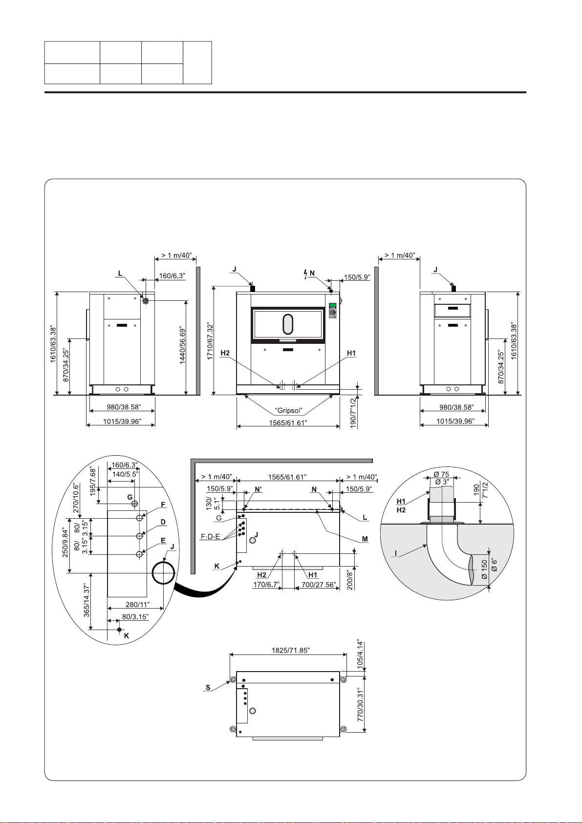
Washer extractor type 250 standard Diagram no. 07100081B
Heating Gas Electric Steam Thermic fl uid
Characteristics Ø cage ---- ----------------------- 770 mm (30.31") -----------------
Cage length ---- ----------------------- 520 mm (20.47") ---------------- Cage volume ----------------------- 229 dm³ (229 l) ----------------- Specifi c load 1/10 ---- ------------------------- 22.9 kg (50.5 lb) -------------- (dry linen, ISO 9398-4)
Opening cage doors (L x H) ---- ------------- 450 x 400 mm (17.71x15.74") --------- Opening drum door (L x H) ----- ------------- 466 x 525 mm (18.34x20.67") ----------
Floor area ---- ----------------------- 1 m² (10.76 sq. ft) ---------------
Net weight ---- ----------------------- 670 daN (1478 lb) --------------Weight loaded (high level) ---- ----------------------- 830 daN (1830 lb) --------------Water volume, washing, low level 68 l 68l 68 l 68 l
Water volume, washing, high level 137 l 137 l 137 l 137 l
Max dynamic load ---- ----------------- F = 101 daN (222 lb) ----------------Max transmitted fl oor load ---- ------------------- 814 daN (1795 lb) ------------------Max pressure transmitted to fl oor ---- ------------------- 100 kPa ------------------------------Spin effi ciency ---- ------------------------------ 350 G ----------------------Max. unbalance ---- ----------------------- 3.6 kg (7.94 lb) ------------------
(L) Main switch to connect main cable
(M) Electric cable (section) 4x2.5 mm² 4x6 mm² 4x2.5 mm² 4x2.5 mm²
(N) or (N') Stuffi ng box for main cable
Supply voltage --------- ----------------380 / 415 V 3+E ~ 50/60 Hz----------Installed electric power 3.7 kW 21.7 kW 3.7 kW 3.7 kW
Installed heating power 40 kW 18 kW - Electric consumption for a normal cycle* 0.8 kWh/h 6 kWh/h 0.6 kWh/h 0.6 kWh/h
Heat loss --------- ----------3 % of installed heating power-------------
(G) Steam inlet Standard : DN 20 (3/4" BSP) Low pressure : DN 25 (1" BSP)
- Maximum supply pressure 600 kPa (87 psi)
- Steam intantaneous fl ow rate at 600 kPa 72 kg/h
- Seam consumption for a normal cycle* 12 kg/h at 600 kPa (87 psi)
(D) Hot water connection / fl ow DN 20 (3/4" BSP) - 70 l/min at 250 kPA (36 psi)
(E) Cold hard water connection / fl ow DN 20 (3/4" BSP) - 70 l/min at 250 kPA (36 psi)
(F) Cold soft water connection / fl ow (option) DN 20 (3/4" BSP) - 70 l/min at 250 kPA (36 psi)
Water supply minimum pressure --- ------------------------ 50 kPa (7.25 psi) --------------Water supply maximum pressure --- ------------------------ 300 kPa (43.5 psi) ------------Water consumption for a normal cycle* 360 l 340 l 340 l 340 l
Water consumption for an ECO cycle** 282 l 260 l 260 l 260 l
(K) Liquid detergents inlet DN 20 (3/4" BSP)
(H1) Drain connection --- ------------------------ Ø 75 mm (3") -------------------(H2) Double drain connection ---
Maximum fl ow rate ---- -------------------------- 240 l/min ----------------------(I) Waste water collector ---- -------------------- DN 150 mm (6" BSP) --------------
(3 cm/m (3%) minimum slope)
(J) Air vent hole ---- -------------------- Ø 60 mm (2.36 ") ------------------(N') Thermic fl uid inlet or indirect steam heating DN 15 (1/2" BSP)
(G) Thermic fl uid return or indirect steam heating DN 15 (1/2" BSP)
- Maximum supply pressure 600 kPa
- Installed calorifi c power 34400 kcal
- Average calorifi c consumption 11500 kcal/h
- Inner volume thermic fl uid exchanger 2,62 l
Gas inlet DN 20 (3/4" BSP)
Combustion products evacuation Ø 125 mm (5")
(S) Weighing equipment (optional)
Compressed air inlet (low pressure steam) ---------------------------Ø 4/6 mm-----------------------------
- Min./max. compress air pressure -------------------5,5/7 bar--------------------------------
- Consumption --------------------------------10 l/h-----------------------------
* normal cycle : prewash 3 min at 35 °C, drain. 2 min, main wash 4 min at 65 °C, drain 2 min, rinse 2 min, extract. 2 min, rinse 2 min, extract 2 min, rinse 2 min, extrac. 10 min (cold water supply at 15 °C).
** ECO cycle : normal cycle with rinse 5 l/kg instead of 6 l/kg dry linen.
------------------------ Ø 75 mm (3") --------------------
Page 20

01201138
0408 3
8.Technical
8
Notice
Date
Washer extractor type 350 standard
Page
characteristics
Front viewRight view Left view
INSTRUCTION
HANDBOOK
Top view
Drain connection
07100083B
Page 21

INSTRUCTION
HANDBOOK
8.Technical
characteristics
01201138
Notice
0208 4
Date
Page
8
Washer extractor type 350 standard Diagram n°. 07100083B
Heating Gas Electric Steam Thermic fl uid
Characteristics Ø cage ---- ----------------------- 770 mm (30.31") -----------------
Cage length ---- ------------------------- 760 mm (30") ------------------ Cage voume ----------------------- 338 dm³ (338 l) ----------------- Specifi c load 1/10 ---- ------------------------- 33.8 kg (74.55 lb) ------------ (dry linen, ISO 9398-4)
Opening cage doors (L x H) ---- ------------- 600 x 400 mm (23.62x15.74") --------- Opening drum door (L x H) ----- ------------- 616 x 525 mm (24.25x20.67") ----------
Floor area ---- -------------------- 1.25 m² (13.45 sq. ft) --------------
Net weight ---- ----------------------- 760 daN (1676 lb) --------------Weight loaded (high level) ---- ---------------------- 996 daN (2195 lb) -------------Water, washing, low level 101 l 101 l 101 l 101 l
Water, washing, high level 202 l 202 l 202 l 202 l
Max dynamic load ---- ----------------- F = 155 daN (342 lb) -----------------Max transmitted fl oor load ---- ------------------- 800 daN (1764 lb) ----------------Max pressure transmitted to fl oor ---- ------------------- 120 kPa ------------------------------Spin effi ciency ---- ------------------------------ 350 G ----------------------Max. unbalance ---- ----------------------- 4.8 kg (10.58 lb) -----------------
(L) Main switch to connect main cable
(M) Electric cable (section) 4x2.5 mm² 4x16 mm² 4x2.5 mm² 4x2.5 mm²
(N) or (N') Stuffi ng box for main cable
Supply voltage --------- ----------------380 / 415 V 3+E ~ 50/60 Hz----------Installed electric power 4.8 kW 32 kW 4.8 kW 4.8 kW
Installed heating power 40 kW 27 kW - Electrical consumption for a normal cycle* 1.2 kWh/h 9.2 kWh/h 1 kWh/h 1 kWh/h
Heat loss --------- ----------3 % of installed heating power--------------
(G) Steam inlet Standard : DN 20 (3/4" BSP) Low pressure : DN 25 (1" BSP)
- Maximum supply pressure 600 kPa (87 psi)
- Steam instantaneous fl ow rate at 600 kPa 108 kg/h
- Steam consumption for a normal cycle* 18 kg/h at 600 kPa (87 psi)
(D) Hot water connection / fl ow DN 20 (3/4" BSP) - 70 l/min at 250 kPA (36 psi)
(E) Cold hard water connection / fl ow DN 20 (3/4" BSP) - 70 l/min at 250 kPA (36 psi)
(F) Cold soft water connection / fl ow (option) DN 20 (3/4" BSP) - 70 l/min at 250 kPA (36 psi)
Water supply minimum pressure --- ------------------------ 50 kPa (7.25 psi) --------------Water supply maximum pressure --- ------------------------ 300 kPa (43.5 psi) -------------Water consumption for a normal cycle* 495 l 470 l 470 l 470 l
Water consumption for a ECO cycle** 415 l 395 l 395 l 395 l
(K) Liquid detergents inlet DN 20 (3/4" BSP)
(H1) Drain connection --- ------------------------ Ø 75 mm (3") -------------------(H2) Double drain connection ---
Maximum drain fl ow rate 240 l/min 240 l/min 240 l/min 240 l/min
(I) Waste water collector ---- -------------------- DN 150 mm (6" BSP) ---------------
(3 cm/m (3 %) minimum slope)
(J) Air vent hole ---- -------------------- Ø 60 mm (2.36 ") ------------------(N') Thermic fl uid inlet or indirect steam heating DN 15 (1/2" BSP)
(G) Thermic fl uid return or indirect steam heating DN 15 (1/2" BSP)
- Maximum supply pressure. 600 kPa
- Installed calorifi c power 34400 kcal
- Average calorifi c consumption 12500 kcal/h
- Inner volume thermic fl uid 2,62 l
Gas inlet DN 20 (3/4" BSP)
Combustion products evacuation Ø 125 mm (5")
(S) Weighing equipment (optional)
Compressed air inlet (low pressure steam) ---------------------------Ø 4/6 mm-----------------------------
- Min./max. compress air pressure -------------------5,5/7 bar--------------------------------
- Consumption --------------------------------10 l/h-----------------------------
* normal cycle : prewash 3 min at 35 °C, drain. 2 min, main wash 4 min at 65 °C, drain 2 min, rinse 2 min, extract. 2 min, rinse 2 min, extract 2 min, rinse 2 min, extrac. 10 min (cold water supply at 15 °C).
** ECO cycle : normal cycle with rinse 5 l/kg instead of 6 l/kg dry linen.
------------------------ Ø 75 mm (3") --------------------
Page 22
01201138
0408 5
8.Technical
8
Notice
Date
Washer extractor type 500 standard
Page
characteristics
Front viewRight view Left view
INSTRUCTION
HANDBOOK
Top view
Drain connection
07100085B
Page 23

INSTRUCTION
HANDBOOK
8.Technical
characteristics
01201138
Notice
0208 6
Date
Page
8
Washer extractor type 500 standard Diagram no. 07100085B
Heating Gas Electric Steam Thermic fl uid
Characteristics Ø cage ---- ----------------------- 770 mm (30.31") -----------------
Cage length ---- ------------------------- 1040 mm (41") ---------------- Cage volume ----------------------- 467 dm³ (467 l) ----------------- Specifi c load 1/10 ---- ----------------------- 46.7 kg (103 lb) ----------------- (dry linen, ISO 9398-4)
Opening cage doors (L x H) ---- ------------ 2x450 x 400 mm (17.71x15.74") -------- Opening drum door (L x H) ----- ------------- 935 x 527 mm (36.81x20.74") ----------
Floor area ---- -------------------- 1.52 m² (16.36 sq. ft) --------------
Net weight ---- ----------------------- 920 daN (2028 lb) --------------Weight loaded (high level) ---- ----------------------- 1247 daN (2750 lb) ------------Water, washing, low level 140 l 140 l 140 l 140 l
Water, washing, high level 180 l 180 l 180 l 180 l
Max dynamic load ---- ----------------- F = 275 daN (606 lb) -----------------Max transmitted fl oor load ---- ------------------- 830 daN (1830 lb) ----------------Max pressure transmitted to fl oor ---- ------------------- 150 kPa ------------------------------Spin effi ciency ---- ------------------------------ 350 G ----------------------Max. unbalance ---- ----------------------- 5.5 kg (12.13 lb) -----------------
(L) Main switch to connect main cable
(M) Electric cable (section) 4x2.5 mm² 4x25 mm² 4x2.5 mm² 4x2.5 mm²
(N) or (N') Stuffi ng box for main cable
Supply voltage --------- ----------------380 / 415 V 3+E ~ 50/60 Hz----------Installed electric power 5.8 kW 42 kW 5.8 kW 5.8 kW
Installed heating power 40 kW 36 kW - Electrical consumption for a normal cycle* 1.5 kWh/h 11 kWh/h 1.2 kWh/h 1.2 kWh/h
Heat loss --------- ----------3 % of installed heating power--------------
(G) Steam inlet Standard : DN 20 (3/4" BSP) Low pressure : DN 25 (1" BSP)
- Maximum supply pressure 600 kPa (87 psi)
- Steam instantaneous fl ow rate at 600 kPa 144 kg/h
- Steam consumption for a normal cycle* 24.5 kg/h at 600 kPa (87 psi)
(D) Hot water connection / fl ow DN 20 (3/4" BSP) - 70 l/min at 250 kPA (36 psi)
(E) Cold hard water connection / fl ow DN 20 (3/4" BSP) - 70 l/min at 250 kPA (36 psi)
(F) Cold soft water connection / fl ow (option) DN 20 (3/4" BSP) - 70 l/min at 250 kPA (36 psi)
Water supply minimum pressure --- ------------------------ 50 kPa (7.25 psi) --------------Water supply maximum pressure --- ------------------------ 300 kPa (43.5 psi) -------------Water consumption for a normal cycle* 638 l 610 l 610 l 610 l
Water consumption for an ECO cycle** 558 l 530 l 530 l 530 l
(K) Liquid detergents inlet DN 20 (3/4" BSP)
(H1) Drain connection --- ------------------------ Ø 75 mm (3") -------------------(H2) Double drain connection ---
Maximum drain fl ow rate 240 l/min 240 l/min 240 l/min 240 l/min
(I) Waste water collector ---- -------------------- DN 150 mm (6" BSP) ---------------
(3 cm/m (3 %) minimum slope)
(J) Air vent hole ---- -------------------- Ø 60 mm (2.36 ") ------------------(N') Thermic fl uid inlet or indirect steam heating DN 15 (1/2" BSP)
(G) Thermic fl uid return or indirect steam heating DN 15 (1/2" BSP)
- Maximum supply pressure 600 kPa
- Installed calorifi c power 47300 kcal
- Average calorifi c consumption 13800 kcal/h
- Inner volume thermic fl uid 5,33 l
Gas inlet DN 20 (3/4" BSP)
Combustion products evacuation Ø 125 mm (5")
(S) Weighing equipment (optional)
Compressed air inlet (low pressure steam) ---------------------------Ø 4/6 mm-----------------------------
- Min./max. compress air pressure -------------------5,5/7 bar--------------------------------
- Consumption --------------------------------10 l/h-----------------------------
* normal cycle : prewash 3 min at 35 °C, drain. 2 min, main wash 4 min at 65 °C, drain 2 min, rinse 2 min, extract. 2 min, rinse 2 min, extract 2 min, rinse 2 min, extrac. 10 min (cold water supply at 15 °C).
** ECO cycle : normal cycle with rinse 5 l/kg instead of 6 l/kg dry linen.
------------------------ Ø 75 mm (3") --------------------
Page 24

01201138
1009 7
8.Technical
8
Notice
Date
Washer extractor type 650 standard
Page
characteristics
Front viewRight view Left view
INSTRUCTION
HANDBOOK
Top view
Drain connection
07100087B
Page 25

INSTRUCTION
HANDBOOK
8.Technical
characteristics
01201138
Notice
0208 8
Date
Page
8
Washer extractor type 650 standard Diagram no. 07100087B
Heating Gas Electric Steam Thermic fl uid
Characteristics Ø cage ---- ----------------------- 770 mm (30.31") -----------------
Cage length ---- ------------------------- 1500 mm (59") ---------------- Cage volume ----------------------- 668 dm³ (668 l) ----------------- Specifi c load 1/10 ---- ----------------------- 66.8 kg (147.33 lb) ------------- (dry linen, ISO 9398-4)
Opening cage doors (L x H) ---- ------------ 2x600 x 400 mm (23.62x15.74") -------- Opening drum door (L x H) ----- ---------- 2x616 x 525 mm (24.25x20.66") ---------
Floor area ---- -------------------- 2 m² (21.53 sq. ft) ------------------
Net weight ---- ----------------------- 1080 daN (2381 lb) --------------Weight loaded (high level) ---- -----------------------1547 daN (3410 lb) -------------Water, washing, low level 200 l 200 l 200 l 200 l
Water, washing, high level 400 l 400 l 400 l 400 l
Max dynamic load ---- ----------------- F = 466 daN (1028 lb) ---------------Max transmitted fl oor load ---- -------------------- 811 daN (1788 lb) ---------------Max pressure transmitted to fl oor ---- -------------------- 187 kPa -----------------------------Spin effi ciency ---- ------------------------------ 350 G ----------------------Max. unbalance ---- ----------------------- 8 kg (17.65 lb) -------------------
(L) Main switch to connect main cable
(M) Electric cable (section) 4x2.5 mm² 4x35 mm² 4x2.5 mm² 4x2.5 mm²
(N) or (N') Stuffi ng box for main cable
Supply voltage --------- ----------------380 / 415 V 3+E ~ 50/60 Hz----------Installed electric power 7.8 kW 61.5 kW 7.8 kW 7.8 kW
Installed heating power 40 kW 54 kW - Electrical consumption for a normal cycle* 2 kWh/h 23 kWh/h 2 kWh/h 2 kWh/h
Heat loss --------- ----------3 % of installed heating power--------------
(G) Steam inlet Standard : DN 20 (3/4" BSP) Low pressure : DN 25 (1" BSP)
- Maximum supply pressure 600 kPa (87 psi)
- Steam instantaneous fl ow rate at 600 kPa 216 kg/h
- Steam consumption for a normal cycle* 24.5 kg/h at 600 kPa (87 psi)
(D) Hot water connection / fl ow DN 20 (3/4" BSP) - 70 l/min at 250 kPA (36 psi)
(E) Cold hard water connection / fl ow DN 20 (3/4" BSP) - 70 l/min at 250 kPA (36 psi)
(F) Cold soft water connection / fl ow (option) DN 20 (3/4" BSP) - 70 l/min at 250 kPA (36 psi)
Water supply minimum pressure --- ------------------------ 50 kPa (7.25 psi) --------------Water supply maximum pressure --- ------------------------ 300 kPa (43.5 psi) -------------Water consumption for a normal cycle* 977 l 977 l 977 l 977 l
Water consumption for an ECO cycle** 782 l 782 l 782 l 782 l
(K) Liquid detergents inlet DN 20 (3/4" BSP)
(H1) Drain connection --- ------------------------ Ø 75 mm (3") -------------------(H2) Double drain connection --- ------------------------ Ø 75 mm (3") -------------------Maximum drain fl ow rate 240 l/min 240 l/min 240 l/min 240 l/min
(I) Waste water collector ---- -------------------- DN 150 mm (6" BSP) ---------------
(3 cm/m (3 %) minimum slope)
(J) Air vent hole ---- -------------------- Ø 60 mm (2.36 ") ------------------(N') Thermic fl uid inlet or indirect steam heating DN 15 (1/2" BSP)
(G) Thermic fl uid return or indirect steam heating DN 15 (1/2" BSP)
- Maximum supply pressure 600 kPa
- Installed calorifi c power 47300 kcal
- Average calorifi c consumption 15800 kcal/h
- Inner volume thermic fl uid 5,33 l
Gas inlet DN 20 (3/4" BSP)
Combustion products evacuation Ø 125 mm (5")
(S) Weighing equipment (optional)
Compressed air inlet (low pressure steam) ---------------------------Ø 4/6 mm-----------------------------
- Min./max. compress air pressure -------------------5,5/7 bar--------------------------------
- Consumption --------------------------------10 l/h-----------------------------
* normal cycle : prewash 3 min at 35 °C, drain. 2 min, main wash 4 min at 65 °C, drain 2 min, rinse 2 min, extract. 2 min, rinse 2 min, extract 2 min, rinse 2 min, extrac. 10 min (cold water supply at 15 °C).
** ECO cycle : normal cycle with rinse 5 l/kg instead of 6 l/kg dry linen.
Page 26

01201138
0408 9
8
Notice
Date
Washer extractor type 250 barrier
Page
characteristics
Front viewRight view Left view
8.Technical
INSTRUCTION
HANDBOOK
Top view
Drain connection
07100082B
Page 27

INSTRUCTION
HANDBOOK
8.Technical
characteristics
01201138
Notice
0208 10
Date
Page
8
Washer extractor type 250 barrier Diagram no. 07100082B
Heating Gas Electric Steam Thermic fl uid
Characteristics Ø cage --------------------- 770 mm (30.31") ---------------------
Cage length --------------------- 520 mm (20.47") ------------------ Cage volume ---------------------- 229 dm³ (229 l) -------------------- Specifi c load 1/10 -------------------- 22.9 kg (50.5 lb) ------------------ (dry linen, ISO 9398-4)
Opening cage doors (L x H) ----------- 450 x 400 mm (17.71x15.74") ------------ Opening drum door (L x H) ----------- 466 x 525 mm (18.34x20.67") -------------
Floor area ------------------- 1 m² (10.76 sq. ft) ------------------Net weight --------------------- 670 daN (1478 lb) ------------------Weight loaded (high level) --------------------- 830 daN (1830 lb) ------------------Water, washing, low level 68 l 68 l 68 l 68 l
Water, washing, high level 137 l 137 l 137 l 137 l
Max dynamic load ---------------------- F = 101 daN (222 lb) ------------------Max transmitted fl oor load ----------------------- 814 daN (1795 lb) --------------------Max pressure transmitted to fl oor ----------------------- 100 kPa ---------------------------------Spin effi ciency ------------------------------- 350 G ----------------------------Max. unbalance ----------------------------- 3.6 kg (7.94 lb) -------------------
(L) Main switch to connect main cable
(M) Electric cable (section) 4x2.5 mm² 4x6 mm² 4x2.5 mm² 4x2.5 mm²
(N) or (N') Stuffi ng box for main cable
Supply voltage --------- ----------------380 / 415 V 3+E ~ 50/60 Hz----------Installed electric power 3.7 kW 21.70 kW 3.7 kW 3.7 kW
Installed heating power 40 kW 18 kW - Electrical consumption for a normal cycle* 0.8 kWh/h 5.3 kWh/h 0.6 kWh/h 0.6 kWh/h
Heat loss --------- ----------3 % of installed heating power--------------
(G) Steam inlet Standard : DN 20 (3/4" BSP) Low pressure : DN 25 (1" BSP)
- Maximum supply pressure 600 kPa (87 psi)
- Steam instantaneous fl ow rate at 600 kPa 72 kg/h
- Steam consumption for a a normal cycle* 12 kg/h at 600 kPa (87 psi)
(D) Hot water connection / fl ow DN 20 (3/4" BSP) - 70 l/min at 250 kPA (36 psi)
(E) Cold hard water connection / fl ow DN 20 (3/4" BSP) - 70 l/min at 250 kPA (36 psi)
(F) Cold soft water connection / fl ow (option) DN 20 (3/4" BSP) - 70 l/min at 250 kPA (36 psi)
Water supply minimum pressure ---------------------- 50 kPa (7.25 psi) ----------------Water supply maximum pressure ---------------------- 300 kPa (43.5 psi) ---------------Water consumption for a normal cycle* 360 l 340 l 340 l 340 l
Water consumption for an ECO cycle** 282 l 260 l 260 l 260 l
(K) Liquid detergents inlet DN 20 (3/4" BSP)
(H1) Drain connection ------------------------- Ø 75 mm (3") ------------------(H2) Double drain connection ------------------------- Ø 75 mm (3") ------------------Maximum drain fl ow rate 240 l/min 240 l/min 240 l/min 240 l/min
(I) Waste water collector --------------------- DN 150 mm (6" BSP) -------------
(3 cm/m (3 %) minimum slope)
(J) Air vent hole ------------------------ Ø 60 mm (2.36") ---------------(N') Thermic fl uid inlet or indirect steam heating DN 15 (1/2" BSP)
(G) Thermic fl
- Maximum supply pressure 600 kPa
- Installed calorifi c power 34400 kcal
- Average calorifi c consumption 11500 kcal/h
- Inner volume thermic fl uid 2,62 l
Gas inlet DN 20 (3/4" BSP)
Combustion products evacuation Ø 125 mm (5")
(O) Barrier partition (provided by customer)
(P) Frame 60x100 mm maxi (provided by customer)
(R) Aseptis seal
(S) Weighing equipment (optional)
Compressed air inlet (low pressure steam) ---------------------------Ø 4/6 mm-----------------------------
- Min./max. compress air pressure -------------------5,5/7 bar--------------------------------
- Consumption --------------------------------10 l/h-----------------------------
uid return or indirect steam heating DN 15 (1/2" BSP)
* normal cycle : prewash 3 min at 35 °C, drain. 2 min, main wash 4 min at 65 °C, drain 2 min, rinse 2 min, extract. 2 min, rinse 2 min, extract 2 min, rinse 2 min, extrac. 10 min (cold water supply at 15 °C).
** ECO cycle : normal cycle with rinse 5 l/kg instead of 6 l/kg dry linen.
Page 28

01201138
0408 11
8
Notice
Date
Washer extractor type 350 barrier
Page
characteristics
Front viewRight view Left view
8.Technical
INSTRUCTION
HANDBOOK
Top view
Drain connection
07100084B
Page 29

INSTRUCTION
HANDBOOK
8.Technical
characteristics
01201138
Notice
0208 12
Date
Page
8
Washer extractor type 350 barrier Diagram no. 07100084B
Heating Gas Electric Steam Thermic fl uid
Characteristics Ø cage --------------------- 770 mm (30.31") ------------------
Cage lenght ----------------------- 760 mm (30") ------------------ Cage volume ---------------------- 338 dm³ (338 l) ------------------ Specifi c load 1/10 ------------------------ 33.8 kg (74.55 lb) ------------- (dry linen, ISO 9398-4)
Opening cage doors (L x H) -------------- 600 x 400 mm (23.62x15.74") ----------- Opening drum door (L x H) --------------- 616 x 525 mm (24.25x20.67") ------------
Floor area ------------------ 1.25 m² (13.45 sq. ft) ---------------Net weight --------------------- 760 daN (1676 lb) ----------------Weight loaded (high level) -------------------- 996 daN (2195 lb) ---------------Water, washing, low level 101 l 93 l 101 l 101 l
Water, washing, high level 202 l 202 l 202 l 202 l
Max dynamic load -------------------- F = 155 daN (342 lb) -------------Max transmitted fl oor load ---------------------- 800 daN (1764 lb) -------------Max pressure transmitted to fl oor ---------------------- 120 kPa ---------------------------Spin effi ciency ----------------------------- 350 G -----------------------Max. unbalance ------------------------ 4.8 kg (10.58 lb) ----------------
(L) Main switch to connect main cable
(M) Electric cable (section) 4x2.5 mm² 4x16 mm² 4x2.5 mm² 4x2.5 mm²
(N) or (N') Stuffi ng box for main cable
Supply voltage --------- ----------------380 / 415 V 3+E ~ 50/60 Hz----------Installed electric power 4.8 kW 32 kW 4.8 kW 4.8 kW
Installed heating power 40 kW 27 kW - Electrical consumption for a normal cycle* 1.2 kWh/h 9.2 kWh/h 1 kWh/h 1 kWh/h
Heat loss --------- ----------3 % of installed heating power--------------
(G) Steam inlet Standard : DN 20 (3/4" BSP) Low pressure : DN 25 (1" BSP)
- Maximum supply pressure 600 kPa (87 psi)
- Steam instantaneous fl ow rate at 600 kPa 108 kg/h
- Steam consumption for a normal cycle* 18 kg/h at 600 kPa (87 psi)
(D) Hot water connection / fl ow DN 20 (3/4" BSP) - 70 l/min at 250 kPA (36 psi)
(E) Cold hard water connection / fl ow DN 20 (3/4" BSP) - 70 l/min at 250 kPA (36 psi)
(F) Cold soft water connection / fl ow (option) DN 20 (3/4" BSP) - 70 l/min at 250 kPA (36 psi)
Water supply minimum pressure ---------------------- 50 kPa (7.25 psi) ----------------Water supply maximum pressure --------------------- 300 kPa (43.5 psi) ----------------Water consumption for a normal cycle* 495 l 470 l 470 l 470 l
Water consumption for an ECO cycle** 315 l 395 l 395 l 395 l
(K) Liquid detergents inlet DN 20 (3/4" BSP)
(H1) Drain connection ------------------------- Ø 75 mm (3") ------------------(H2) Double drain connection ------------------------- Ø 75 mm (3") ------------------Maximum drain fl ow rate 240 l/min 240 l/min 240 l/min 240 l/min
(I) Waste water collector
(3 cm/m (3 %) minimum slope)
(J) Air vent hole ------------------------ Ø 60 mm (2.36") ---------------(N') Thermic fl uid inlet or indirect steam heating DN 15 (1/2" BSP)
(G) Thermic fl uid return or indirect steam heating DN 15 (1/2" BSP)
- Maximum supply pressure 600 kPa
- Installed calorifi c power 34400 kcal
- Average calorifi c consumption 12500 kcal/h
- Inner volume thermic fl uid 2,62 l
Gas inlet DN 20 (3/4" BSP)
Combustion products evacuation Ø 125 mm (5")
(O) Barrier partition (provided by customer)
(P) Frame 60x100 mm maxi (provided by customer)
(R) Aseptis seal
(S) Weighing equipment (optional)
Compressed air inlet (low pressure steam) ---------------------------Ø 4/6 mm-----------------------------
- Min./max. compress air pressure -------------------5,5/7 bar--------------------------------
- Consumption --------------------------------10 l/h-----------------------------
* normal cycle : prewash 3 min at 35 °C, drain. 2 min, main wash 4 min at 65 °C, drain 2 min, rinse 2 min, extract. 2 min, rinse 2 min, extract 2 min, rinse 2 min, extrac. 10 min (cold water supply at 15 °C).
** ECO cycle : normal cycle with rinse 5 l/kg instead of 6 l/kg dry linen.
--------------------- DN 150 mm (6" BSP) -------------
Page 30

01201138
0408 13
8
Notice
Date
Washer extractor type 500 barrier
Page
characteristics
Front viewRight view Left view
8.Technical
INSTRUCTION
HANDBOOK
Top view
Drain connection
07100086B
Page 31

INSTRUCTION
HANDBOOK
8. Characteristics
techniques
01201138
Notice
0208 14
Date
Page
8
Washer extractor type 500 barrier Diagram no. 07100086B
Heating Gas Electric Steam Thermic
fl uid
Characteristics Ø cage --------------------- 770 mm (30.31") ------------------
Cage length ----------------------- 1040 mm (41") ------------------ Cage volume ---------------------- 467 dm³ (467 l) ------------------ Specifi c load 1/10 ----------------------- 46.7 kg (103 lb) ----------------- (dry linen, ISO 9398-4)
Opening cage doors (L x H) -------------- 2x450 x 400 mm (17.71x15.74") --------- Opening drum door (L x H) ----------------- 935 x 527 mm (36.81x20.74") -----------
Floor area ------------------ 1.52 m² (16.36 sq. ft) ---------------Net weight -------------------- 920 daN (2028 lb) -----------------Weight loaded (high level) -------------------- 1247 daN (2750 lb) ---------------Water, washing, low level 140 l 140 l 140 l 140 l
Water, washing, high level 280 l 280 l 280 l 255 l
Max dynamic load -------------------- F = 275 daN (606 lb) -------------Max transmitted fl oor load ---------------------- 830 daN (1830 lb) -------------Max pressure transmitted to fl oor ---------------------- 150 kPa ---------------------------Spin effi ciency ----------------------------- 350 G -----------------------Max. unbalance ------------------------ 5.5 kg (12.13 lb) ----------------
(L) Main switch to connect main cable
(M) Electric cable (section) 4x2.5 mm² 4x25 mm² 4x2.5 mm² 4x2.5 mm²
(N) or (N') Stuffi ng box for main cable
Supply voltage --------- ----------------380 / 415 V 3+E ~ 50/60 Hz----------Installed electric power 5.8 kW 42 kW 5.8 kW 5.8 kW
Installed heating power 40 kW 36 kW - Electrical consumption for a normal cycle* 1.5 kWh/h 11 kWh/h 1.2 kWh/h 1.2 kWh/h
Heat loss --------- ----------3 % of installed heating power--------------
(G) Steam inlet Standard : DN 20 (3/4" BSP) Low pressure : DN 25 (1" BSP)
- Maximum supply pressure 600 kPa (87 psi)
- Steam instantaneous fl ow rate at 600 kPa 144 kg/h
- Steam consumption for a normal cycle* 24.5 kg/h at 600 kPa (87 psi)
(D) Hot water connection / fl ow DN 20 (3/4" BSP) - 70 l/min at 250 kPA (36 psi)
(E) Cold hard water connection / fl ow DN 20 (3/4" BSP) - 70 l/min at 250 kPA (36 psi)
(F) Cold soft water connection / fl ow (option) DN 20 (3/4" BSP) - 70 l/min at 250 kPA (36 psi)
Water supply minimum pressure ---------------------- 50 kPa (7.25 psi) ----------------Water supply maximum pressure --------------------- 300 kPa (43.5 psi) ----------------Water consumption for a normal cycle* 638 l 610 l 610 l 610 l
Water consumption for an ECO cycle** 558 l 530 l 530 l 530 l
(K) Liquid detergents inlet DN 20 (3/4" BSP)
(H1) Drain connection ------------------------- Ø 75 mm (3") ------------------(H2) Double drain connection ------------------------- Ø 75 mm (3") ------------------Maximum drain fl ow rate 240 l/min 240 l/min 240 l/min 240 l/min
(I) Waste water collector --------------------- DN 150 mm (6" BSP) -------------
(3 cm/m (3 %) minimum slope)
(J) Air vent hole ------------------------ Ø 60 mm (2.36") ---------------(N') Thermic fl uid inlet or indirect steam heating DN 15 (1/2" BSP)
(G) Thermic fl uid return or indirect steam heating DN 15 (1/2" BSP)
- Maximum supply pressure 600 kPa
- Installed calorifi c power 47300 kcal
- Average calorifi c consumption 13800 kcal/h
- Inner volume thermic fl uid 5,33 l
Gas inlet DN 20 (3/4" BSP)
Combustion products evacuation Ø 125 mm (5")
(O) Barrier partition (provided by customer)
(P) Frame 60x100 mm maxi (provided by customer)
(R) Aseptis seal
(S) Weighing equipment (optional)
Compressed air inlet (low pressure steam) ---------------------------Ø 4/6 mm-----------------------------
- Min./max. compress air pressure -------------------5,5/7 bar--------------------------------
- Consumption --------------------------------10 l/h-----------------------------
* normal cycle : prewash 3 min at 35 °C, drain. 2 min, main wash 4 min at 65 °C, drain 2 min, rinse 2 min, extract. 2 min, rinse 2 min, extract 2 min, rinse 2 min, extrac. 10 min (cold water supply at 15 °C).
** ECO cycle : normal cycle with rinse 5 l/kg instead of 6 l/kg dry linen.
Page 32

01201138
1009 15
8
Notice
Date
Washer extractor type 650 barrier
Page
characteristics
Front viewRight view Left view
8.Technical
INSTRUCTION
HANDBOOK
Top view
Drain connection
07100088B
Page 33

INSTRUCTION
HANDBOOK
8.Technical
characteristics
01201138
Notice
0208 16
Date
Page
8
Washer extractor type 650 barrier Diagram no. 07100088B
Heating Gas Electric Steam Thermic fl uid
Characteristics Ø cage --------------------- 770 mm (30.31") ------------------
Cage length ----------------------- 1550 mm (59") ------------------ Cage volume ---------------------- 668 dm³ (668 l) ------------------ Specifi c load 1/10 ----------------------- 66.8 kg (147.33 lb) ------------- (dry linen, ISO 9398-4)
Opening cage doors (L x H) -------------- 2x600 x 400 mm (23.62x15.74") --------- Opening drum door (L x H) --------------- 2x616 x 525 mm (24.25x20.66") ----------
Floor area ------------------ 2 m² (21.53 sq. ft) ------------------
Net weight ------------------- 1080 daN (2380 lb) ------------------Weight loaded (high level) ------------------ 1247 daN (2750 lb) -----------------Water, washing, low level 200 l 200 l 200 l 200 l
Water, washing, high level 400 l 400 l 365 l 400 l
Max dynamic load ------------------ F = 466 daN (1028 lb) --------------Max transmitted fl oor load ---------------------- 811 daN (1788 lb) -------------Max pressure transmitted to fl oor ---------------------- 186 kPa ---------------------------Spin effi ciency ----------------------------- 350 G -----------------------Max. unbalance ------------------------ 8 kg (17.65 lb) ------------------
(L) Main switch to connect main cable
(M) Electric cable (section) 4x2.5 mm² 4x35 mm² 4x2.5 mm² 4x2.5 mm²
(N) or (N') Stuffi ng box for main cable
Supply voltage --------- ----------------380 / 415 V 3+E ~ 50/60 Hz----------Installed electric power 7.8 kW 61.5 kW 7.8 kW 7.8 kW
Installed heating power 40 kW 54 kW - Electrical consumption for a normal cycle* 2 kWh/h 23 kWh/h 2 kWh/h 2 kWh/h
Heat loss --------- ----------3 % of installed heating power--------------
(G) Steam inlet Standard : DN 20 (3/4" BSP) Low pressure : DN 25 (1" BSP)
- Maximum supply pressure 600 kPa (87 psi)
- Steam instantaneous fl ow rate at 600 kPa 216 kg/h
- Steam consumption for a normal cycle* 24.5 kg/h at 600 kPa (87 psi)
(D) Hot water connection / fl ow DN 20 (3/4" BSP) - 70 l/min at 250 kPA (36 psi)
(E) Cold hard water connection / fl ow DN 20 (3/4" BSP) - 70 l/min at 250 kPA (36 psi)
(F) Cold soft water connection / fl ow (option) DN 20 (3/4" BSP) - 70 l/min at 250 kPA (36 psi)
Water supply minimum pressure ---------------------- 50 kPa (7.25 psi) ----------------Water supply maximum pressure --------------------- 300 kPa (43.5 psi) ----------------Water consumption for a normal cycle* 977 l 977 l 977 l 977 l
Water consumption for an ECO cycle** 782 l 782 l 782 l 782 l
(K) Liquid detergents inlet DN 20 (3/4" BSP)
(H1) Drain connection ------------------------- Ø 75 mm (3") ------------------(H2) Double drain connection ------------------------- Ø 75 mm (3") ------------------Maximum drain fl ow rate 240 l/min 240 l/min 240 l/min 240 l/min
(I) Waste water collector --------------------- DN 150 mm (6" BSP) -------------
(3 cm/m (3 %) minimum slope)
(J) Air vent hole ------------------------ Ø 60 mm (2.36") ---------------(N') Thermic fl uid inlet or indirect steam heating DN 15 (1/2" BSP)
(G) Thermic fl uid return or indirect steam heating DN 15 (1/2" BSP)
- Maximum supply pressure 600 kPa
- Installed calorifi c power 47300 kcal
- Average calorifi c consumption 15800 kcal/h
- Inner volume thermic fl uid 5,33 l
Gas inlet DN 20 (3/4" BSP)
Combustion products evacuation Ø 125 mm (5")
(O) Barrier partition (provided by customer)
(P) Frame 60x100 mm maxi (provided by customer)
(R) Aseptis seal
(S) Weighing equipment (optional)
Compressed air inlet (low pressure steam) ---------------------------Ø 4/6 mm-----------------------------
- Min./max. compress air pressure -------------------5,5/7 bar--------------------------------
- Consumption --------------------------------10 l/h-----------------------------
* normal cycle : prewash 3 min at 35 °C, drain. 2 min, main wash 4 min at 65 °C, drain 2 min, rinse 2 min, extract. 2 min, rinse 2 min, extract 2 min, rinse 2 min, extrac. 10 min (cold water supply at 15 °C).
** ECO cycle : normal cycle with rinse 5 l/kg instead of 6 l/kg dry linen.
Page 34

01201138
0107 17
8. Characteristics
8
Notice
Date
Sound level
Airborne noise emitted by the machine
(values established from measurements
made on machine at points A, B, C, and D).
Weighted sound pressure level (A) in dB(A).
Page
techniques
INSTRUCTION
HANDBOOK
D0267
Washer 250 Washer 350 Washer 500 Washer 650
washing / spinning washing / spinning washing / spinning washing / spinning
A 61,5 73,5 60 71.5 61 72 61 72
B 62,5 76 60 75.5 62 74 60 75
C 61,5 73,5 61 75.5 61 72 61 73
D 62,5 76 61.5 72.5 62 74 62 74
Label of energetic performance (gas heating only)
The global output hg of the gas heated washer-extractor is determinated according to a standardised method and shall not be lower than 50 %.
This output minimal level is indicated on the machine's marking by the symbol .
Beyond the output minimal level hereabove specifi ed, a label of energetic performance is given
to the machine according to its global output hg and according to the hereunder chart.
Symbolisation of the label
The indication of the energetic performance of this washer-extractor is of .
Value of the output hg
50 % <= hg < 65 %
65 % <= hg < 80 %
hg >= 80 %
Page 35

01201138
INSTRUCTION
HANDBOOK
You should have found an instruction handbook and keys to open the machine casings, in the
machine.
Depending on its destination, the washer extractor is delivered bare or may be placed on a
transport pallet and/or packed with plastic fi lm.
In some cases, it may be delivered in a crate, or in maritime packing (wood box).
Please refer to the handling chapter in this instruction handbook for a description of handling
operations.
9. Installation
Notice
0408 1
Date
Unpacking
Take off the plastic fi lm or remove the four wood socles with an spanner.
Check that no damage has been caused during transport.
Page
9
Installation
The installation must be done by competent technicians in accordance with local codes and
regulations. When there are not local codes and regulations, the installation must be comply
with European standards applicable.
The machine must be installed on a perfectly even surface, strong and horizontal, capable
resisting to the efforts shown in the technical characteristics.
Adjustment of the machine by addition of level plate should be avoided.
Control the horizontal level using a water level placed on the machine's sole.
Place the washer extractor so that it is easy for the user and the service technician to do
their work.
Leave at leasy 1 m (40") (according to the recommendation in standard EN 60204) between
the machine, a wall or any other machine at the sides.
40"
40"
40"
water
level
water
level
D0621A
Page 36

01201138
Notice
1109 2
Date
Page
9
9. Installation
INSTRUCTION
Working place lighting
The lighting should be designed so as to avoid eye strain for the operator ; it should be uniform
without any glare, and should be suffi cient to detect any hazards.
The average lighting value on the working place recommended by the clothing industry for
inspecting linen is 500 lux.
Whenever possible, the working place should be illuminated by daylight.
Supplies
Take the box placed underneath the drum.
List of accessories provided with each machine:
• 1 instruction handbook + Clarus Control memory card + converter handbook
• 3 keys for frames
• 1 opening drum lever
HANDBOOK
• 2 or 3 stainless steel fl exible pipes DN20 + 2 or 3 fi ber seals
• 2 or 3 waters fi lters
• 1 connection bellow Ø 60 + 1 collar
• 1 durit Ø 75 mm + 1 collar for drain
• 1 connection nozzle
• 2 fi xing dowells
• 2 fi tted safety locks
• 4 "Gripsol" bolsters (see explanation for the setting)
Extra accessories for steam heating machine:
• 1 steam electrovalve (available in the soap box)
• 1 steam fl exible + 1 steam fi lter
• 1 insulating
Extra accessories for gas heating machine:
• 4 meters blue fl exible pipes
• 2 pipes Ø 125 mm (5") , length 500 mm (20") to be connect at the chimney
• 1 T-square pipe Ø 125 mm (5") and a anti-bursting chimney regulator to be connected over
the gas exchanger
• 1 draught accelerator to extract the exhaust of burn gas, to be connected at the chimney
( in 3 parts)
• 4 collars Ø 40 x 60
Extra accessories for barrier machine:
• 1 rubber seal + the aluminium extruded sections
• 2 fi lling angles + 4 screws + 4 nuts Ø 6
Page 37

INSTRUCTION
HANDBOOK
9. Installation
Mechanical installation
Setting of the "Gripsol" bolsters
Preparation of the ground and machine :
- Degrease carefully the ground and the soles of the machine.
Preparation of the "Gripsol" bolsters :
- Soak the bolsters in hot water during 5 minutes, then let them in open air for 3 to 4
minutes.
- Then unstick the protective fi lm on the two adhesive sides.
Setting the "Gripsol" bolsters :
- Place each bolster (G) at its respective location (see drawing). Check that the bolster
projects inside the soles and heave successively each bearing of the machine.
01201138
Notice
0107 3
Date
Page
9
Putting the machine into service
- Waiting time : Before putting the machine into service, it is necessary that each bearing
is well fi xed by crushing of the upper layer of "Gripsol" and that the lower layer has
penetrated in the porosity of the ground.
For an ambient temperature of 18 °C (65 °F), the crushing time is two hours.
Electrical safety device :
- As "Gripsol" is a very good electric insulating material, the earthing of the machine is
compulsory.
To displace the machines sealed with "Gripsol" bolsters, you just have to heave the machine
and pull off the "Gripsol" bolsters.
D0622A
Page 38

01201138
Notice
0107 4
Date
Page
9
9. Installation
INSTRUCTION
Instructions to fi t the safety fl anges
Position the safety fl anges (A) crosswise (one in the front and the other at the back of the sole).
Mark the place of the drilling hole for the fi xing pin (B) and drill the holes for fi xing of fl anges
(holes diam. 12 mm (1/2"), depth 60 mm (3")).
Put the pins in the fl anges, position the fl anges and screw.
HANDBOOK
D0697A
Page 39

INSTRUCTION
HANDBOOK
9. Installation
01201138
Notice
0107 5
Date
Page
Instructions to fi t the fi lling angles (barrier machines only)
Two angles (A and B) allow to fi ll the the soles ends.
Assemble each fi lling angle with screws and nuts to the sole ends which are next to the
partition wall, in the clean area.
9
D0696A
Page 40

01201138
1009 6
9
Notice
Date
Instructions de pose des dynamomètres
Sur les machines équipées d'un système de pesage, le montage des dynamomètres sur les
types 250, 350 et 500 est en "O" (voir schéma A).
Pour éviter des effets sonores indésirables et des vibrations importantes, le montage sur les
machines type 650 sera en "X" (voir schéma B).
Page
9. Installation
INSTRUCTION
HANDBOOK
A
B
D1798
D1799
Page 41

INSTRUCTION
HANDBOOK
9. Installation
01201138
Notice
1009 7
Date
Page
9
This page ist left blank on purpose.
Page 42

01201138
Notice
0107 8
Date
Page
9
9. Installation
INSTRUCTION
HANDBOOK
Instructions for installation of the washer with barrier partition
The barrier partition (O) (provided by customer) should be assembled before the installation of
the machine.
Centre and align the washer-extractor with the frame (P) 60 x 100 mm maxi (provided by customer).
Place the rubber seal (R) inside the aluminium extruded section (S).
Srew the aluminium extruded section (S) on the frame or on the optional plates (P).
Machine type 250 350 500 650
Size A 1125/44.29 1365/53.74 1645/64.76 2080/81.89
Size B 1650/64.96 1650/64.96 1650/64.96 1650/64.96
Size C 1610/63.38 1610/63.38 1610/63.38 1610/63.38
Size D 1045/41.14 1285/50.39 1565/61.61 2000/78.74
D0582B
Page 43

INSTRUCTION
HANDBOOK
9. Installation
01201138
Notice
0107 9
Date
Waters connections
Washer extractors are assembled in standard execution with two waters inlet.
One hot water and one hard water. On option, a third water inlet (soft) is possible.
The hereunder example sketch shows the connection of the machine to the different inlets.
U Manual stop valve DN 20 (¾" BSP)
(provided by customer)
X Nipple (male) ¾" (provided)
Y Flexible pipe DN 20 (¾" BSP) (provid-
ed)
D Hot water inlet DN 20 (¾" BSP)
E Hard water inlet DN 20 (¾" BSP)
9
Page
F Cold soft water inlet (option) DN 20 (¾"
BSP)
C Steam electrovalve DN20 (¾" BSP)
(provided)
B Water fi lter (provided)
A Washer-extractor
Water supply pressure, 50 kPa (7.25 psi)
mini.
Water supply pressure , 300 kPa (43.5 psi)
maxi.
D0577A
Page 44

01201138
Notice
1008 10
Date
Page
9
9. Installation
INSTRUCTION
Steam connection
For transport reasons, the steam electrovalve is dismantled and placed in the cardboard box
supplies.
The inlet pipe to the machine has to be fi t with a manual stopping valve to ease installation and
maintenance.
Connect the steam electrovalve on its pipe
union.
Assemble the set (P.G.F.V.U) between the
machine and steam piping.
Hereunder values apply to the steam
pressure :
HANDBOOK
Recommended pressure : 300 at 600 kPa
(3 at 6 kg/cm²) (43.5 at 87 psi)
Limiting of values :
mini. 100 kPa (1 kg/cm²) (14.5 psi)
maxi. 600 kPa (6 kg/cm²) (87psi)
Connection size : DN 20 (¾" BSP).
Connect the steam installation on the top of
the machine (see example sketch).
A Washer-extractor
S Steam inlet
Y Manual stop wheel valve DN 20 (¾"
BSP) (provided by customer)
P Steam special fl exible pipe DN 20 (¾"
BSP)(provided)
G Nipple DN 20 (¾" BSP) (provided by
customer)
D1680
Steam set
F Steam fi lter DN 20 (¾" BSP) (provided)
V Steam electrovalve DN 20 (¾" BSP)
(provided)
U Pipe union DN 20 (¾" BSP) (provided)
M Isulating (provided)
D1679
Page 45

INSTRUCTION
HANDBOOK
9. Installation
01201138
Notice
1107 11
Date
Page
Steam and condensate connections: indirect steam heating
Steam connection
The customer must install a line purge, a manually closing valve with handwheel lockable in off
position (do not use a 1/4 turn valve) and a fi lter on the supply side of the washer-extractor.
Hereunder values apply to the steam pressure.
Recommended pressure : 300 at 600 kPa (3 at 6 kg/cm²) (43.5 at 87 psi)
Limiting of values :
•
mini. 100 kPa (1 kg/cm²) (14.5 psi)
•
maxi. 600 kPa (6 kg/cm²) (87psi)
Connection size : DN 15 (½" BSP).
Condensate connection
9
The customer must install a steam trap with fl oat closed with an incondensibles drainage
device, a by-pass, a non-return valve and a manual closing valve lockable in off position (do not
use a 1/4 turn valve).
Connection size : DN 15 (½" BSP).
Connect the steam installation on the top of
the machine (see example sketch).
A Washer-extractor
B Line trap (provided by customer)
C Return of condensates
D Manual stop wheel valve (provided
by customer)
E Steam fi lter (provided by customer)
F Steam trap (provided)
H Non-return valve (provided
by customer)
M Pressure gauge (provided
by customer)
N Thermal insulation for the pipework
(provided by customer)
P Steam electrovalve (provided)
S Safety valve (provided by customer)
V Steam inlet
D1524
Page 46

01201138
0408 12
9
Notice
Date
Drain connection
The machine's exhaust sleeve outside diameter is of 75 mm (3"). It is located underneath the
machine.
The waste water collector diameter 150 mm (6") (manufactured by customer) should have a 3
cm/m (3 %) slope and resist to a temperature of 90 °C (194 °F). It should be connected to the
waste water general network in accordance with local codes and regulations.
Adapt and connect the machine's exhaust sleeve to the waste waters' collector (rubber bend
and connection nozzle are supplied in the machine with collars).
Beside drain kit
The reference of the existing beside drain connection kit is (technical data 31105161) :
Page
9. Installation
INSTRUCTION
HANDBOOK
- 55013696 + 75015189 for the WSB4 250H
and WSB4 350H machines
- 55013697 + 75015189 for the WSB4 500H
and WSB4 650H machines
Drawing of drain connection to waste waters' collector
Connect the durit to the connect nozzle.
Seal and fi x the nozzle using 2 screws.
Them connect the durit to the drain's evacuation sleeve.
Drain's evacuation sleeve
Connection durit
D1591
Connection nozzle
Waste water collector
D1613
Page 47

INSTRUCTION
HANDBOOK
9. Installation
Air vent connection
The air vent of the drum opens on the top of
the machine. Connect the connection bellow
Ø 60 to this opening.
Connect the air vent, to the outside of the
laundry in accordance with tte legislation.
The air vent should resist to 100°C (212°F)
temperature and allow the condenses to
return to the machine.
01201138
Notice
0110 13
Date
Page
Air vent
9
Installation of the gas exchanger
The gas exchanger can be installed indifferently on the left or on the right of the machine according to the available place. Holes are provided on the sole of the machine on the two sides.
CAUTION
The machine should be installed in conformity with the regulations and
standards enforced and situated in a correctly ventilated room.
D0625B
SAFETY
Any repairing or maintenance operation should be carried out by a
specialist.
Page 48

01201138
0107 14
9
Notice
Machine type Units
A Length of exchanger mm/inch 1110/43.7"
B Dimension of output exchanger mm/inch 1040/41"
C Dimension of evacuation pipe mm/inch 645/25.39"
D Evacuation of burn gas mm/inch Ø 125/5"
E Exchanger bottom output mm/inch Ø 36/40 (1"1/2)
F Exchanger bottom input mm/inch Ø 36/40 (1"1/2)
G Gas connection mm/inch DN 20 (3/4" BSP)
W Filter
X Input machine/exchanger ( higher plug on the tank)
Y Output machine/exchanger (lower plug on the tank)
Z Hole for electric cable to gas exchanger
Date
Page
9. Installation
INSTRUCTION
HANDBOOK
The gas exchanger pump must always be connected to the lower plug on the
tank.
Side view
Top view
Front view
D0651A
Page 49

INSTRUCTION
HANDBOOK
9. Installation
01201138
Notice
0107 15
Date
Connection of the evacuation pipe of the gas exchanger.
Fresh air inlet
To allow the gas exchanger to work at ist
best, it is important that the laundry air
inlet passes throught an opening from the
outside.
The fresh air arrival must be equivalent to
the volume of evacuated air.
In order to prevent drafts in the room, the
best solution is to place the air inlet behind
the machine.
It is essential that the rooms should be
ventilated.
The free section of the air inlet must be fi ve
times greater than the section of the evacuation pipe.
9
Page
D0460
Do not forget to allow for the fact that grills often occupy half the total area of the free air
opening.
Evacuation duct
It is recommended that a separate smoothwalled evacuation duct should be connected to each
machine, providing the least possible resistance to air.
Check that the shaft fl ow is at least twice the capacity of the gas exchanger draught
accelerator.
Draught accelerator maximum fl ow rate with no pressure : 260 m³/h (152 cfm).
•
Maximum pressure available with no fl ow : 27 mm H
•
•
Maximum admissible head loss on evacuation : 15 mm H
•
Average temperature of exhaust coming out of the gas exchanger : 140°C (284°F).
Provided an upper ventilation of 7 dm² (1.1 sq. ft) and a lower one of 14 dm² (1.5 sq. ft) in
your laundry.
These conditions are absolutely essential for the correct working of the machine.
For gas heating, the required combustion fresh air supply should be not less than 2 m
cfm) per kW, either 80 m
3
/h (47 cfm) minimum.
O (1" H2O).
2
O (0.6 " H2O) at point (P).
2
3
/h (1.17
NOTE : if the fl ow is insuffi cient due to an excessive pressure loss, a safety pressure switch
will automatically switch the heating off.
Page 50

01201138
0107 16
9
Notice
Date
Installation of the exhaust of
burn gas
Connect the whole set of pipes on your
cheminey pipe, that is to say :
•
1 aluminium pipe (A) lenght 500 mm
(20") on the exchanger.
•
1 T-square (B) pipe + 1 regulator (C).
•
1 aluminium pipe (A) length 500 mm
(20") .
•
1 draught accelerator (D).
It is necessary to install the gas exchanger at the ground level.
Page
9. Installation
INSTRUCTION
HANDBOOK
Evacuation of burn gas from a machine with gas heating must never be
connected to the evacuation used for a dry cleaning machine or other machine of the same type.
Installation of the chemney regulator
For a correct running of the installation, this
chimney regulator must always have its axle
of rotation of his fl ap perfectly horizontal.
The adjustment toothed wheel has to be
positioned on the mark no 7.
D0693A
D0435
Page 51

INSTRUCTION
HANDBOOK
9. Installation
01201138
Notice
0107 17
Date
Gas connection
CAUTION
The installation, connection and gas arrival adjustments for the machine
must be done by qualifi ed personnel only.
The customer must install a fi lter and a manual stop valve on the supply side of the machine if NATURAL GAS is used.
For BUTANE 28-30 mbar or PROPANE 37 or 50 mbar, the customer must install a fi lter, a
manual closing valve and a pressure reducer.
Check that the diameter of injectors is adequate for the king of gas of your installation (see
table). The machine is delivered with extra injectors in a plastic envelope. There is also a sheet
metal plate with a cork joint or an adjusting head to feed the machine with another gas.
Page
9
Connect the installation at the exchanger : DN 20 (3/4" BSP).
A : gas burner B : ignition and control electrodes
C : ignitor D : injectors
E : gas admission
AC
B
D
D0410
Page 52

01201138
Notice
The gas exchanger is adjusted at the plant to be suitable for the kind of gas specifi ed on the
order. If you have to supply your machine with gas in a family different from the gas for which
your machine was adjusted, proceed as follows.
0107 18
Date
Page
9
9. Installation
INSTRUCTION
HANDBOOK
Testing pressures
According to the EN 437 standard, the values of the testing pressures mentioned in our various
documents are values for static pressure taken at the gas inlet connection of the machine ; the
heating of the machine being on.
Changing to a gas in the same
family (type H or L)
• Change the 3 injectors with joints (see ta-
bles of correspondences).
Changing to a gas in a different
family (from type H or L to
butane or propane)
• Change the 3 injectors with joints (see ta-
bles of correspondences)
• Unscrews the fi xing screws (V) and remove
the adjusting head (J) as well as its cork (T),
keep these parts in case a change would by
necessary.
• Replace it by the cork (L) and the plate (P).
• Screw the two screws and block.
Changing a gas from one family
to another (from butane or
propane to type H or L)
• Change the 3 injectors with joints (see ta-
bles of correspondences)
D0291
• Unscrews the fi xing screws (V) and remove the plate (P) as well as the cork (L), keep these
parts in case a change would by necessary.
• Set the cork (T) and the adjustment head (J).
• Screw the two screws and block.
Page 53

INSTRUCTION
HANDBOOK
IMPORTANT
Adjustments should be made by qualifi ed personnel only.
9. Installation
Adjustement and chesking of the outlet pressure
The gas outlet pressure of the electrovalve
is adjusted at the factory. If you have to
make another adjustment, proced as follows.
01201138
Notice
0107 19
Date
Page
9
A Inlet
B Outlet
D Outlet pressure regulator adjusment
screw plug.
E Inlet pressure tapping
F Outlet pressure tapping
T Head regulation
1.
Close the gas inlet and remove the binding screw from the pressure tapping (F)
and connect the manometer tube.
2.
The electricity supply must be energized
otherwise gas will not be supplied to the
burner.
3.
Open and check the gas inlet main
burner using the manometer on the pressure tapping (F).
4.
Remove the pressure regulator cap (D).
D0290
5.
Using a screwdriver, slowly turn the
adjustment screw until the required pressure (P) is indicated on manometer (see
tables on the following pages).
Turn the adjustment screw clockwise to
increase and counter-clockwise to decrease gas pressure.
Reset the pressure regulator cap, close
6.
off the gas inlet, remove the manometer
tube and put the binding screw back in
(F).
D0034
Page 54

01201138
0608 20
9
Notice
Date
Legend of symbols used
I: machine working with only one gas family
II: machine working with two gas families
1: 1st family : caol gas or town gas (for information : not used here)
2: 2nd family : natural gas
3 : 3th family : liquefi ed petroleum gas (LPG)
H : natural gas with high calorifi c value (type G20)
L : natural gas with low calorifi c value (type G25)
E : natural gas with high and low calorifi c value (type G20)
LL : natural gas with low calorifi c value (type G25)
Esi : natural gas with high and low calorifi c value with adjustment (type G20)
B : butane gas (type G30)
P : propane gas (type G31)
B/P : butane and propane gas (type G30 and G31)
3+ : butane/propane gas with couple of pressure 30/37 (type G30 and G31)
Page
9. Installation
INSTRUCTION
HANDBOOK
Qn (Hi) : nominal heat emission express in relation to the net calorifi c value
Mn : nominal mass (for butane/propane gas)
Vn : nominal volume (for naturel gas)
AT : Austria FI : Finland LU : Luxemburg
BE : Belgium FR : France NL : Netherlands
CH : Switzerland GB : Great Britain NO : Norway
DK : Denmark GR : Greece PT : Portugal
DE : Germany IE : Irland SE : Sweden
ES : Spain IT : Italy
Country Category Gas Pressure (mbar)
AT I2H G20 20
DE I2E G20 20
I3P G31 50
BE I2E(S)B G20/G25 20/25
I3P G31 37
DK-FI-SE-IT I2H G20 20
FR II2ESI3P G20/G25 20/25
G31 37/50
ES-GR-IE II2H3P G20 20
PT-CH-GB G31 37
ES-CH II2H3P G20 20
G31 50
NL II2L3P G25 25
G31 50
LU I2E G20 20
Page 55

INSTRUCTION
HANDBOOK
9. Installation
01201138
Notice
0107 21
Date
Page
9
TABLE OF CORRESPONDENCES - Washer-Extractor 250
Category Type Working Ø of Pressure at Heat Consumption Consumption
of gas supply Hi injectors injectors emission Mn in Vn in
index pressure in mm in mm H2O Qn in kW kg/h (Hi)** m³/h**
in mbar (Hi)
*2E, 2H, G 20 20 34.02 2.90 153 40 - 0.90
2ESI MJ/m³
2L, 2ESI G25 25 29.25 3.20 154 40 - 1.05
MJ/m³
3 P G31 37 46.34 1.85 regulator out 40 0.66 -
MJ/kg of operation
3 P G31 50 46.34 1.70 regulator out 40 0.66 -
MJ/kg of operation
* For Belgium, no work is allowed between G20 and G25.
** normal cycle : prewash 3 min at 35 °C, drain. 2 min, main wash 4 min at 65 °C, drain 2 min, rinse 2 min, extract. 2 min, rinse 2 min,
extract 2 min, rinse 2 min, extrac. 10 min (cold water supply at 15 °C).
TABLE OF CORRESPONDENCES - Washer-Extractor 350
Category Type Working Ø of Pressure at Heat Consumption Consumption
of gas supply Hi injectors injectors emission Mn in Vn in
index pressure in mm in mm H2O Qn in kW kg/h (Hi)** m³/h**
in mbar (Hi)
*2E, 2H, G 20 20 34.02 2.90 153 40 - 1.30
2ESI MJ/m³
2L, 2ESI G25 25 29.25 3.20 154 40 - 1.50
MJ/m³
3 P G31 37 46.34 1.85 regulator out 40 0.95 -
MJ/kg of operation
3 P G31 50 46.34 1.70 regulator out 40 0.95 -
MJ/kg of operation
* For Belgium, no work is allowed between G20 and G25.
** normal cycle : prewash 3 min at 35 °C, drain. 2 min, main wash 4 min at 65 °C, drain 2 min, rinse 2 min, extract. 2 min, rinse 2 min,
extract 2 min, rinse 2 min, extrac. 10 min (cold water supply at 15 °C).
Note : G20 (H) = natural gas, Lacq type (20 mbar)
G25 (L) = natural gas, Groningue type (20 or 25 mbar)
G31 = propane gas (28/30, 37, 50 mbar)
20 mbar = 0.29 psi
25 mbar = 0.36 psi
28 mbar = 0.41 psi
30 mbar = 0.43 psi
50 mbar = 0.72 psi
Page 56

01201138
Notice
0107 22
Date
Page
9
9. Installation
INSTRUCTION
HANDBOOK
TABLE OF CORRESPONDENCES - Washer-Extractor 500
Category Type Working Ø of Pressure at Heat Consumption Consumption
of gas supply Hi injectors injectors emission Mn in Vn in
index pressure in mm in mm H2O Qn in kW kg/h (Hi)** m³/h**
in mbar (Hi)
*2E, 2H, G 20 20 34.02 2.90 153 40 - 1.90
2ESI MJ/m³
2L, 2ESI G25 25 29.25 3.20 154 40 - 2.10
MJ/m³
3 P G31 37 46.34 1.85 regulator out 40 1.40 -
MJ/kg of operation
3 P G31 50 46.34 1.70 regulator out 40 1.40 -
MJ/kg of operation
* For Belgium, no work is allowed between G20 and G25.
** normal cycle : prewash 3 min at 35 °C, drain. 2 min, main wash 4 min at 65 °C, drain 2 min, rinse 2 min, extract. 2 min, rinse 2 min,
extract 2 min, rinse 2 min, extrac. 10 min (cold water supply at 15 °C).
TABLE OF CORRESPONDENCES - Washer-Extractor 650
Category Type Working Ø of Pressure at Heat Consumption Consumption
of gas supply Hi injectors injectors emission Mn in Vn in
index pressure in mm in mm H2O Qn in kW kg/h (Hi)** m³/h**
in mbar (Hi)
*2E, 2H, G 20 20 34.02 2.90 153 40 - 2.80
2ESI MJ/m³
2L, 2ESI G25 25 29.25 3.20 154 40 - 3.30
MJ/m³
3 P G31 37 46.34 1.85 regulator out 40 2.05 -
MJ/kg of operation
3 P G31 50 46.34 1.70 regulator out 40 2.05 -
MJ/kg of operation
* For Belgium, no work is allowed between G20 and G25.
** normal cycle : prewash 3 min at 35 °C, drain. 2 min, main wash 4 min at 65 °C, drain 2 min, rinse 2 min, extract. 2 min, rinse 2 min,
extract 2 min, rinse 2 min, extrac. 10 min (cold water supply at 15 °C).
Note : G20 (H) = natural gas, Lacq type (20 mbar)
G25 (L) = natural gas, Groningue type (20 or 25 mbar)
G31 = propane gas (28/30, 37, 50 mbar)
20 mbar = 0.29 psi
25 mbar = 0.36 psi
28 mbar = 0.41 psi
30 mbar = 0.43 psi
50 mbar = 0.72 psi
Page 57

INSTRUCTION
HANDBOOK
01201138
0107 23
9
9. Installation
Notice
Date
IMPORTANT
Tightness test after installation
The gas leak test is performed as follows :
Paint pipe joints, pilot gas tubing connections and inspect outlets with
1.
rich soap and water solution ; do not use an aggressive soap.
Put the machine into service. Bubbles indicate a gas leak.
2.
Eliminate this leak.
3.
NOTE : After all intervention, re-seal (red varnish) the following adjustment
organs :
- regulator of pressure
In case of changing of gas, the stick for the adjustment has to be modifi ed.
Page
Check-out
Before leaving, put the appliance into operation and allow to run a complete cycle. Watch to ensure that all burner system components function
correctly.
Page 58

01201138
0107 24
9
Notice
Date
Liquid detergents connection
Page
CAUTION
Liquid detergents are particularly aggressive. We advise you to use
only products with pH lower than 9 in order to avoid the machine's
rubbers from being attacked.
Dilute imperatively all of your detergents before letting them fl ow into
the machine.
9. Installation
INSTRUCTION
HANDBOOK
ADVISE IF USING LIQUID DETERGENTS
After use, there is always chemical remaining in the liquid detergents'
dosing pipes.
When the machine is not running, this detergent may slowly drip and
so, quickly corrode the parts in contact with.
In order to avoid (ex. corrosion of the drum or by bleach), we advise
you to forecast a device to drain every night the distribution pipes of
the liquid detergents.
Page 59

INSTRUCTION
HANDBOOK
01201138
0107 25
9
9. Installation
Notice
Date
CAUTION
The running of detergents must be independent from the running of
the machine.
The control information of detergents must imperatively be relayed.
Page
Connection scheme of liquid
detergents
We advise you to use one of the two
systems shown hereby to connect your
liquid detergents.
Single inlet dose controller with a
compulsory rinsing device.
Multi inlet dose controller with a compulsory
rinsing device.
Liquid detergents
Pump
Retention tank
Towards
retention
tank
Retention tank
Liquid detergents
Water
Soap box rinsing
electrovalve
Dose
controller
3 way valve
Scoops + Rinsing
Water
Washer
extractor
D1482
Water
Soap box rinsing
electrovalve
Pump
Retention tank
Towards
retention
tank
Retention tank
Dose
controller
3 way valve
Scoops + Rinsing
Water
Washer
extractor
D1483
Page 60

01201138
0107 26
9
Notice
Date
Electrical liquid detergents' connection
If your machine have 1 I/O card, you have to use signal of detergent box.
Connectors card I/O no 1
Powder 1 IO1-X9-4
Powder 2 IO1-X9-5
Liquid 1 IO1-X14-1
Liquid 2 IO1-X14-2
Liquid 3 IO1-X14-3
Common IO1-X9-8
If your machine have 2 I/O cards, use signal 4 to 13.
Page
9. Installation
INSTRUCTION
HANDBOOK
Connectors card I/O no 2
Liquid 4 IO2-X9-3
Liquid 5 IO2-X9-4
Liquid 6 IO2-X9-5
Liquid 7 IO2-X9-6
Liquid 8 IO2-X9-7
Common IO2-X9-8
Liquid 9 IO2-X14-1
Liquid 10 IO2-X14-2
Liquid 11 IO2-X14-3
Liquid 12 IO2-X14-4
Common IO2-X14-5
Liquid 13 IO2-X8-1
Common IO2-X8-2
Page 61

INSTRUCTION
HANDBOOK
9. Installation
Washer-extractor electricity power supply
CAUTION
Prior to use, the washer-extractor should be plugged into a correctly
earthed power socket complying with the standards in force.
SAFETY
The electrical installation of the machine must be undertaken by
qualifi ed personnel.
01201138
Notice
0107 27
Date
Page
9
CAUTION
Ensure that the electrical voltage is correct and that the power of your
supply is suffi cient, before connecting the machine.
The use of power electronics (variator or fi lter for example) may lead to unexperted release of
breakers with 30 mA differential current device.
This type of breaker should thus be avoided, or a value of 300 mA maximum should be observed according to standard NFC 15100 paragraph 532.2.6.
Page 62

01201138
0107 28
9
Notice
Pass the power supply cable of the machine
through the stuffi ng box on the top of the
machine.
Date
Page
9. Installation
INSTRUCTION
HANDBOOK
D0627A
For each machine, install a fi xed multipole
circuit breaker (or fuses protector) in the
laundry main cabinet.
Connect the power supply cable on the machine main switch.
Connect the 3 phases on the main switch
(see marks L1, L2, L3) and connect the
earth wire on the earth terminal (PE) of this
main switch.
D0466
(check operation, see chapter no. 10).
D0467
Page 63

INSTRUCTION
HANDBOOK
9. Installation
01201138
Notice
0107 29
Date
Page
Connection diagrams for the control circuit power supply transformer
(T1) as a function of the various customer power supply voltages.
The tension of the control circuit delivered by the transformer must be 230 volts, single-phase.
The supply tension for your machine is normally of 400 volts between 2 phases, this tension
can however be different. The following schemes show how to adjust the tension at the
secondary of the transformer.
Measure the power supply voltage at the
transformer primary with a voltmeter between the transformer 0 and 400 volts
terminals.
- If the voltage is equal to 400 volts, do not
touch the transformer connection which
must be as shown in the adjacent fi gure.
9
- If the voltage is > 400 volts (for example :
420 or 430 volts), connect the wires to the
transformer as shown in the adjacent fi gure.
- If the voltage is signifi cantly < 400 volts
(for example : 370 or 380 volts), connect
the wires to the transformer as shown in the
adjacent fi gure.
D0663
D0661
D0662
Page 64

01201138
0107 30
9
Notice
The feeder cable sections mentioned in our literature are given only as a guide.
To obtain a value perfectly suited to your own application and which takes account of the different correction factors in respect of your plant, refer to the tables below.
Date
Table 1 (in accordance with EN Standard 60204-1)
Values given for :
- Cable with copper conductors
- Cable with PVC insulation (for other insulants see Table 3)
- Ambient temperature 40 °C max. (for others see Table 2)
- Three-phase cable under load without including starting currents
- BT / C/ E cable layout.
Maximum Admissible Current
Cable section Seated in Cable Duct Wall Cable
or Cable Trough Fixing Tray
Page
9. Installation
INSTRUCTION
HANDBOOK
B2 C E
3 x 1.5 mm² ................. 12.2 A .....................15.2 A ..................... 16.1 A
3 x 2.5 mm² ................. 16.5 A ...................... 21 A .........................22 A
3 x 4 mm² ....................23 A ........................ 28 A .........................30 A
3 x 6 mm² ....................29 A ........................ 36 A .........................37 A
3 x 10 mm² ...................40 A ........................ 50 A .........................52 A
3 x 16 mm² ...................53 A ........................ 66 A .........................70 A
3 x 25 m² .....................67 A ........................ 84 A .........................88 A
3 x 35 mm² ...................83 A ....................... 104 A .......................114 A
3 x 50 mm² ......................- .......................... 123 A .......................123 A
3 x 70 mm² ......................- .......................... 155 A .......................155 A
Table 2
(correction factors for different ambient
temperatures)
Ambient Correction
Temperature Factor
30°C (86°F) ...................1.15
35°C (95°F) ...................1.08
40°C (104°F) ..................1.00
45°C (113°F) ..................0.91
50°C (122°F) ..................0.82
55°C (131°F) ..................0.71
60°C (140°F) ..................0.58
Table 3
(correction factors for different cable insulating materials)
Insulating Max. Working Correction
material Temperature range factor
PVC ............................... 70°C (158°F) ............................ 1.00
Natural or Synthetic Rubber ...........60°C (140°F) ............................ 0.92
Silicone Rubber .................... 120°C (248°F) ........................... 1.60
Page 65

INSTRUCTION
HANDBOOK
9. Installation
01201138
Notice
0107 31
Date
Table 4
(B2, C and E correction factors for cable grouping)
B2 C E
Number Seated in Wall Fixing Cable
of cables Cable Duct or Cable Trough Tray
1 1.00 1.00 1.00
2 0.80 0.85 0.87
4 0.65 0.75 0.78
6 0.57 0.72 0.75
9 0.50 0.70 0.73
The total current included for using Table 1 should be the maximum rated current for the machine divided by the product of the different correction factors. Other correction factors may
also be applied ; consult the cable manufacturers.
Page
9
Calculation : Example
- The machine has a rated current of 60 A.
- The ambient temperature is 45 °C ; Table 2 gives a correction factor of 0.91.
- Rubber cable insulant : Table 3 gives a correction factor of 0.92.
- The cable is fi xed directly to the wall (Column C), with 2 cables side by side. Table 4 gives a
correction factor of 0.85.
60 A
Total current : ----------------------- = 84 A
0.91 x 0.92 x 0.85
Taking Column C in Table 1 (wall fi xing), we obtain a minimum cable section of : 3 x 25 mm².
Machine Heating Supply Installed Rated Main Connection
type Voltage Power Intensity Switch Cable Fuse
Section
250 Gas/steam/T.F 380/415 V 3+E ~ 50/60 Hz 3.7 kW 8.5 A 3 x 16 A 4 x 2.5 mm² 3 x 16 A
250 Electric 380/415 V 3+E ~ 50/60 Hz 21.7 kW 33.5 A 3 x 40 A 4 x 6 mm² 3 x 40 A
350 Gas/Steam/T.F 380/415 V 3+E ~ 50/60 Hz 4.8 kW 11 A 3 x 16 A 4 x 2.5 mm² 3 x 16 A
350 Electric 380/415 V 3+E ~ 50/60 Hz 32 kW 50 A 3 x 63 A 4 x 16 mm² 3 x 63 A
500 Gas/Steam/T.F 380/415 V 3+E ~ 50/60 Hz 5.8 kW 12.5 A 3 x 16 A 4 x 2.5 mm² 3 x 16 A
500 Electric 380/415 V 3+E ~ 50/60 Hz 42 kW 64.5 A 3 x 80 A 4 x 25 mm² 3 x 80 A
650 Gas/Steam/T.F 380/415 V 3+E ~ 50/60 Hz 7.8 kW 16 A 3 x 20 A 4 x 2.5 mm² 3 x 20 A
650 Electric 380/415 V 3+E ~ 50/60 Hz 61.5 kW 94 A 3 x 100 A 4 x 35 mm² 3 x 100 A
Page 66

01201138
0107 32
9
Notice
Date
Remove of the transport locks fi tted
To do so, remove the front and rear casings,
then the fi xing screws of the transportation
bridles (B).
Page
CAUTION
Before putting the machine into service, it is compulsory to remove
the 4 transport locks fi tted.
9. Installation
INSTRUCTION
HANDBOOK
Keep the transport locks fi tted with their
screws and bolts to be able to assemble
them again in case you would need to lift the
machine.
Nota : Never handling the machine without
the transportation bridles.
D0628A
Page 67

INSTRUCTION
HANDBOOK
9. Installation
01201138
Notice
0807 33
Date
Page
9
This page ist left blank on purpose.
Page 68

01201138
Notice
0107 1
Date
Page
10
10. Operating
inspection
INSTRUCTION
HANDBOOK
Operating inspection
Before putting the machine into service, carry out the working tests.
The operating inspection must be done by an approved technician.
Manual operation
The procedure for operating the various machine functions manually is described in the chapter
"Machine operation" under the heading "Manual operation".
• Switch on the machine's main switch and check the voltage on the three phases (3 x 400
volts).
• Check the direction of rotation of the motion motor fan (see arrow stuck on the fan).
Switch off the current and shift two phases on the main switch of the machine if the fan rotates in the wrong direction.
• Check the direction of rotation of the circulating pump and of the draught accelerator gas
heating.
Note : The exchangers of the gas heated machines have a water circulating pump.
Before the fi rst start of the machine, you must check if this pump is priming well.
Therefore, it is necessary to fi ll the machine with water and to run only the circulating pump,
without heating, by pushing, with an isolated screwdriver, on the manual control of the exchanger's KM3 contactor.
To be sure that the pump is well primed (10 to 15 secondes), you must pay attention to a
change in the running noise when the water goes through the circuit.
• Check that the cage is empty.
• Open the manual valves controlling the water and steam supplies (for steam heating machines).
• Operate the machine manually to fi ll with cold water, then hot water. Check that these water
supplies are connected as they should be.
• Start the machine on wash action, and check that the motor is revolving alternately in the
both ways, as normal for wash action.
• Start heating by programming a fi nal temperature. Check that the steam valve opens or the
heating element relay reacts, as appropriate.
• Check that the detergents container is working as they should.
• Check the water and steam connections and the drain valve for signs of any leakages.
• Empty the water from the machine and open its door.
Page 69

INSTRUCTION
HANDBOOK
10. Operating
inspection
01201138
Notice
0107 2
Date
Automatic operation
• Check that the external switch or switches are switched on and that the manual valves for
water and steam (if the machine has steam heating) are open.
• Run one of the machine's built-in (standard) with heating.
• Check that the program proceeds normally, and the water fi lling, detergent fi lling, heating and motor action are all working in accordance with the program display on the display
screen.
Final checking
If all function checks have been satisfactory, reassemble all protection casings.
10
Page
Page 70

01201138
Notice
0107 1
Date
Page
11
11. Machine
INSTRUCTION
operation
Auxiliary controls
Emergency stop
The emergency stop must be unblocked, if not the machine will not work (to unblock, turn the
red button to the right).
If the machine for some reason has to be stopped, abnormal or dangerous running, press
emergency stop button.
Nota : it is necessary to wait for 30 seconds before resetting after any action on the emergency
stop.
Release the emergency stop, by turning it clockwise only after checking what motivated this
stop.
HANDBOOK
D0543
Gas exchanger
Three indicators are situated on the top of
the gas exchanger.
•
White indicator (1) light = "gas heating
On".
•
Yellow indicator (2) light = "ignition
gas burner fault indicator".
•
Red indicator (3) light = "water fault in
gas exchanger".
The yellow and the red indicator remains
on if a fault occurs when the gas burner
ignites or if no water is detected inside the
gas exchanger, the gas heating does off
and the machine stops functioning. Verify
the working of the gas exchanger. If the fault
remains, consult your after-sales service.
D0544
1
2 3
D0698
Page 71

INSTRUCTION
HANDBOOK
11. Machine
operation
01201138
Notice
0107 2
Date
The control board on the loading side includes the following :
11
Page
1
2
1
3
Fig.
1
Indicator (1) light = "power On".
•
Key (2) "Cage positioning".
•
Key (3) "Door unblocking".
•
Emergency stop (4).
•
The control board on the unloading side includes the following :
Fig.
2
Indicator (5) light = "Drum door
•
opening".
•
Key (6) "Cage positioning".
2
6
4
D0682
8
•
Key (7) "Door unblocking".
•
Emergency stop (8).
5
7
D0682
Page 72

01201138
0107 3
11
Notice
Date
Automatic operation
Page
11. Machine
operation
INSTRUCTION
HANDBOOK
Preparation
Sort the linen according to the instructions
mentioned on the care labels.
Empty the pockets and clasp the slide fasteners.
• Position the cage doors in front of the
Fig.
3
Fig.
4
drum door thanks to the key "Cage
positioning".
• Press key loading "Door unblocking".
3
D0694
4
• Open the loading door with the handle.
• Open the inner drum doors.
Fig.
5
• Press the safety latch (B) and at the
same time on the upper and lower doors
with both hands.
• Caution, maintain the doors until they are
widely open.
D0695
5
D0612
Page 73

INSTRUCTION
HANDBOOK
11. Machine
operation
01201138
Notice
0107 4
Date
Page
11
• Block the cage (B) by rotating it manu-
Fig.
6
ally to the front and rear so that the upper
door stops on the blocking straps (C).
WARNING
In case of important unbalance
inside the drum, an unexpected
rotation of the latter can pinch and
arm hands of the operator.
• Never press the doors in (A) to rotate the
cage.
• Load the linen in the cage. Be careful to
distribute it correctly
Nota : The washing machines with a two
part cage must not be loaded by evenly
sharing the load in both compartments.
Completely load one compartment, and put
the rest in the second one.
6
D0613
As strange as it might seem, it is better to run the machine with a full compartment and an
empty one. This way you will avoid many unbalance stops as well as important vibrations and
therefore the early breakout of the shock absorbers.
lt is the same for washing in rets. Respect the same principle as described above, making sure
you don't over load each compartment.
However, you must note, for the same reasons, that it is better to use several nets, three or four
in the same compartment rather than one or two.
More over, you should fi nish your load using loose linen if necessary.
Close the cage doors (press them to check the good working of the mechanical safety
•
device).
Close the drum door and lock it with the handle. The machine is now ready to start the
•
washing cycle.
Add detergent and other laundry products.
If you are using the machine's built-in detergent dispensers, add the required detergent and
other laundry products in the compartments.
WARNING !
Take care when adding laundry
products. Powder or liquids left in
the compartments (scoops) may be
corrosive.
ATTENTION
Do not open the cover when the
water valves are fl ushing water
through the detergent dispenser.
Take care when adding laundry
products.
Page 74

01201138
Notice
1109 5
Date
Page
11
11. Machine
operation
INSTRUCTION
HANDBOOK
Detergent dispenser
The detergent dispenser has fi ve compartments. Each compartment is connected to a water
valve. The water supply to individual compartment is as follows :
Compartment Valve Water
P1 Y9 warm
P2 Y13 warm
L1 Y11 cold
L2 Y10 cold
L3 Y12 cold
There is also a separate cleaning (water fl ushing) function for all compartments in the detergent
dispenser, connected to valve Y27, cold water.
If the water pressure is low (< 1 bar) the cleaning effect may be less satisfactory. For this reason, where the pressure is low the water fl ushing times should be increased for best results.
Dosage of the detergents
Pour the detergents in the containers ac-
Fig.
cording to the program.
7
P1 : powder product (prewash)
P2 : powder product (wash)
L1 : liquid product (ex : chlorine)
L2 : liquid product (ex : neutralizer)
L3 : liquid product (ex: softener)
7
P2L2 L1L3 P1
8
Rinsing of the soap box
D0595
Rinse the inside, every days with water, the
Fig.
detergents container.
8
Page 75

INSTRUCTION
HANDBOOK
Display screen
Numeric keyboard
11. Machine
operation
RUN A WASH PROGRAM
GO TO THE MENU
MAKE YOUR CHOICE WITH
OR PRESS SELECT
WEIGHT, KG 000,0
SELECT
01201138
Notice
Function keys.
The functions of these
keys change, depending
on which menu or part of a
menu you are using. Their
current functions at any time
are shown on the display
immediately above each key.
0807 6
Date
Page
11
Card reader for
memory cards
During a wash : "Pause" key.
Before and after a wash, and during programming : "Move back key".
By pressing this key repeatedly you can move backwards through the menus you have navigated through. This will
always bring you back to the menu shown on the display in this illustration.
To run a wash program
The « Move back » key
The « Move back » function
Each press of the « Move back » key moves you back
one menu, in reverse order.
By pressing this key repeatedly you can return to this
menu at any time :
RUN A WASH PROGRAM
GO TO THE MENU
MAKE YOUR CHOICE WITH
OR PRESS SELECT
WEIGHT, KG 000,0
SELECT
3627
If you fi nd you are in the
wrong place, or if you want to
undo earlier key presses :
Press the « Move back »
key one or more times
4221A
Page 76

01201138
Notice
0807 7
Date
Page
To start the wash program
11
11. Machine
operation
INSTRUCTION
HANDBOOK
RUN A WASH PROGRAM
GO TO THE MENU
MAKE YOUR CHOICE WITH
OR AND PRESS SELECT
WEIGHT, KG 000,0
SELECT
RUN A WASH PROGRAM
GO TO THE MENU
RUN A WASH PROGRAM
GO TO THE MENU
SELECT
RUN A WASH PROGRAM
ENTER A PROGRAM NUMBER :
0
SELECT FROM LIBRARY
PCS
SMC
993
991
SELECT
If the menu is not currently
displayed :
Press
If « GO TO THE MENU » is
highlighted :
Press
When « RUN A WASH
PROGRAM » is highlighted :
Press SELECT.
Here you can select programs from the program libraries. See the section entitled
"To start a wash program
from the program library".
Displayed here will be the
number of the most frequently
used program. S993 would
indicate the number of a program on a memory card
Press this key if you want
to select program.
Use the numeric key to enter the program number.
Press SELECT.
repeatedly.
.
.
Two way of starting a program
By entering the actual program number
Enter the actual program number if you know it,
then press SELECT.
By starting from the program library (see section
«To start a wash program from the program
library»)
If you are unsure about the programs available,
you can select a program from the program
library, where the programs are listed with their
descriptions.
If you have entered a wrong number…
Enter the correct number to overstrike the earlier one.
Note: you must always enter three digits, even when
the number is really only a one or two-digits number.
Examples :
The program number required is 9. Enter 009 to over-
strike all digits in the wrong number.
The program number required is 19. Enter 019 to
overstrike all digits in the wrong number.
RUN A WASH PROGRAM
ENTER A PROGRAM NUMBER :
0
FROM PCS OR SMC ?
SMCPCS
993
PCS
SMC
If you have a memory card in
the program control unit, and
the program you selected is
both on the memory card and
in the PCU, you will be asked
"FROM PCS OR SMC ?".
Press PCS if you want to
take the program from the
PCU.
Press SMC if you want to
take the program from the
memory card.
In some of the text shown on
the display, Clarus Control is
referred to as PCS and the
memory card is referred to as
SMC.
Memory cards
A memory card is a plastic card, the size of a credit
card, with an electronic memory chip inside it. This
card is capable of storing 10 to 15 wash programs of
normal size. If the programs are mostly small ones,
more of them can be stored, whereas larger programs
will reduce the number which can be held by the card.
Memory cards of this type can be used to :
• transfer wash programs from one washer extractor
to another
• run wash programs straight from the card
• transfer wash programs from a PC to a memory
card and from a memory card to a PC (these procedures, and how to write a wash program on a PC,
are described elsewhere).
Memory cards are described in detail in the section
entitled "The Memory card".
Page 77

INSTRUCTION
HANDBOOK
11. Machine
operation
01201138
Notice
0107 8
Date
Page
11
RUN A WASH PROGRAM
ENTER A PROGRAM NUMBER :
TEXT
00:00
START
991
NORMAL 95 °C STD
TEXT
START
1
123
2
456
789
START
DELAYED START
ENTER A PROGRAM NUMBER :
991
NORMAL 95 °C STD
14:30
EXIT
EXIT
Delayed start time
(hrs:mins)
Nom du programme
If you want to see the description of the program :
Press TEXT .
Choose 1 or 2 :
1 To start the program now :
Press START.
2 Delayed start
Use the numeric keys to
enter a time (max. 24 hrs).
0
This parameter appears on
the right of the display.
Press START.
Time left before the machine is
to start :
If you want to cancel the delayed
start :
Press EXIT.
Pressing « Text » displays more information
The text displayed is a description of the wash program selected. This text description is inserted when
a new wash program is created. This procedure is
described fully in the programming manual.
Delayed start
Delayed start means that the machine will not start the
wash program until the time entered has elapsed.
This function allows you, for example, to load the
machine in the evening, but delay the start of the wash
until early the next morning, to end in time for the next
shift.
3627
During a wash program :
Press
chine pause during the wash
program.
to make the ma-
Two ways of pausing during a wash program
There are two ways of pausing during a wash program:
1 By pressing
2 As an additional function. This is described in
section « Pause ».
.
Page 78

01201138
Notice
0107 9
Date
Page
11
11. Machine
operation
INSTRUCTION
HANDBOOK
991 NORMAL 95 °C STD
PROGRAM STEP : MAIN WASH 1
STEP TIME : 720 SEC
SET TEMPERATURE : 85 °C
ACTUAL TEMPERATURE : 21 °C
REMAINING TIME : 70 MIN
DRUM SPEED : 48 RPM
RAPID ADVANCE :
PAUS E
STEP TIME
SET TEMPERATURE
RAPID ADVANCE
PAUS E
MANUAL FUNCTIONS
TEXT
SELECT NEW WASH PROGRAM
CHANGE °F/°C
AUTO RESTART
SELECT
SELECT
The following information is
displayed during the wash
program :
Current program step
Time left for this program step
Set temperature
Actual temperature
Remaining program time
Drum speed
If required :
Select a function using the
cursor keys.
Press SELECT.
To change parameters in the current program
step :
Certain program step parameters can be altered
during the course of the program. In the example
(left), the length of the program step and the heating
temperature can be altered.
Additional functions during the program
Rapid advance (see section « Rapid advance »)
Rapid advance through the program to the program
step required. Rapid advance can be used to move
both forwards and backwards through the program.
Pause (see section « Pause »)
The machine stops. The drain valve remains
closed. Alternative method for pausing during program :
Press
.
Manual functions (see section « Manual operation
during program operation »)
The following functions can be controlled manually
during the course of the program :
- all water valves, drain and pumps (where applicable).
- limit highest extraction speed.
- motor on/off after end of wash program.
- fl ush detergent.
Text (see section « Text »)
Display description of wash program (if available).
Select a different wash program (see section "To
change the wash program after program operation
has commenced")
You can switch to using a different wash program at
any stage during the wash. Once this function has
been selected, the current step (for example, rinse)
of the earlier program will be allowed to fi nish and
then the new program will start (from the beginning).
Change temperatures scale °C or °F (see section
« To change temperatures scale °C/°F »)
Auto restart (see section « Auto restart »)
Here you enter the number of times you wish the
wash program to restart automatically.
To terminate a program before it has fi nished
• Select RAPID ADVANCE and press SELECT.
Advance to « END OF PROGRAM » and press
SELECT.
• Wait until « THE DOOR IS OPEN » appears on the
display.
• Now the door can be opened.
Page 79

INSTRUCTION
HANDBOOK
To start a wash program from the program library
RUN A WASH PROGRAM
GO TO THE MENU
MAKE YOUR CHOICE WITH
OR AND PRESS SELECT
WEIGHT, KG 000,0
SELECT
RUN A WASH PROGRAM
GO TO THE MENU
RUN A WASH PROGRAM
GO TO THE MENU
SELECT
If this menu is not currently
display :
Press
If « GO TO THE MENU » is
highlighted :
Press
When « RUN A WASH
PROGRAM » is highlighted :
Press SELECT.
operation
reapetedly.
.
Waht is the program library ?
The program library lists all wash programs, both user
and standard programs, showing their program numbers and a description, for example :
1 MY OWN 40°C (104°F)
2 MY OWN 60°C (140°F)
3 MY OWN 90°C (194°F)
991 NORMAL 95°C (203°F) STD
992 NORMAL 60°C (140°F) STD
993 NORMAL 40°C (104°F) STD
994 INTENSIVE 95°C (203°F)
995 INTENSIVE 60°C (104°F)
996 PERM. PRESS 60°C (140°F)
997 PERM. PRESS 40°C (104°F)
998 LOW EXTRACT 1 MIN
999 HIGH EXTRACT 5 MIN
11. Machine
01201138
Notice
0107 10
Date
Page
11
Each time a new program is stored in the machine
program memory, its number and description will be
inserted automatically into the program library.
The program library may be used for starting a wash
program, but is also used in programming, when a
wash program needs to be modifi ed or if a new program is to be created on the basis of an existing one.
Page 80

01201138
Notice
RUN A WASH PROGRAM
ENTER A PROGRAM NUMBER :
0107 11
Date
0
FROM PCS OR SMC ?
SMCPCS
EXIT
Page
11
To select a program from the
PCU program labrary :
11. Machine
operation
Select library via menu
You can also select the program library via the option
"GO TO THE MENU". Then select "WASH PROGRAM LIBRARY".
INSTRUCTION
HANDBOOK
PR. NO. NAME
991 NORMAL 95 °C STD
992 NORMAL 60 °C STD
993 NORMAL 40 °C STD
994 INTENSIVE 95 °C
995 INTENSIVE 60 °C
996 PERM PRESS 60 °C
997 PERM PRESS 40 °C
LIBRARY
SELECT
PCS
SMC
Press PCS.
If there is a memory card
in the PCU and you wish to
select a program on that :
Press SMC.
Press
the required
number of times...
MAKE A CHOICE :
WASH PROGRAM LIBRARY
PROGRAMMING MODE
SETTINGS 1
MEMORY CARD
SERVICE MODE
STATISTICS
WASH PROGRAM LIBRARY
PROGRAMMING MODE
SETTINGS 1
MEMORY CARD
SERVICE MODE
STATISTICS
MANUAL FUNCTIONS
SETTINGS 2
EXIT
MENU
SELECT
SELECT
991 NORMAL 95 °C STD
992 NORMAL 60 °C STD
993 NORMAL 40 °C STD
994 INTENSIVE 95 °C
995 INTENSIVE 60 °C
996 PERM PRESS 60 °C
997 PERM. PRESS 40 °C
998 LOW EXTRACT 1 MIN
999 HIGH EXTRACT 5 MIN
SELECT
... to highlight the wash
program required.
Press SELECT.
Page 81

INSTRUCTION
HANDBOOK
RUN A WASH PROGRAM
ENTER A PROGRAM NUMBER :
TEXT
00:00
START
991
NORMAL 95 °C STD
NORMAL 95 °C STD
TEXT
START
1
123
2
456
789
START
DELAYED START
ENTER A PROGRAM NUMBER :
991
NORMAL 95 °C STD
NORMAL 95 °C STD
14:30
EXIT
EXIT
11. Machine
operation
Delayed start time (hrs:mins)
Program name
If you want to see the description
of the program :
Press TEXT .
Choice 1 or 2 :
1 to start the program now :
Press START.
2 Delayed start
Use the numeric keys to
enter a time (max. 24 hrs).
This parameter appears on
0
the right of the display.
Press START.
Time (in hours and minutes) left
before the machine is to start.
If you want to cancel the delayed
start :
Press EXIT.
01201138
0107 12
11
Notice
Pressing ”Text” displays more information
The text displayed is a description of the wash program selected. This text description is inserted when
a new wash program is created. This procedure is
described fully in the programming manual.
Delayed start
Delayed start means that the machine will not start the
wash program until the time entered has elapsed.
This function allows you, for example, to load the
machine in the evening, but delay the start of the wash
until early the next morning, to end in time for the next
shift.
Date
Page
The functions wich are available
during program operation are
described in section « To change
parameters in the current program step » and « Auto restart ».
Page 82

01201138
0107 13
11. Machine
11
Notice
Date
To change parameters in the current program step
991 NORMAL 95 °C STD
PROGRAM STEP : MAIN WASH 1
STEP TIME : 720 SEC
SET TEMPERATURE : 85 °C
ACTUAL TEMPERATURE : 21 °C
REMAINING TIME : 70 MIN
DRUM SPEED : 1000 RPM
RAPID ADVANCE :
PAUS E
SELECT
Page
During program operation the
display will look like this (see
section « To start the wash program »).
Press
one or more times …
operation
You can alter the following parameters :
Prewash, Main wash, Rinse, Drain, Soak, Rinse
repeat
Length of program step (max. 9998 seconds), heat-
ing temperature (max. 97°C (205°F)).
Extract
Length of program step (max. 3600 seconds), ex-
traction speed.
INSTRUCTION
HANDBOOK
991 NORMAL 95 °C STD
PROGRAM STEP : MAIN WASH 1
STEP TIME : 720 SEC
SET TEMPERATURE : 85 °C
ACTUAL TEMPERATURE : 21 °C
REMAINING TIME : 70 MIN
DRUM SPEED : 1000 RPM
RAPID ADVANCE :
PAUS E
SELECT
SELECT
123
456
789
SELECT
ATTENTION
… to highlight the time required.
Never program a temperature above
to 90°C (195°F).
If you have entered the wrong parameter
Continue pressing numeric keys to overstrike the incor-
Press SELECT.
rect parameter.
Note : always use the same number of digits as used
Use the numeric keys to enter
the ew parameter.
on the display to overstrike the incorrect parameter.
Example :
To change the time for the program step to 30 sec-
0
onds, enter 030 to overstrike the earlier parameter.
Press SELECT.
WARNING
If you happen to make your own program, you must not input cold water in
the cage while this later has a washing bath at 85°C (185°F), with the cage
stopped. It is compulsory that the cage turns while letting in cold water.
A bad programming can, in this particular case, be the cause of the breakage of the doors' windows.
Page 83

INSTRUCTION
HANDBOOK
Rapid advance
11. Machine
operation
01201138
Notice
0107 14
Date
Page
11
991 NORMAL 95 °C STD
PROGRAM STEP : MAIN WASH 1
STEP TIME : 720 SEC
SET TEMPERATURE : 85 °C
ACTUAL TEMPERATURE : 21 °C
REMAINING TIME : 70 MIN
DRUM SPEED : 48 RPM
RAPID ADVANCE :
PAUS E
SELECT
STEP TIME
SET TEMPERATURE
RAPID ADVANCE
PAUS E
MANUAL FUNCTIONS
TEXT
SELECT NEW WASH PROGRAM
CHANGE °F/°C
AUTO RESTART
SELECT
During program operation the
display will look this (see section
« To start the wash program »).
Check that « RAPID
ADVANCE » is highlighted.
If it is not highlighted :
Press
or one or more
times to highlight « RAPID
ADVANCE ».
Press SELECT.
To terminate a program before it has fi nished
• Select RAPID ADVANCE and press SELECT.
Advance to "END OF PROGRAM" and press SELECT.
• Wait until "THE DOOR IS OPEN" appears on the
display.
• Now the door can be opened.
991 NORMAL 95 °C STD
RAPID ADVANCE
PREWASH 1
EXTRACT 1
MAIN WASH 1
EXTRACT 2
RINSE 1
SELECT
PREWASH 1
EXTRACT 1
MAIN WASH 1
EXTRACT 2
RINSE 1
EXTRACT 3
RINSE 2
EXTRACT 4
RINSE 3
EXTRACT 5
END OF PROGRAM
SELECT
Press or one or more
times to highlight the program
step you wish to advance to.
Press SELECT.
Rapid advance works in both directions
Rapid advance works in both directions, using (
and (
).
)
Using rapid advance to move forwards allows you to
skip one or more program steps. Using rapid advance
backwards allows you to repeat one or more program
steps.
Automatic return to normal display
Once you have selected any of the functions below,
you must make any changes required within 20 seconds. If no further keys are pressed within 20 seconds,
the display will revert automatically to its normal appearance during a wash program.
Page 84

01201138
0107 15
11. Machine
11
Notice
Date
Show weight (for machines with weighing equipment installed only)
991 NORMAL 95 °C STD
PROGRAM STEP : MAIN WASH 1
STEP TIME : 720 SEC
SET TEMPERATURE : 85 °C
ACTUAL TEMPERATURE : 21 °C
REMAINING TIME : 70 MIN
DRUM SPEED : 1000 RPM
RAPID ADVANCE :
SHOW WEIGHT
STEP TIME
SET TEMPERATURE
RAPID ADVANCE
SHOW WEIGHT
NO WATER REDUCTION
PAUS E
MANUAL FUNCTIONS
TEXT
SELECT NEW WASH PROGRAM
CHANGE °F/°C
AUTO RESTART
SELECT
Page
During program operation, the
display will look like this (see
section "To start the wash program").
operation
Show weight
The actual weight is shown in large digits on the display (weight display mode).
If the weighing equipment is not connected, the error
message "FUNCTION NOT ALLOWED" will appear.
See the section "Fault-fi nding, weighing equipment" in
the machine manual.
INSTRUCTION
HANDBOOK
SELECT
CLARUS CONTROL
WEIGHT, KG :
097.0
Press or one or more
times to highlight « SHOW
WEIGHT ».
Press SELECT.
Weight display mode :
The actual net weight is shown
in large digits on the display.
Return to normal display
The display will return to normal at the end of the "time
for weight display" set as a parameter in Settings 1.
The manufacturer’s default parameter is 20 seconds.
To end weight display sooner
Press
or use the numeric keys to enter a new
program number.
Page 85

11. Machine
01201138
INSTRUCTION
HANDBOOK
operation
Notice
No water reduction (for machines with weighing equipment installed only)
No water reduction
991 NORMAL 95 °C STD
PROGRAM STEP : MAIN WASH 1
STEP TIME : 720 SEC
SET TEMPERATURE : 85 °C
ACTUAL TEMPERATURE : 21 °C
REMAINING TIME : 70 MIN
DRUM SPEED : 1000 RPM
RAPID ADVANCE :
SHOW WEIGHT
STEP TIME
SET TEMPERATURE
RAPID ADVANCE
SHOW WEIGHT
NO WATER REDUCTION
PAUS E
MANUAL FUNCTIONS
TEXT
SELECT NEW WASH PROGRAM
CHANGE °F/°C
AUTO RESTART
SELECT
During program operation,
the display will look like this
(see section "To start the wash
program").
The wash load is weighed during the program and the
water level is adjusted automatically according to its
weight. If the load is not a full one, the water level will
be reduced according to a water level reduction table.
You can switch off water level reduction at any stage of
a program.
Note that if you select "NO WATER REDUCTION", this
applies only to the program currently running. The next
time a program is started, water level reduction will occur automatically again.
0107 16
Date
Page
11
SELECT
Press or one or more
times to highlight « NO
WATER REDUCTION ».
Press SELECT.
Page 86

01201138
Notice
0107 17
Date
Pause
991 NORMAL 95 °C STD
PROGRAM STEP : MAIN WASH 1
STEP TIME : 720 SEC
SET TEMPERATURE : 85 °C
ACTUAL TEMPERATURE : 21 °C
REMAINING TIME : 70 MIN
DRUM SPEED : 1000 RPM
RAPID ADVANCE :
PAUS E
STEP TIME
SET TEMPERATURE
RAPID ADVANCE
PAUS E
MANUAL FUNCTIONS
TEXT
SELECT NEW WASH PROGRAM
CHANGE °F/°C
AUTO RESTART
SELECT
SELECT
Page
11
During program operation the
display will look this (see section
« To start the wash program »).
Press
or one or more
times to highlight « PAUSE ».
Press SELECT.
11. Machine
operation
Two ways of pausing during a wash program
Note that you must be in normal wash mode to be
able to pause in this way. If, for example, you are using "Manual Functions", you will have to exit that fi rst
before you can use Pause.
There are two ways of pausing during a wash program
:
1 As an additional function. This is described in this
section.
2 By pressing
When the machine pauses :
• Program operation is halted.
• Filling is halted (where applicable).
• Heating is halted (where applicable).
• The motor stops.
• The drain valve remains closed.
• The door cannot be opened.
.
INSTRUCTION
HANDBOOK
991 NORMAL 95 °C STD
PROGRAM STEP : MAIN WASH 1
PAU SE
START
START
Press START o restart the
wash program.
Page 87

INSTRUCTION
HANDBOOK
Manual operation during a program
operation
11. Machine
01201138
Notice
0107 18
Date
Page
11
991 NORMAL 95 °C STD
PROGRAM STEP : MAIN WASH 1
STEP TIME : 720 SEC
SET TEMPERATURE : 85 °C
ACTUAL TEMPERATURE : 21 °C
REMAINING TIME : 70 MIN
DRUM SPEED : 48 RPM
RAPID ADVANCE :
PAUS E
STEP TIME
SET TEMPERATURE
RAPID ADVANCE
PAUS E
MANUAL FUNCTIONS
TEXT
SELECT NEW WASH PROGRAM
CHANGE °F/°C
AUTO RESTART
SELECT
SELECT
During program operation the
display will look this (see section
« To start the wash program »).
Press or one or more
times to highlight « MANUAL
FUNCTIONS ».
Press SELECT.
Two types of manual operation
There are two types of manual operation, which
should not be confused :
• Manual operation during a program
These functions are described in this section.
• Manual operation when no program is running
These functions are described in section "Manual
operation".
Page 88

01201138
Notice
0107 19
Date
Page
11
11. Machine
operation
INSTRUCTION
HANDBOOK
MANUAL FUNCTIONS
MAKE A CHOICE
WATER / DRAIN
HIGH EXTRACT
MOTOR
DETERGENT / FLUSH
EXIT
SELECT
WATER / DRAIN
HIGH EXTRACT
MOTOR
DETERGENT / FLUSH
EXIT
SELECT
Use the cursor key to select
the function.
Press SELECT.
Automatic return to normal display
Once you have selected any of the functions below,
you must make any changes required within 20 seconds. If no further keys are pressed within 20 seconds,
the display will revert automatically to its normal appearance during a wash program.
Manual functions during a wash program
Water/drain (see section "Water/drain")
Allows manual operation of all water valves and the
drain valve.
Highest extraction speed (see section "Maximum
extraction speed")
Here you can limit the maximum extraction speed
for the current program.
Motor (see section Motor on after wash")
Motor on/off after program has ended.
Detergent valves (see section "Detergent signals
and water fl ushing")
Allows you to control all valves in the detergent
compartment or in external detergent supply system.
Page 89

INSTRUCTION
HANDBOOK
Water / drain
11. Machine
operation
01201138
Notice
0107 20
Date
Page
11
MANUAL FUNCTIONS
COLD WATER
MIXED WATER
HOT WATER
COLD HARD WATER
WATER FROM TANK 1
WATER FROM TANK 2
LEVEL 63 UNITS
WATER / DRAIN
OPEN
COLD WATER
MIXED WATER
HOT WATER
COLD HARD WATER
WATER FROM TANK 1
WATER FROM TANK 2
VIDANGE
EXIT
OPEN
COLD WATER
MIXED WATER
HOT WATER
COLD HARD WATER
WATER FROM TANK 1
WATER FROM TANK 2
DRAIN
EXIT
To access this function, see
instructions in section « Manual
operation ».
Water level in drum.
Use and to select the water/drain option you require.
Press OPEN.
The function will be activated for
as long as you press and hold
this key. The function ceases as
soon as you release the key.
When you have fi nished :
Press
repeatedly to high-
light « EXIT ».
SELECT
Press SELECT.
Page 90

01201138
0107 21
11
Notice
Date
Maximum extraction speed
MANUAL FUNCTIONS
HIGH EXTRACT
CURRENT MAXIMUM EXTRACT SPEED : 1000 RPM
SELECT NEW EXTRACT SPEED :
1000 RPM
SELECT
Page
To access this function, see
instructions in section « Manual
operation ».
Maximum extraction speed in
current program.
11. Machine
operation
To limit the program’s highest extraction speed
This function allows you to modify the highest extraction speed allowed during the program.
Example :
Assume that the highest speed in the program is 1000
rpm and that you have set 700 rpm as the highest
speed allowed.
INSTRUCTION
HANDBOOK
123
456
789
SELECT
Enter the maximum extraction sped you require for this
program.
0
Press SELECT.
All speeds above 700 rpm will be limited
to 700 rpm
Time
1000
800
600
400
200
3682
RPM
Speeds below 700 rpm
will not be affected
This change will affect the current program only. No
change will be implemented if extraction is taking
place at the time of the (attempted) change.The next
time that this program is used, the original maximum
speed will apply.
This function does not allow you to set a higher speed
than the usual maximum speed for the program.
Page 91

INSTRUCTION
HANDBOOK
Motor on after wash
11. Machine
operation
01201138
Notice
0107 22
Date
Page
11
MANUAL FUNCTIONS
MOTOR ON AFTER WASH N
EXIT
MOTOR
Y/N
Y/N
MOTOR ON AFTER WASH
EXIT
SELECT
To access this function, see
instructions in section « Manual
operation ».
A toggle function :
Use Y/N to toggle the function
from Y (Yes) to N (No).
When you have fi nished :
Press
Press SELECT.
to highlight « EXIT ».
Motor to rotate after program has ended
If you answer Yes (Y) :
The motor will continue to rotate in alternative direc-
tions after the program has ended. This prevents creasing of the load.
When the program has ended, the display will look like
this :
991 NORMAL 95 °C STD
MOTOR ON IN
MANUAL FUNCTIONS
STOP
Press STOP to stop the motor.
Page 92

01201138
0107 23
11
Notice
Date
Detergent signals and water fl ushing
Page
11. Machine
operation
INSTRUCTION
HANDBOOK
MANUAL FUNCTIONS
DETERGENTS / FLUSH
WATER FLUSH
FLUSH COLD POWER
POWDER SIGNAL 1
POWDER SIGNAL 2
POWDER SIGNAL 3
POWDER SIGNAL 4
OPEN
WATER FLUSH
FLUSH COLD WATER
POWDER SIGNAL 1
POWDER SIGNAL 2
POWDER SIGNAL 3
POWDER SIGNAL 4
POWDER SIGNAL 5
LIQUID DETERGENT 1
LIQUID DETERGENT 2
LIQUID DETERGENT 3
LIQUID DETERGENT 4
LIQUID DETERGENT 5
LIQUID DETERGENT 6
LIQUID DETERGENT 7
LIQUID DETERGENT 8
LIQUID DETERGENT 9
LIQUID DETERGENT 10
LIQUID DETERGENT 11
LIQUID DETERGENT 12
LIQUID DETERGENT 13
EXIT
To access this function, see
instructions in section « Manual
operation ».
Use and to select the
function you require.
Press OPEN.
The function will be actived for
as long as you press and hold
this key. The function ceases as
soon as you release the key.
When you have fi nished :
Press
repeatdly to highlight
« EXIT ».
Detergent signals and water fl ushing
FLUSH WATER :
This function uses water to clear detergent from the
supply tubes of the detergent dispensing system.
POWDER SIGNAL :
This function will either :
a) use water to dispense detergent from machine
compartments, or :
b) dispense detergent from an external system. The
number of valves present will vary according to the
machine type.
EXIT
Press EXIT.
Page 93

INSTRUCTION
HANDBOOK
Text
991 NORMAL 95 °C STD
PROGRAM STEP : MAIN WASH 1
STEP TIME : 720 SEC
SET TEMPERATURE : 85 °C
ACTUAL TEMPERATURE : 21 °C
REMAINING TIME : 70 MIN
DRUM SPEED : 1000 RPM
RAPID ADVANCE :
PAUS E
STEP TIME
SET TEMPERATURE
RAPID ADVANCE
PAUS E
MANUAL FUNCTIONS
TEXT
SELECT NEW WASH PROGRAM
CHANGE °F/°C
AUTO RESTART
SELECT
11. Machine
operation
During program operation the
display will look this (see section
« To start the wash program »).
01201138
0107 24
11
Notice
Date
Pressing ”Text” displays more information
The text displayed is a description of the wash program selected. This text description is inserted when
a new wash program is created. This procedure is
described fully in the programming manual.
Page
SELECT
991 NORMAL 95 °C STD
PROGRAM STEP : MAIN WASH 1
NORMAL PROGRAM FOR MEDIUM SOILED
CLOTHES
TEXT
AUTO RESTARTS
SELECT
SELECT
Press or one or more
times to highlight « TEXT ».
Press SELECT.
Description of wash program.
To return to the normal display :
Press SELECT again.
Automatic return to normal display
If you do not press SELECT within 20 seconds, the
display will revert automatically.
Page 94

01201138
Notice
0107 25
Date
Page
11
11. Machine
operation
INSTRUCTION
HANDBOOK
To change the wash program after program operation has commenced
To change the wash program after program
991 NORMAL 95 °C STD
PROGRAM STEP : MAIN WASH 1
STEP TIME : 720 SEC
SET TEMPERATURE : 85 °C
ACTUAL TEMPERATURE : 21 °C
REMAINING TIME : 70 MIN
DRUM SPEED : 48 RPM
RAPID ADVANCE :
PAUS E
SELECT
STEP TIME
SET TEMPERATURE
RAPID ADVANCE
PAUS E
MANUAL FUNCTIONS
TEXT
SELECT NEW WASH PROGRAM
CHANGE °F/°C
AUTO RESTART
During program operation the
display will look this (see section
« To start the wash program »).
operation has commenced
You can change to a different wash program at any
time during program operation. When you do, the current function (for example, rinse) will be interrupted.
The new program will start immediately after that (from
the beginning).
This function is useful, for example, if you discover
that you have started the wrong program.
SELECT
991 NORMAL 95 °C STD
SELECT NEW PROGRAM AND PRES SELECT
PR. NO. NAME
991 NORMAL 95 °C STD
992 NORMAL 60 °C STD
993 NORMAL 40 °C STD
994 INTENSIVE 95 °C
995 INTENSIVE 60 °C
996 PERM PRESS 60 °C
991 NORMAL 95 °C STD
992 NORMAL 60 °C STD
993 NORMAL 40 °C STD
994 INTENSIVE 95 °C
995 INTENSIVE 60 °C
996 PERM PRESS 60 °C
997 PERM. PRESS 40 °C
998 LOW EXTRACT 1 MIN
999 HIGH EXTRACT 5 MIN
SELECT
Press or one or more
times to highlight « SELECT
NEW WASH PROGRAM ».
Press SELECT.
Press
one or more times as
required...
... to highlight the new wash
program.
Automatic return to normal display
If no key is pressed within 20 seconds, the display will
revert automatically.
SELECT
996 PERM PRESS 60 °C
PROGRAM STEP : MAIN WASH 1
STEP TIME : 120 SEC
NO HEATING
ACTUAL TEMPERATURE : 21 °C
DRUM SPEED : 48 RPM
RAPID ADVANCE :
PAUS E
SELECT
Press SELECT.
The existing wash program will
not be interrupted and the new
one will begin.
Page 95

INSTRUCTION
HANDBOOK
To change temperature scale °C/°F
operation
11. Machine
01201138
Notice
0107 26
Date
Page
11
991 NORMAL 95 °C STD
PROGRAM STEP : MAIN WASH 1
STEP TIME : 720 SEC
SET TEMPERATURE : 85 °C
ACTUAL TEMPERATURE : 21 °C
REMAINING TIME : 70 MIN
DRUM SPEED : 1000 RPM
RAPID ADVANCE :
PAUS E
STEP TIME
SET TEMPERATURE
RAPID ADVANCE
PAUS E
MANUAL FUNCTIONS
TEXT
SELECT NEW WASH PROGRAM
CHANGE °F/°C
AUTO RESTART
SELECT
SELECT
During program operation the
display will look this (see section
« To start the wash program »).
Press or one or more
times to highlight
« CHANGE °C/°F ».
Press SELECT.
To change temperature scale °C/°F
This function changes the temperature scale used for
all temperatures displayed during the wash program.
Please note that this scale change applies only to the
current program. The default temperature scale will
apply next time you run a program.
To change the default temperature scale for all
programs, use the function "SETTINGS", which is
described in the Service Manual.
Page 96

01201138
Notice
0107 27
Date
Auto restart
Page
11
11. Machine
operation
INSTRUCTION
HANDBOOK
991 NORMAL 95 °C STD
PROGRAM STEP : MAIN WASH 1
STEP TIME : 720 SEC
SET TEMPERATURE : 85 °C
ACTUAL TEMPERATURE : 21 °C
REMAINING TIME : 70 MIN
DRUM SPEED : 1000 RPM
RAPID ADVANCE :
PAUS E
SELECT
STEP TIME
SET TEMPERATURE
RAPID ADVANCE
PAUS E
MANUAL FUNCTIONS
TEXT
SELECT NEW WASH PROGRAM
CHANGE °F/°C
AUTO RESTART
SELECT
During program operation
the display will look this (see
section " To start the wash
program ").
Press one or more times
to highlight « AUTO RESTART ».
Press SELECT.
What is Auto restart ?
Auto restart means that the same program will be
repeated one or more times, according to the number
set. The program will restart immediately, and the door
will remain locked. If you have set auto restart, the
display will show the number of restarts left.
This function is used primarily for testing.
991 NORMAL 95 °C STD
PROGRAM STEP : MAIN WASH 1
STEP TIME : 300 SEC
NO HEATING
ACTUAL TEMPERATURE : 19 °C
DRUM SPEED : 70 RPM
AUTO RESTART 0
SELECT
123
456
789
SELECT
Shows the number of time the
program will restart.
If required :
Use the numeric keys to
change the required number
of restarts.
0
Press SELECT.
Page 97

INSTRUCTION
HANDBOOK
Manual operation
11. Machine
operation
01201138
Notice
0107 28
Date
Page
11
To select manual operation
RUN A WASH PROGRAM
GO TO THE MENU
MAKE YOUR CHOICE WITH
OR AND PRESS SELECT
WEIGHT, KG 000,0
SELECT
RUN A WASH PROGRAM
GO TO THE MENU
SELECT
MAKE A CHOICE :
WASH PROGRAM LIBRARY
PROGRAMMING MODE
SETTINGS 1
MEMORY CARD
SERVICE MODE
MENU
SELECT
If this menu is not currently
displayed :
Press repeatedly.
to highlight « GO TO
Press
THE MENU ».
Press SELECT.
Press
six times...
Two types of manual operation
There are two types of manual operation, which
should not be confused :
• Manual operation when no program is running
These functions are described in this section.
• Manual operation during a program
These functions are described in section "Manual
operation".
Always lock the door fi rst !
You must always close and lock the door fi rst before
you can operate the machine manually.
To lock the door, use the submenu MOTOR/DOOR,
see section "Motor/door".
All manual settings are cancelled when you
exit manual operation
All manual settings (such as door, motor, temperature,
and drain) will be cancelled when you exit manual
operation.
The door is unlocked, the motor stops, the drain
opens, heating is halted, and the temperature is reset
to zero.
WASH PROGRAM LIBRARY
PROGRAMMING MODE
SETTINGS 1
MEMORY CARD
SERVICE MODE
STATISTICS
MANUAL MODE
SETTINGS 2
EXIT
SELECT
... to highlight "MANUAL
MODE".
Press SELECT.
Page 98

01201138
Notice
0107 29
Date
Page
11
11. Machine
operation
INSTRUCTION
HANDBOOK
MANUAL MODE
MAKE A CHOICE
MOTOR / DOOR
WATER / DRAIN
HEATING
DETERGENT / FLUSH
EXIT
MOTOR / DOOR
WATER / DRAIN
HEATING
DETERGENT / FLUSH
EXIT
SELECT
Motor/door
MANUAL MODE
MOTOR / DOOR
DOOR LOCK ON
MOTOR ON
EXIT
DOOR LOCK ON
MOTOR ON
EXIT
SELECT
Y/N
Y/N
Select the function required
using the cursor keys
Press SELECT.
To access this function, see
instructions in section « To select
manual operation ».
Press
as required to select a
function.
A toggle function :
Use Y/N to toggle the function
from Y (Yes) or N (No).
Manual operation when no program is running
Motor/door (see section "Motor/door")
Lock/unlock door. Switch motor on/off (normal drum
action).
Water and drain valves (see section "Water/drain")
Operation of drain valve and all water valves.
Heating (see section "Heating")
Heat water to any temperature required.
Detergent valves (see section "Detergent signals
and water fl ushing")
Allows manual operation of all valves in detergent
compartment or external detergent supply system.
Exit
Returns you to the MENU diplay.
Lock the door and start the motor
DOOR LOCK ON
If you answer Yes (Y) :
The door will be locked. Note that you must always
lock the door before you can operate the machine
manually.
MOTOR ON
If you answer Yes (Y) :
The motor will start and operate, using normal action.
DOOR LOCK ON
MOTOR ON
EXIT
SELECT
When you have fi nnished :
Press to highlight "EXIT".
Press SELECT.
Page 99

INSTRUCTION
HANDBOOK
Water/drain
11. Machine
operation
01201138
Notice
0107 30
Date
Page
11
MANUAL FUNCTIONS
WATER / DRAIN
DRAIN CLOSED
COLD WATER
MIXT WATER
HOT WATER
COLD HARD WATER
LEVEL : 0 UNITS
DRAIN CLOSED
COLD WATER
MIXT WATER
HOT WATER
COLD HARD WATER
WATER FROM TANK 1
WATER FROM TANK 2
EXIT
Y/N
Y/N
OPEN
To access this function, see
instructions in section « To select
N
manual functions ».
Use or to select Drain
or one of the six Water fi lling
alternative.
Drain (a toggle function) :
Press Y/N to toggle the function from Yes (Y) and
No (N).
Water fi lling :
Press OPEN.
The function will be activated for
as long as you press and hold
this key. The function ceases as
soon as you release the key.
DRAIN CLOSED
SOFT WATER
MIXED WATER
HOT WATER
COLD HARD WATER
WATER FROM TANK 1
WATER FROM TANK 2
EXIT
SELECT
When you have fi nnished :
Press
to highlight « EXIT ».
Press SELECT.
Page 100

01201138
Notice
Heating
0107 31
Date
Page
To access this function, see
instructions in section « To select
manual operation ».
11
operation
INSTRUCTION
HANDBOOK
11. Machine
MANUAL FUNCTIONS
SELECT TEMPERATURE
ACTUAL TEMPERATURE
HEATING
0 °C
24 °C
START
123
456
789
START
STOP
Temperature selected
Actual temperature
Use the numeric key to enter
the temperature the water is
to be heated do.
0
Press START.
Heating will now begin.
If you wish, you can cancel
heating before the set temperature is reached :
Access this function again
and press STOP.
ATTENTION
Never program a temperature above
to 90°C (194°F).
 Loading...