

Page 1
19
A.2.1 MATERIALS AND FLUIDS USED
Areas in contact with the product are manufactured in steel or
coated with non-toxic plastic material. An HFC refrigerant in
compliance with current regulations is used in the refrigerating
units. The type of refrigerant gas used is given on the data plate.
A.2.2 DIMENSIONS, PERFORMANCE AND CONSUMPTION
"V160" FREESTANDING FREEZER AND REFRIGERATED
COUNTERS
Gross capacity lt 160
External dimensions:
- width mm 595
- depth with door open mm 1167
- depth with door closed mm 620
- height: mm 855
Refrigerated cell dimensions:
- width mm 482
- depth mm 465
- height mm 728
Dimensions of freezer cell:
- width mm 429
- depth mm 396
- height mm 680
Racks provided: n° 2+1
Rack dimensions:
- rack attached to bottom - refrigerated table mm 475 x 273
- adjustable racks - refrigerated table mm 478 x 410
- rack attached to bottom - freezer table mm 415 x 250
- adjustable racks - freezer table mm 424 x 320
Refrigerated tables
Temp. range. in cell °C 0/+10
Max. ambient temperature °C +38
Consumption kwh/24h 1,73
Power supply voltage V/ph/Hz 230/1/50
Max. current A 0,5
Total power W 73
Refrigerant capacity (R134a) g. 55
Freezer tables
Temp. range. in cell °C -20/-15
Max. ambient temperature °C +38
Consumption kwh/24h 1,66
Power supply voltage V/ph/Hz 230/1/50
Max. current A 0,62
Total power W 82
Refrigerant capacity (R134a) g. 100
"V170" REFRIGERATED UNDERCOUNTERS
Gross capacity lt 170
External dimensions:
- width mm 597
- depth with door open solid door model mm 1155
- depth with door open glass door model mm 1147
- depth with door closed mm 607
- height: mm 850
Compartment dimensions solid door model:
- width mm 544
- height mm 657
Compartment dimensions glass door model:
- width mm 544
- depth mm 470
- height mm 657
Shelves supplied with all models no. 2+1
A.1.1 FOREWORD
This manual is intended to provide the necessary information for
correct installation of the appliance. Therefore the manual and all
the technical documentation enclosed with the machine must
always stay with the equipment for possible consultation by
technicians and users. It is important for the user of the appliance
to know the regulations regarding safety during and after installation.
Carefully read the instructions in this manual before carrying out
any operation as they provide important information on the
regulations regarding safe installation and use of the appliance.
Incorrect installation, adjustment, modification, assistance
or maintenance can cause damage, injury or death. The
manufacturer declines any liability for operations carried
out on the appliance without following the instructions
given in this manual. The use of non-original parts relieves
the manufacturer of any warranty and liability.
No part of this manual may be reproduced.
A.1.2 INTENDED USE AND LIMITATIONS
This appliance is designed for the refrigeration and preservation
of food. Any other use is to be considered improper. Its use is
strictly limited to adult individuals.
CAUTION:
the appliances are not suitable for installation outdoors and/or in
places exposed to atmospheric agents (rain, direct sunlight, etc.).
The manufacturer declines any liability for improper use of
the products.
A.1.3 TESTING
Our equipment has been designed and optimised with laboratory
testing in order to offer high performance and efficiency. The
product is delivered ready for use.
Passing of the tests (visual inspection - electrical test - functional
test) is guaranteed and certified by means of the specific enclosures (par. D.5).
A.1.4 GENERAL SAFETY RULES
Appliance construction complies with European Low Voltage Directives 73/23-93/68/EEC, electrical systems according to Standards EN 60-335-1, EN 60-335-2-89 and Electromagnetic Compatibility according to Standards EN 55014-1;
EN 61000-6-1; EN 61000-6-3; (89/336/EEC); EN 55014-2, EN
50366.
Validity according to the latest current regulations.
A.1.5 CUSTOMER RESPONSIBILITIES
The customer must provide an earthed electricity socket of
suitable capacity for the absorption specified on the data plate.
Between the power cord and the electrical line there must be an
omni-polar differential switch, with high sensitivity manual reset,
properly sized, realized in accordance with current standards. For
proper sizing of the switch, refer to the absorbed power as
indicted on the technical data plate of the appliance.
Check the flatness of the appliance support surface.
A.1.6 DATA PLATE POSITION
The data plate that includes all data for the appliance is located
on the right-hand side where there is the unit compartment, when
looking at the appliance from the rear.
In "V160" freestanding counters the plate giving the appliance
PNC code and serial number is located below the logo.
In "V170" undercounters the plate giving the appliance PNC
code and serial number is located above the thermostat inside,
whereas the plate giving the appliance technical data is located
on the right side of the unit compartment.
A.1 GENERAL INFORMATION
GB
A.2 TECHNICAL DATA
Page 2
20
- Solid door models - exterior covering in steel
Shelf dimensions:
- shelf fixed to bottom - refrigerated counter mm 475x175 (1)
- adjustable shelves - refrigerated counter mm 527x410 (2)
- Solid door models - exterior covering prepainted white
- Glass door models - exterior covering prepainted white
Shelf dimensions:
- shelf fixed to bottom - refrigerated counter mm 496x162 (1)
- adjustable shelves - refrigerated counter mm 528x335 (2)
Solid door models - exterior covering in steel
Temp. range in compartment °C 0/+10
Max. ambient temp. °C +38
Consumption kwh/24h 1.73
Power supply voltage V/ph/Hz 230/1/50
Peak current A 0.7
Total power W 107
Refrigerant qty (R134a) g 55
Solid door models - exterior covering prepainted white
Temp. range in compartment °C 0/+10
Max. ambient temp. °C +38
Consumption kwh/24h 1.73
Power supply voltage V/ph/Hz 230/1/50
Peak current A 0.7
Total power W 107
Refrigerant qty (R134a) g 55
Glass door models - exterior covering prepainted white
Temp. range in compartment °C 0/+10
Max. ambient temp. °C +32
Consumption kwh/24h 2.249
Power supply voltage V/ph/Hz 230/1/50
Peak current A 0.7
Total power W 107
Refrigerant qty (R134a) g 55
A.2.3 MECHANICAL SAFETY CHARACTERISTICS, HAZARDS
The appliance has no sharp or protruding parts.
The guards for moving or live parts are screwed to the cabinet to
prevent accidental.
ATTENTION: BEFORE STARTING INSTALLATION OPERATIONS, WEAR SUITABLE PROTECTION EQUIPMENT (PROTECTIVE GLOVES).
To ensure correct operation of the appliance and for maintaining
safe conditions during use, carefully follow the instructions given
below in this section.
B.1.1CHECKS ON RECEIVING THE APPLIANCE
The equipment is delivered in protective packing; check the state
of the packing and any protection materials before unpacking.
Any damage must be promptly reported to the carrier. Under no
circumstances should a damaged appliance be returned to the
manufacturer without prior notice and written permission.
CAUTION:
the operations described below must be carried out in compliance with current safety regulations, regarding the equipment used and the operating procedures.
IMPORTANT: before moving the appliance, make sure that
the load-bearing capacity of the lifting equipment to be used
is suitable for its weight .
B.1.2 UNPACKING
B.1.2.1 Unpacking and handling
Wear protective gloves before carrying out unpacking operations.
CAUTION:
the packaging materials may constitute a hazard due to risk
of suffocation. They should therefore be kept out of the reach
of children!
Remove the protective film, taking care not to scratch the surface
if scissors or blades are used. Then remove
the polystyrene padding.
On the stainless steel parts, peel off the
protective film very slowly, without tearing it,
to avoid leaving glue stuck to the surface.
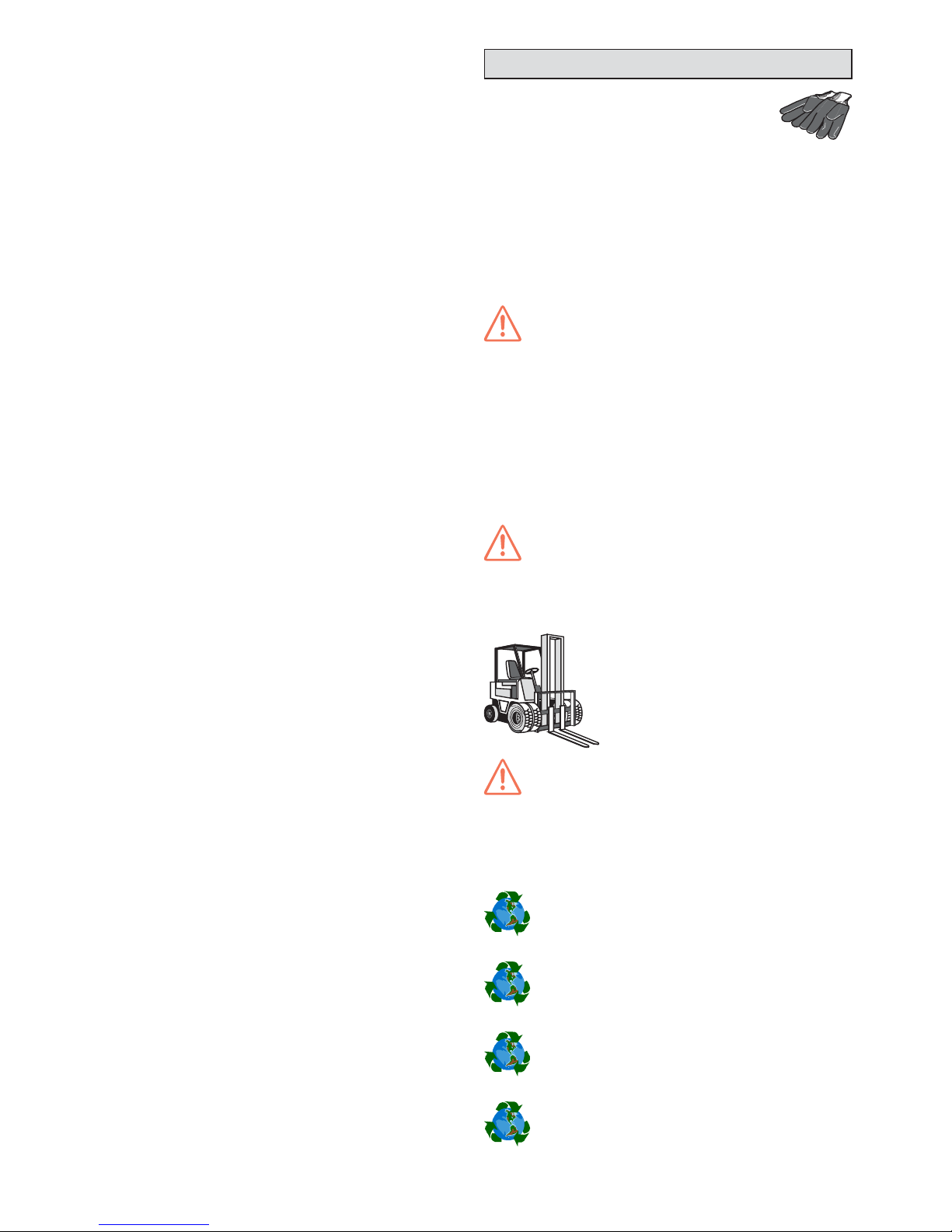
Lift the appliance with a fork-lift truck inserting the forks under the pallet, and carry it to
the place of installation, making sure the
load is balanced.
CAUTION:
Do not push or pull the appliance to move it, as it may tip over.
B.1.2.2 Packing disposal
Packing materials must be disposed of in compliance with current
laws in the country where the appliance is used.
Recyclable plastic parts are marked as follows:
polyethylene: outer wrapping, instruction booklet bag
PE
polypropylene: straps
PP
polystyrene foam: corner protectors
PS
pressboard: corner protectors
B.1 INSTALLATION
Page 3
21
The symbol L shown on the product means that it must not be
considered as domestic refuse, but rather must be disposed of
properly, in order to prevent any negative consequence for
individuals or the environment.
For further information concerning the recycling of this product,
contact the product’s local retailer agent, after sales technical
service or the local authority for waste disposal.
B.1.3 POSITIONING
B.1.3.1 General instructions
Install the equipment, taking all the safety precautions required for this type of operation, also respecting the relative
fire-prevention instructions.
Place the appliance in a well-ventilated place, away from heat
sources such as radiators or air-conditioning systems, in order to
allow correct cooling of the refrigerating unit components. Insufficient ventilation will in fact damage the appliance and prevent it
from working properly. Also, if the temperature is very high, the
compressor will activate more frequently and for longer periods
of time, resulting in higher consumption of electrical energy.
Keep the ventilation openings free of any sort of obstruction.
Never cover the condenser, even temporarily, as this may compromise its proper operation and therefore that of the appliance.
If the appliance is installed in rooms where there are corrosive
substances (chlorine, etc.), it is advisable to go over all the
stainless steel surfaces with a cloth soaked in paraffin oil to create
a protective film.
The equipment’s performance is guaranteed at an ambient
temperature of +38°C. In any case, the max. ambient temperature at which the equipment can operate is +38°C.
Adjust height and levelling by means of the levelling feet,
while at the same time checking the doors for proper closure.
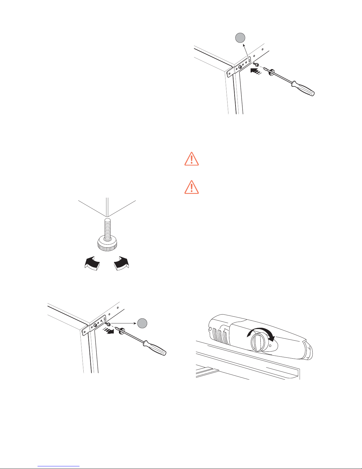
Align the door with the side, adjusting the hinge on the bottom of
the appliance: remove screw "a" from its seat
b
a
and screw it in slot "b" provided on the edge as shown in the figure
b
b
Now, with the hinge loosened, the door can be aligned.
After completing the operation, tighten the screw.
Make sure the floor on which the appliance stands is perfectly
level, in order to ensure its optimal operation.
CAUTION:
the appliance must be level, otherwise its operation could be
compromised.
CAUTION:
wait at least 2 hours before starting the appliance to allow the oil
to flow back into the compressor.
B.1.3.2 Instructions for "V170" undercounters
For positioning "V170" undercounters under a worktop, proceed
as follows:
• undo the screws fixing the top to the appliance, located at the
back;
• slide the top outwards a little to release it from the stops and
remove it from its seat;
• undo the screws fixing the rear feet to the appliance;
• remove the 3 mm spacer from the feet and reposition them in
their seats;
• lastly, fit the front feet and adjust them until the appliance is at
the required height.
- ADJUSTMENT OF TEMPERATURE IN REFRIGERATED
APPLIANCES:
Turn the knob of the thermostat to “6”, “1” or any position in
between.
0
6
The thermostat knob is located at the upper right and is used to
set the temperature at which you wish the appliance to work. The
most suitable operating temperature needs to be selected in light
of the following factors:
• the ambient temperature in which the appliance operates;
• how often the door is opened;
• the amount of food stored;
• the position of the appliance with respect to the setting where
it is installed.
Page 4

22
"V160" freestanding counters and "V170" undercounters are
normally provided with the door hinges on the right-hand side. To
change to hinges on the left-hand side, proceed as follows:
• disassemble the lower hinge;
• disassemble the door;
• remove the door;
• unscrew the pin of the upper hinge and re-install it on the
opposite side of the cabinet;
• unscrew the foot and re-install it on the other side of the cabinet;
• re-install the door and the hinge on the opposite side of the
cabinet;
• unscrew the handle and re-install it on the opposite side after
having perforate the plugs with an auger.
NOTE:
when the door has been reversed, make sure that the magnetic seal adheres perfectly to the appliance. If the ambient
temperature is low, the seal may not adhere perfectly to the
cabinet. If this happens, wait for the seal to return to normal
on its own, or you can speed up this process by heating the
involved part with a hair dryer.
D.1.1INSTRUMENT (refer to figure 2)
A - Digital thermostat display
D.1.2 DIGITAL THERMOSTAT DISPLAY
The digital thermostat has a 3-digit electronic display for showing
the temperature measured by the sensor, and three LEDs (refer
to paragraph D.1.5).
D.1.3 KEYS
The digital thermostat comprises 4 keys for control and programming the instrument.
- Multifunction “UP” key
for increasing the values and
activating manual defrost.
- "DOWN" key for decreasing the values.
- “fnc” key
fnc
with ESC (quit) function.
- “SET” key
set
for accessing the Set point.
When switched on, the instrument carries out a Lamp Test, i.e. for
a few seconds the display and LEDs flash, verifying that it is
working properly.
D.1.4SWITCHING ON AND TEMPERATURE ADJUSTMENT
To start the appliance, you need only to plug it in.
To SET the compartment temperature, follow these steps:
- Press and release key
set
the message “SEt” appears.
- Press the key
set
again and the SET POINT value appears
on the display.
- Change the SET value by pressing the increase value "UP" key
or the decrease value “DOWN” key .
If no button is pressed for 15 seconds (“TIME OUT”) or by
pressing the “fnc” key once, the digital thermostat memorizes the
last set value and the normal display is restored.
The temperature is automatically controlled, but it can be increased or decreased as follows:
• Position “1” = internal temperature warmer
• Position “6” = internal temperature colder
• Position “0” = cooling deactivated / OFF
For especially harsh operating environments, with ambient tem-
peratures higher than 32°C and high humidity, it is advisable to
set the thermostat between 1 and 4.
In general, it is advisable to set the knob to the intermediate
position.
- ADJUSTMENT OF TEMPERATURE IN FREEZERS:
Refer to paragraph D.1.
B.1.5 ELECTRICAL CONNECTION
Before undertaking any procedure involving electrical connec-
tion, we recommend cleaning the cell with lukewarm water and
neutral soap, or with products that are 90% bio-degradable (to
reduce the emission of pollutants into the environment ), then
rinse and dry carefully.
Plug in the appliance.
N.B.: The plug must be accessible even after positioning the
appliance in the place of installation. Also make sure the plug
is not crushed by the appliance. If the power cord is damaged it may overheat and catch fire or cause a short circuit.
When making the electrical connection, make sure to respect that
given on the data plate.
The appliance works on a single-phase 230V 50Hz power supply
Connection to the electrical power supply must be done in
accordance with current regulations.
To connect to the power supply, insert the power plug in the
corresponding power socket, firstly making sure that:
- The plug has an efficient earth connection and the mains
voltage and frequency correspond to that given on the data
plate. In case of any doubts regarding the efficiency of the earth
connection have the circuit checked by a qualified technician.
- In order to protect the appliance from possible dispersion,
overloads or short-circuits, a suitable differential thermal
magnetic circuit-breaker realized in compliance with current
standards. For proper sizing of the switch, refer to the absorbed
power as indicted on the technical data plate of the appliance.
- After making the connection, with the appliance operating
check that the rated voltage level does not fluctuate by ± 10%.
Note: If the power cable is damaged it must be replaced by
the technical assistance service or in any case by qualified
personnel, in order prevent any risk.
The connection must be made with cable of suitable section.
Insert and secure the cables with the special cable clamp.
Correctly connect each wire to the corresponding terminal.
The manufacturer declines any liability for damage or injury
resulting from breach of the above rules or the current
electrical safety standards in the country where the appliance is used.
C.1 DOOR REVERSIBILITY
D.1 USE OF DIGITAL THERMOSTAT ON
"V160" FREESTANDING FREEZER
COUNTERS
Page 5

23
The temperature range is set from a minimum to a maximum,
according to the following values:
Position Minimum = -15°C
Position Maximum = -22°C
D.1.5 DIGITAL THERMOSTAT INDICATOR LED
The digital thermostat has 3 LEDs indicating:
- LED
on indicates activation of the compressor, LED
flashing indicates compressor delay.
- LED
on indicates manual defrost in progress; when
flashing it indicates manual activation.
- LED
on indicates an alarm has triggered during
appliance operation.
D.1.6 ALARMS AND SIGNALLING
D.1.6.1 Alarms and signalling
The alarm is signalled by an LED
coming on at the alarm
icon.
The alarm signal due to a faulty cell sensor (referred to sensor 1)
appears directly on the instrument’s display with the indication
“E1”.
The alarm signal due to a faulty evaporator sensor (sensor 2)
appears directly on the instrument’s display with the indication
“E2”.
The maximum and minimum temperature alarms, referred to the
thermostat sensor, are defined by the parameters “HAL” (maximum temperature alarm) and “LAL” (minimum temperature alarm).
The latter are not shown on the display, but they can be viewed
by entering the folder “AL”.
Faulty cell sensor alarm
DISPLAY ALARM
High cell temperature sensor alarm
E1
Low cell temperature sensor alarm
AH1
AL1
E2 Faulty evaporator sensor alarm
D.1.7 DEFROSTING
- Automatic defrost
The appliance is equipped with an automatic defrost function.
This function is signalled by lighting up of the DEFROST LED
.
The defrost water is run into a bowl and automatically evaporated.
- Manual activation of defrost
Keep the “UP” button pressed for at least 5 seconds to
start a manual defrost cycle. This function is signalled by lighting
up of the DEFROST LED .
If defrost conditions do not exist, the display flashes three times
to signal that the operation will not be carried out.
Defrosting cannot be started during the programming phase.
CAUTION:
Do not use spray defrost products on the freezers. They can be
harmful to the health and/or they may damage the materials of
which the appliance is made.
Note: defrosting takes place automatically also in refrigerated appliances. Defrost water is collected in a container in
the rear section, and from there it evaporates. Clean the drain
hole with the pipe-cleaner provided for this purpose. This
pipe-cleaner must be removed if the cavity is clogged (see
following figure).
D.1.8 PRODUCT LOADING (for all models)
Distribute the product evenly inside the compartment (away from
the door and back) in order to ensure good air circulation. The
racks can be placed in various positions thanks to the guides on
the walls of the cell.
Cover or wrap food before placing it in the refrigerator and avoid
putting very hot foods or steaming liquids inside. Do not leave the
door open any longer than necessary when placing food in the
refrigerator.
We suggest keeping the keys in a place which is accessible only
by authorized personnel. To prevent use of the appliance by
unauthorized personnel, it is advisable to lock it at all times.
For the maximum loads for each shelf, adhere to the following
table:
SHELF MAX. LOAD
"V 160“ FREESTANDING
COUNTER
"V170“ UNDERCOUNTER
10 kg
10 kg
SUGGESTIONS FOR REFRIGERATED MODELS:
• Meat (all types): should be placed in plastic bags and
preferably set on the lowest shelf. In this position it can be
conserved for a maximum of one or two days.
Page 6

24
• Cooked foods, cold plates, etc.: these must be well-covered
and can be set on any shelf.
• Butter and cheese: these should be wrapped in plastic
wrapper or aluminium to prevent contact with the air and they
can be set on any shelf.
• Bananas, potatoes, onions and garlic, if not packaged,
should not be stored in the refrigerator.
NOTES FOR FREEZER MODELS:
never insert carbonated beverages as they may explode.
Frozen products placed on top of the unit may cause con-
densation to form due to the cold. This compartment contains the electronic components. Should water reach these
components, the appliance may be damaged by a short
circuit. Therefore, do not place frozen foods on top of the
appliance.
To defrost frozen foods, place them in the refrigerator, so
that the cold from the frozen foods is used to cool the
refrigerator itself.
D.2.1 PRECAUTIONS FOR MAINTENANCE
Routine maintenance tasks can be performed by non-specialized
personnel provided the instructions given below are carefully
followed. The manufacturer shall not be held responsible for
any operations carried out on the machine if these instructions are not complied with.
ATTENTION:
Do not touch the equipment with wet hands or feet or when
barefoot. Before carrying out any cleaning or maintenance,
disconnect the appliance from the electrical mains and
carefully pull the plug to disconnect the machine. Do not
remove the safety devices for carrying out routine maintenance. Use suitable protection equipment (protective gloves).
D.2.2 CLEANING THE CABINET AND ACCESSORIES
Clean stainless steel parts every day using lukewarm water and neutral soap or products that are
over 90% biodegradable (in order to reduce the
emission of pollutants into the environment), then
rinse and dry thoroughly. Do not use
solvent-based detergents (e.g. trichloro-ethylene) or abrasive powders for cleaning. Do
not use spray defrost products on the freezers.
They can be harmful to the health and/or they may
damage the materials of which the appliance is
made. It is advisable to go over the stainless steel
surfaces with a cloth moistened with paraffin oil in
order to create a protective film.
Frequently check the power cable and replace it if
it shows signs of wear.
Have the equipment periodically checked (at least once a year).
D.2.3 CELL CLEANING
To clean the cell properly, all of the racks must be removed. They
must therefore be removed from the cell before you start cleaning. To extract them, just pull them towards you (you can put them
back in afterwards by proceeding in the reverse manner). Clean
the cells with products that are more than 90% bio-degradable,
then rinse and dry thoroughly.
D.2.4 PERIODICAL CLEANING OF THE CONDENSER
WATCH OUT FOR THE ELECTRICAL CABLES!
The condenser can be cleaned with a brush, provided the bristles
are not in steel or a material that can compromise good operation,
or with a simple paintbrush to get rid of dust.
D.2 ORDINARY MAINTENANCE
Special maintenance must be carried out by specialized
personnel, who may request the service manual from the
manufacturer.
BEFORE CARRYING OUT ANY SPECIAL MAINTENANCE, MAKE SURE YOU ARE WEARING
PROTECTIVE GLOVES AND A MASK.
ATTENTION:
Do not touch the equipment with wet hands or feet or when
barefoot. Unplug the appliance before carrying out any
cleaning or maintenance. Pull the plug out carefully to disconnect the machine. Do not remove the safety guards. Use
suitable protection equipment (protective gloves).
D.3.1 REPLACING THE POWER CABLE
To replace the power cable, proceed as follows:
• disconnect the power supply;
• open the compressor box on the back of the appliance;
• replace the power cable;
• close the compressor box again;
• switch the power on.
CAUTION:
Do not clean the appliance with jets of water.
D.3.2 PRECAUTIONS IN CASE OF PROLONGED DISUSE
If the appliance is not going to be used for a long period, take the
following precautions:
• disconnect the plug from the power socket;
• remove all food from the compartment and clean the inside and
the accessories;
• leave the door ajar so that air can circulate inside, preventing
the formation of unpleasant odours.
• Air the room regularly.
D.3.3 LAMP REPLACEMENT (only for "V160" freestanding
refrigerated counters and "V170" undercounters)
To replace the internal lamp, proceed as follows:
• disconnect the power supply;
• unscrew the fastening screw from the light fixture;
• disconnect the removable part by pressing on it as shown in
the figure
• replace the lamp with one of the same power;
• put the removable part back in place;
• screw the fastening screw of the light fixture back in;
• switch the power on.
D.3 SPECIAL MAINTENANCE
Page 7

25
D.3.4 REPLACING COMPRESSOR COMPONENTS
Whenever any of the compressor components has to be replaced, the electrical box protection must be removed as follows:
b
1
b
3
b
2
Using a flat blade screwdriver, press on the plastic retainer inside
the box (phases 1 and 2). Now the box is released and can be
removed from its seat (phase 3).
D.4.1 WASTE STORAGE
At the end of the product’s life-cycle, make sure it is not dispersed
in the environment. The door must be disposed of before disposing of the rest of the appliance.
Special waste materials can be stored temporarily awaiting
disposal by means of treatment and/or permanent storage. The
current environmental protection laws in the user’s country must
be observed.
D.4.2 PROCEDURE FOR PRELIMINARY DISMANTLING OF
THE APPLIANCE
Different regulations are in force in the various countries, therefore the provisions laid down by the laws and the competent
authorities in the countries where disposal takes place must be
observed.
In general terms, the refrigerator must be taken to a specialized
collection/demolition centre. Dismantle the components and group
them together according to their chemical characteristics, remembering that the compressor contains lubricant oil and coolant,
which can be recycled, and that the refrigerator components are
classed as special waste which can be disposed of with urban
waste.
Make the appliance unusable by removing the power cable and
any compartment locking mechanisms, in order to avoid the risk
of someone becoming closed inside.
DISMANTLING OPERATIONS MUST BE CARRIED OUT BY
QUALIFIED PERSONNEL.
• Quality control testing receipt
• Wiring diagram
• Installation diagram
D.5 ENCLOSED DOCUMENTATION
D.4 WASTE DISPOSAL AND
DE-COMMISSIONING
Page 8

26
D.6.1 QUICK TROUBLESHOOTING GUIDE
In some cases, faults can be remedied easily and quickly; the following is a list of some faults and relative remedies:
THE INSIDE TEMPERATURE IS
TOO HIGH:
THE APPLIANCE IS
EXCESSIVELY NOISY
1. Make sure the applianc e is level. Of f balance positioning
may c ause v ibr ation.
or part s which may star t r esonat ing.
2. Make sure the applianc e is not t ouc hing other appliances
2. Make sure there is no heat source near t he applia nce.
3. Make sure the door c loses properly.
1. Make sure the plug is properly inserted in t he power socket .
2. Chec k t hat the socket is powered.
1. Chec k t he thermostat setting;
THE APPLIANCE DOES NOT
SWITCH ON:
If the fault persists after having carried out the above checks, contact Technical Assistance, remembering to give the following details:
• the nature of the fault;
• the appliance PNC (production code);
• the Ser. No. (appliance serial number).
N.B.: the code and serial number are essential for identifying the type of appliance and date of manufacture.
E.g: PNC 726479 00 - Ser.No. 54000010
726479:refrigerated table
54000010: manufactured in 2005, week 40, 10th piece.
D.6 TROUBLESHOOTING
PNC 726479
Ser.No. 54000010
 Loading...